
Abstract
Inertial navigation systems based on microelectromechanical systems (MEMS) sensors offer advantages that include small size, light weight, low power consumption, strong environmental adaptability, and low cost. These advantages make these sensors particularly suitable for application to precision-guided munitions, which commonly have poor launching environments, strict volume and power consumption requirements, and high cost sensitivity. In this article, the key technologies required for missile-borne integrated navigation systems and the solutions for the problems with each of these technologies are analyzed. An attitude angle estimation method for satellite-assisted MEMS measurement information is proposed that solves the in-flight alignment problem. A high-precision combination of satellite positioning and microinertial navigation is realized through design of a new integrated algorithm framework. The experimental results show that the proposed methods can effectively solve the current problems in guided ammunition navigation.
Introduction
Modern warfare requires weapons and military equipment to have characteristics that include a high degree of informatization, high guidance precision, and a high combat efficiency-to-cost ratio. Informatization and guidance have become the main trends in the development of traditional ammunition for the new era. When a weapon’s hit precision is increased by one time, it is almost equivalent to increasing the amount of ammunition by 8 times, which thus reduces the cost of ammunition consumption and the logistic support burden. The development of guided ammunition requires increased levels of precision and reliability for missile-borne navigation systems. These navigation systems are required to provide comprehensive and accurate navigation and positioning information, to support all-weather operations, to have strong autonomy, and to provide good antijamming performance. Microinertial sensors offer the advantages of small size, light weight, high-impact resistance, low power consumption, and low cost. When combined with satellite positioning systems, microinertial sensors not only have the advantages of the full autonomy of the inertial navigation system, but also have the high-precision positioning characteristics provided by the satellite system with zero accumulation of position errors; this combination can compensate for the shortcomings of the inertial navigation system and the single positioning mode of the satellite system, provide higher navigation accuracy and enhance the antiinterference capabilities of guided munitions.1,2 However, while the development of microinertial navigation devices has progressed very rapidly and can meet the application requirements of guided munitions, the cost of these microinertial devices increases with increasing performance, the consumption of guided munitions is high, and the device cost is sensitive. If this cost can be reduced through algorithm optimization, it may provide a good system solution.3,4
A microelectromechanical systems (MEMS) sensor is a device and a system with characteristic dimensions ranging toward the micron level that is manufactured using microelectromechanical processing technology and has the capacity to convert sensations into electrical signals. Information technology is an important and powerful resource for the development of human society in the 21st century. Sensor technology, as an information acquisition technology, has become one of the three main pillars of modern information technology. MEMS sensor technology represents an important development direction for modern sensor technology. In the late 1980s, the rapid development of MEMS technology greatly accelerated the development of both microsensor and microactuator technologies.
Microsensors based on MEMS technology are characterized by their small size, light weight, low cost, low power consumption, high reliability, easy mass production, ease of integration, and multiple functionalization capabilities. The MEMS microsensor is thus an indispensable technology for the development of a variety of automated devices and modern weapons equipment. These sensors have a wide range of potential applications and are regarded as highly important technology throughout the developed world.
Current MEMS-integrated navigation systems for guided munitions applications are represented by the HG19xx and IGSxx series that were developed jointly by Honeywell and Draper Laboratory. The design goal was to design, develop, and produce a sensor that is able to withstand an overload of more than 20,000 g, has launch accuracy of better than 0.5°/h and a volume of less than 12.9 cm3, and has an antiinterference capability. This goal can be achieved and can be enhanced by the combination of the MEMS system with global positioning system (GPS) technology.
After three development stages, the HG1920, HG1930, and HG1940 inertial measurement units and the IGS200, IGS202, IGS204, and IGS250 integrated navigation system product series have been gradually produced; examples are shown in Figure 1. However, these devices all cost more than US$1000 each.

Honeywell microelectromechanical systems sensor products.
The relationship between cost and performance is illustrated in Figure 2.
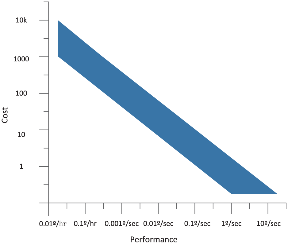
Relationship between cost and performance.
MEMS sensors have brought considerable change to military applications of navigation technology because of their good reliability and relatively low cost, but they still need to be improved in terms of the following aspects:
The market potential in this field has not yet been fully realized.
Further investment is needed to continue the research.
Performance needs to be improved further, and combined with smaller device size and lower cost.
Gyroscope chips, such as the ITG-3200 three-axis gyroscope chip produced by InvenSense, have a range of approximately 2000°/s, can resist impacts of 10,000 g, have a temperature compensation function, and have interintegrated circuit (IIC) digital output interfaces.
Acceleration sensing chips, such as the ADO ADXL345 three-axis accelerometer chip, have a large configurable range of 16 g, can operate properly in temperatures ranging from 40 °C to 85 °C, can resist impacts of 10,000 g, and can be used with serial peripheral interface (SPI)/IIC configurations for their digital output interfaces. Low-cost triaxial gyroscope and accelerometer chips are shown in Figure 3.

Low-cost triaxial gyroscope and accelerometer chips.
Literatures5–9 introduce the integrated navigation algorithm under the condition of large misalignment angle. However, when the accuracy of the MEMS sensors are relatively poor, the convergence speed of the algorithm is very slow. The convergence curves for the ammunition’s attitude are shown in Figure 4.

Three attitude misalignment angle convergence curves for the ammunition.
From the simulated curves, it can be seen that while the pitch, roll, and heading misalignment angles do have a convergence trend, the convergence speed is low.
This result is obviously not practical. Therefore, in the case of a common projectile, which has an approximately parabolic maneuvering mode, the effectiveness of the estimation of the roll and the other attitude angles is poor.
At this stage, an idea is proposed that introduction of the attitude angle calculation model will allow the attitude angle to be calculated directly from the measured data from the satellite and the MEMS sensors. The three misalignment angles can also be regarded as observation variables, and the gyroscope drift can be calculated based on the divergence velocities of the three misalignment angle curves, thus improving the degree of observability of the gyroscope bias.
The purpose of this study is to improve the algorithm that makes it possible to develop ballistic MEMS-integrated navigation systems using similarly low-cost sensor devices.
Key technology analysis and solutions
As a result of the small diameters, poor launch environments and strong roll-based maneuverability of guided munitions, higher requirements and new challenges are proposed for the development of inertial systems for guided ammunition applications.
Given the characteristics described above, the design of the inertial system for guided ammunition should be focused on the design of an anti-high-overload structure, in-flight initial self-alignment of attitude, integrated MEMS/global navigation satellite system (GNSS) navigation, and error calibration and compensation technology for the micro-inertial devices when operating under highly dynamic conditions. Anti-high-overload technology is realized through shock absorption design, encapsulation, and other technical means, which are not described in detail in this work. This article focuses on the description of the navigation algorithm for use in highly dynamic environments.
Large misalignment angle model for integrated navigation
At present, the precision of low-cost MEMS inertial devices is very poor. In general, the precision of a typical silicon micro-gyroscope ranges from tens to hundreds of degrees per hour. Therefore, the in-flight alignment conducted by the miniature inertial measurement unit (MIMU) using GPS information is usually performed under large misalignment angle conditions.
Rapid and accurate in-flight alignment at this large misalignment angle will greatly improve the reaction speed and the operational accuracy of guided munitions, which is of major significance for modern applications. Most previous alignment methods are based on a linear error equation under the assumption that the error angle is small, and the error angle is then estimated using a Kalman filter. When the error angle is large, the traditional linear small error equation cannot be used to describe the system characteristics, which means that a nonlinear error propagation equation and a nonlinear filtering algorithm are required.
The quaternion error equation that was proposed in Yu et al. 7 is applicable in the case where the three attitude error angles can all have any value.
In Wei and Zhang’s literature, 10 the quaternion error equation and extended Kalman filter (EKF) technology have been used to provide effective improvements in the alignment accuracy of a strapdown inertial navigation system with a high-precision inertial device at a large misalignment angle. Lu et al. 11 proposes an attitude estimation algorithm when large external acceleration occurs, which can effectively improve the performance of the algorithm.
Attitude quaternion error equation
Here, an additive quaternion is used to establish a quaternion error equation.
Define,

Quaternion transformation matrix

The specific expression is

Velocity error equation
Define

Here, we introduce


By ignoring the influence of

Among these terms,
Position error equation

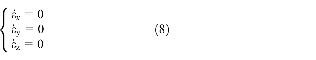
Inertial device error equation
The system only works for a short time of a few minutes, so the zero bias drift is very low and can be neglected.
In this article, the gyroscope drift is modeled as a combination of a random constant and white noise. The gyroscope’s constant zero bias is taken to be the system state, and the equation for the gyroscope’s zero bias error is as follows
The accelerometer drift is also modeled as a combination of the random constant and white noise. The accelerometer at a constant zero bias taken to be the system state, and the accelerometer’s zero bias error equation is given as follows

By combining the error equations for the quaternion, the velocity, the position, and the inertial device that were derived above, the system state equation can be obtained as follows
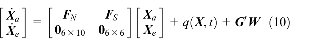
Here,

The system noise vector is composed of the gyro zero bias and the accelerometer zero bias, which is given as

The difference between the position and the velocity calculated using the strapdown inertial navigation system and the position and velocity measured using GPS is taken to be the measurement quantity. The measurement equation is thus given as follows

Note that the observation vector is

in which
Three attitude angles estimated by attitude angle filtering algorithm are converted to attitude quaternion
The measured noise vector

Unscented Kalman filtering technology
The EKF is widely used in nonlinear filtering applications because it offers advantages such as a simple method and easy implementation. However, an EKF filter linearizes the nonlinear function, that is, it ignores the influence of the Taylor expansion of the nonlinear function on the higher-order terms; therefore, when the system is highly nonlinear, the EKF estimation accuracy drops dramatically and can even diverge.
At present, a particle filter (PF) estimation method based on an approximate probability density distribution is quite popular for nonlinear filtering because it is not necessary to understand the specific expansion formula of the nonlinear function in detail.12–14 The probability density distribution can be solved directly by solving the nonlinear function of the particles. The unscented Kalman filter (UKF) can be regarded as a type of PF. The UKF uses a deterministic sampling strategy to approximate nonlinear distributions. When compared with general PF filtering, the UKF contains fewer particles, which has the major advantage of requiring small amounts of computation and is thus more practical.
The UKF algorithm is a Kalman filter algorithm based on the unscented transform (UT).15,16 The UT transform method is used to obtain the mean value for a one-step prediction and the mean square error for one-step prediction of states. The steps of the UKF algorithm are given as follows:
Initialization


Computational sampling (sigma) point:
The 2n + 1 sigma points of the state are selected (where n is the dimension of the state)

In the case where the system state variables
When
Time update:
The posterior mean and the variance of the state are then calculated using UT technology


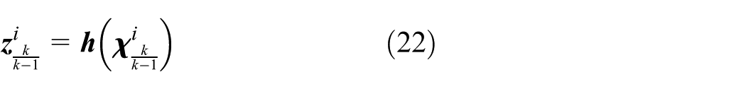

Measurement update:
The measurements are updated using standard Kalman filtering, but the formulas used for this purpose are different


The UKF algorithm does not approximate the nonlinear function itself, but instead approximates the probability density distribution of the nonlinear function. Therefore, the algorithm is effective, regardless of the complexity of the system state equation, and its accuracy is much higher, and may reach the level of the three-level Taylor expansion. In terms of computational complexity, the real-time performance of the UKF algorithm is relatively poor, while its computational complexity is approximately 3 times that of the EKF, and a large part of the computational resources required for the UKF are focused on decomposition of the covariance matrix. If the decomposition method used for the
Observability analysis
Under the moving base condition, the piecewise constant system (PWCS) method is used to analyze the observability of the model. 17 The discrete linear time-varying system is set up as follows

In the above formula,
The observability of the system state equation is independent of the input, and the observability matrix of the system in the

A singular value decomposition is performed for the striped observability matrix (SOM) of the PWCS.

Here,

Here,
Assuming that the appearance measurement of the system is

Equation (33) is then substituted into equation (31), and the following is obtained

Here,
From the given appearance measurement

Among these parameters,
The expression for the degree of observability 18 is given as shown below

In the formula above,
An observability analysis of the large misalignment error model is also carried out.
The additive quaternion is used to describe the attitude angle, so the three attitude angle errors are also reflected in the additive quaternion error. Here, the quaternion errors are expressed as
Attitude angle estimation method
Following satellite positioning, the pitch angle and the heading angle of the projectile axis can be calculated approximately using the measured values of the projectile velocity provided by the satellite positioning device (while ignoring the effects of the nutation and movement of the projectile)

In the formula,
By differentiating the heading angle and the pitch angle of the projectile axis, the lateral and pitch angular velocities of the projectile can be calculated. Then, using the geometric relationship of the gyroscope installation within the inertial navigation system, the angular velocity measured using two gyroscopes oriented perpendicular to the projectile axis can be deduced, and the mathematical relationship among the lateral and pitch angular velocities and the roll angle of the projectile can be calculated.
According to external ballistics theory, the outputs of the Y axis and Z axis angular velocities in a fixed coordinate system are given as follows 19
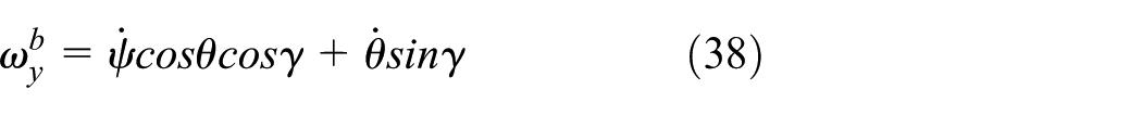

Let

The sine and cosine functions of the roll angle of the projectile can also be expressed as

where
The state variables for Kalman filtering are established as follows

Of these variables,
Therefore, the Kalman filtering measurement equation is established as shown below

The state equation of the Kalman filtering system is then established as follows

The filter state variables, the filter measurement equation and the state equation are then inserted into the Kalman filter iteration equation to estimate the sine and cosine functions of the projectile roll angle. The projectile roll angle can be obtained by calculating the arc tangent of the function value and judging the quadrant with the positive and negative signs of the roll angle sine and cosine function values

Experimental verification
At first, numerical simulation is carried out by MATLAB.
A simplified block diagram of the algorithm is shown in Figure 5.
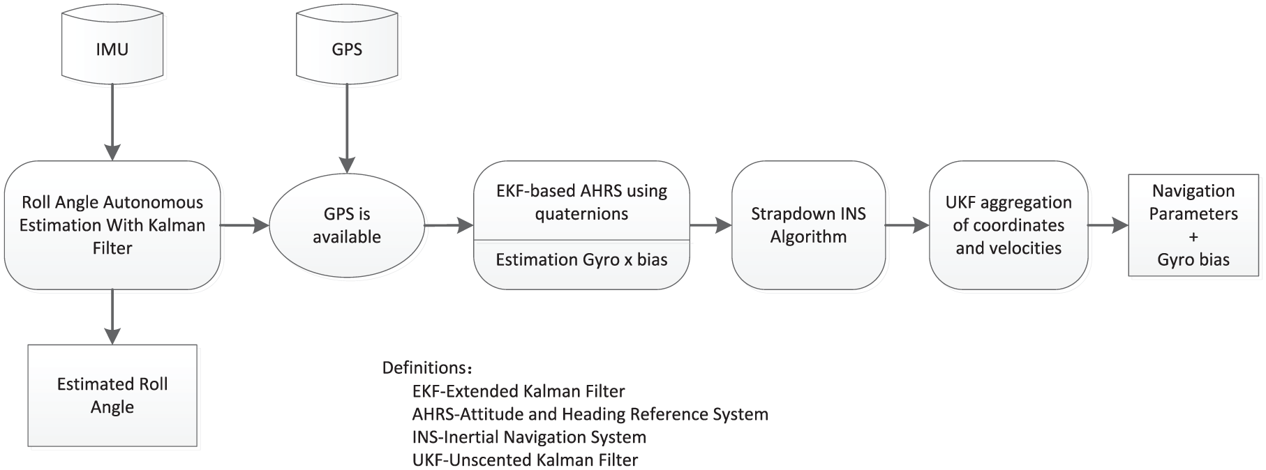
Simplified block diagram of the algorithm.
The observability is related to the maneuverability. In some maneuvering cases, certain states are unobservable, but most states in the complete process can be observed; however, the magnitudes of these observabilities are different. First, the position and the velocity in the three directions are external measurements, so the observability degree is approximately 1. For the attitude, the data for a projectile without a gliding wing have the lowest quaternion error observability at approximately 0.5. The data for a projectile with a gliding wing have the relatively high degree of observability of roughly 1.1 to 1.2. The degree of observability of the quaternion for uniform speed and flat flight is slightly higher than that for the corresponding condition with the gliding wing at approximately 1.2 to 1.6. The degrees of observability of the accelerometer zero bias and the gyroscope zero bias are small and are of the order of 0.01 in magnitude. When the measurement noise is high and the system model is uncertain, the observable accelerometer zero bias and gyroscope zero bias information can easily be submerged in the noise, thus making the estimation process more difficult.
The projectile’s flight time in the air is 100 s, the initial launch pitch angle is 56°, the initial projectile velocity is 720 m/s, and its rotational speed is 5 r/s. GPS position accuracy: 2.5 m CEP (horizontal accuracy) and 5.0 m CEP (vertical accuracy); GPS velocity accuracy: 0.25 m/s CEP (horizontal accuracy) and 0.5 m/s CEP (vertical accuracy). The improved algorithm is simulated by MATLAB. Simultaneously, the rank of the SOM is calculated and extracted online. The observability of the 16 states of the system is simulated and saved, and a curve of the change in observability is drawn as shown in Figure 6. Figure 7 shows the height and pitch angle contrast curve between GPS and integrated navigation system. Figure 8 shows the attitude estimation error curves of the two algorithms.

Observability curves for attitude quaternion. (a) Observability degree curve of
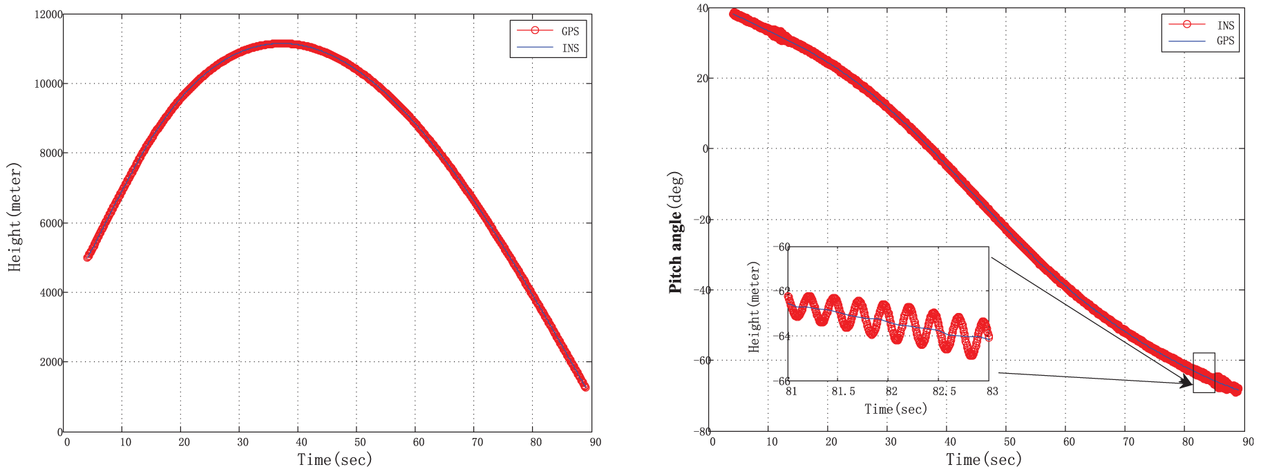
The height and pitch angle contrast curve between global positioning system and integrated navigation system.

The attitude estimation error curves of the two algorithms.
And then, to verify the effectiveness of the algorithm, a projectile with an integrated navigation system based on low-precision MEMS sensors and a calibrated geomagnetic attitude angle measurement device was used for comparison.
The projectile was fired at a pitch angle of 60° with a muzzle velocity of 710 m/s and an initial roll angle velocity of approximately 25 r/s. Here, the gyro zero bias in the three directions was about 1°/s, the random drift was 0.5°/s, the accelerometer zero bias in the three directions was 500
In the program, the initial roll angle is set at 0°. Figure 9 shows the roll attitude angle error curve, and Figure 10 shows the zero bias identification curve. The position error and velocity error statistics are listed in Table 1.

Error between roll angle output by the integrated navigation system and roll angle from the geomagnetic survey.

X-axis gyroscope zero bias estimation curve.
Error statistics for position and velocity.

The experimental results show that the roll angle achieves alignment less than 3 s after satellite positioning and then maintains high alignment accuracy. The zero bias estimation of the x-axis gyroscope tends to become stable in approximately 45 s. The mean position error is less than 3 m, and the mean velocity error is less than 0.3 m/s. All indicators demonstrate the correctness and effectiveness of the proposed algorithm.
Concluding remarks
In this article, the feasibility of applying an integrated navigation system that was designed using low-precision MEMS sensors to guided munitions is analyzed. The attitude angle estimation method for the satellite-assisted MEMS measurement information is proposed and the in-flight alignment problem is solved. The design of a new integrated filtering algorithm framework allows the high-precision combination of satellite positioning and a microinertial navigation system to be realized, and the initial alignment time is reduced. The experimental results demonstrate that this method can effectively solve the navigation problems of guided munitions using low-cost MEMS sensors.
Footnotes
Handling Editor: Daming Zhou
Declaration of conflicting interests
The author(s) declared no potential conflicts of interest with respect to the research, authorship, and/or publication of this article.
Funding
The author(s) received no financial support for the research, authorship, and/or publication of this article.