
Abstract
Wireless local area network–based broadcasting techniques are a type of mobile Internet Protocol television technology that simultaneously transmits multimedia content to local users. Contrary to the existing wireless local area network–based multimedia transmission systems, which transmit multimedia data to users using unicast packets, a wireless local area network–based broadcasting system is able to transmit multimedia data to many users in a single broadcast packet. Consequently, network resources do not increase with the increase in the number of users. However, IEEE 802.11 does not provide a packet loss recovery algorithm for broadcast packet loss, which is unavoidable. Therefore, the forward error correction technique is required to address the issue of broadcast packet loss. The broadcast packet loss rate of a wireless local area network–based broadcasting system that transmits compressed multimedia data is not proportional to the quality deterioration of the received video signals; therefore, it is difficult to predict the quality of the received video while also considering the effect of broadcast packet loss. In this scenario, allocating equal forward error correction packets to compressed frames is not an effective method for recovering broadcast packet loss. Thus, several studies on unequal loss protection have been conducted. This study proposes an effective, prediction-based unequal loss protection algorithm that can be applied to wireless local area network–based broadcasting systems. The proposed unequal loss protection algorithm adopts a novel approach by adding forward error correction packets to every transmission frame while considering frame loss. This algorithm was used as a new metric to predict video quality deterioration, and an unequal loss protection structure was designed, implemented, and verified. The effectiveness of the quality deterioration model and the validity of the unequal loss protection algorithm were demonstrated through experiments.
Introduction
High-speed network techniques utilized in smartphones, tablet personal computers (PCs), and laptops have quickly expanded in applications to industry and have enabled users to watch multimedia broadcasts anywhere and at any time. This type of broadcasting is called mobile multimedia broadcasting.
The advantage of mobile multimedia broadcasting compared to digital multimedia broadcasting (DMB), digital video broadcasting—handheld (DVB-H), and multimedia broadcast multicast service (MBMS), which require a large-scale system for mobile multimedia broadcasting, is that its wireless local area network (WLAN)-based broadcasting system can easily set up a mobile multimedia broadcasting system.1–6 From now on, the WLAN-based broadcasting system would be expressed as a Wi-Fi broadcasting system.
The WLAN-based broadcasting system is a broadcasting communication technology which is suitable for providing a digital broadcasting service in a narrow area and temporarily. The Wi-Fi broadcasting system uses Wi-Fi data transfer technology to transfer one component of multimedia data to multiple users. The system is composed of a broadcasting server, an access point (AP), and various receiving devices. The broadcasting server performs encoding processes to create and transfer multimedia data.7,8 The encoded multimedia data, which are to be transferred by the AP, should determine the data transmission mode. The Wi-Fi data transferring mode includes both unicast and broadcast methods. The unicast method, which transfers multimedia data through Wi-Fi to users, needs to transfer the multimedia data multiple times to each user. Under circumstances where wireless resources are limited, the unicast data transmission mode might be limited, because its usage of wireless resources increases as the number of users increases. Because broadcast transmission mode enables the transmission of one piece of data to multiple users simultaneously, its service bandwidth does not increase with an increase in users. 9
There are two causes of packet loss during data transmission over Wi-Fi. One is the congestion in the medium access control (MAC) layer, and the other is modulation or coding scheme in the physical (PHY) layer. This article does not reduce the loss itself, but how to improve the received video quality when frame loss occurs.
When losses occur while transmitting multimedia data through Wi-Fi, both modes try to recover packet losses in different ways. In the unicast method, the user who received the unicast packet from the AP transfers the acknowledgment (ACK) packet to the AP, which is when packet losses occur. When the losses occur at the unicast packet after the AP transfer, or at the ACK packet after user transfer, the AP is not able to receive the ACK packet from the user. The AP assumes that losses occur, if it did not receive a response from the unicast packet, and it then retransmits the packet to the users. In unicast transmission mode, this recovery method is called the loss recovery technique by retransmission. It is conducted at the MAC level of the Wi-Fi network.
However, the Wi-Fi AP does not receive the ACK packet from the user in exchange for the broadcast packet. If the user did not receive the broadcast packet transferred by the AP, it is assumed that packet loss occurred. In other words, the broadcast packet is more vulnerable to packet loss than the unicast packet. To address this simplex multimedia data packet loss problem, the forward error correction (FEC) scheme is used in general. The FEC scheme considers the packet losses and adds FEC data packets to the multimedia data packet to be transferred. For example, if there are three original data packets scheduled for transfer, one packet is added to the batch to compensate for packet loss. When those packets are transferred and users can potentially receive more than three packets, the original data packet is recoverable. If the users received less than three packets, they cannot recover the original packet. In order to recover the original data packet while considering the packet loss rate, it is essential that FEC determines the size of the original data set and the FEC data set.
The multimedia data transferred through a Wi-Fi broadcasting system is first encoded and then transferred. This ensures that an effective transmission will occur. The main goal of video encoding is to eliminate time redundancy; therefore, video encoding incorporates standard frames and reference frames. It is impossible to predict the location where packet loss occurs under the Wi-Fi broadcasting system. The packet losses are recovered by the FEC scheme, which is called equal loss protection (ELP). ELP schemes recover packet losses with the same recovery rate toward all video frames. However, considering the principles of encoding and decoding, it is not efficient to equally recover packet losses in terms of received quality of video frames. This is because the quality of video decoding differs based on the location where packet loss occurs, even if it occurs at the same packet loss rate. Therefore, the unequal loss protection (ULP) scheme has been proposed. In a case involving a multimedia encoding video frame, we classify the frame that affects every frame during decoding and the frame that does not affect any frame about packet losses. According to the basic principle of ULP, a high FEC rate is allocated to recover the former frame.
Under circumstances in which network resources are limited and the location of packet loss is unknown, it is not an optimal option to allocate an FEC packet only to recover the important frame considering the average quality of receiving video. In this study, in order to make a difference in the FEC rate to be allocated on each frame depending on the priority of importance, the expected quality of receiving video by frame loss would be used as a parameter. First, it should be possible to predict the quality of receiving video while considering the effect of frame loss. Using the multimedia data, which includes the packet loss rate and the number of packets that comprise the frame, the frame loss rate can be calculated with a binomial. This binomial can be used to predict the quality of the receiving video. This prediction method would vary based on the number of allocated FEC packets.
This study proposes a framework that can adaptively predict the distortion in the quality of receiving video, and it proposes a quality prediction model according to packet losses in order to effectively transfer multimedia video data in a Wi-Fi broadcasting system. The proposed ULP system reflects the scene transition characteristics of the encoded video. According to the principle of video encoding, static video such as news and dynamic video such as sports have different characteristics of the encoded video. Previous studies have proposed a method that uses different weights depending on the frame type, frame size, and frame position of the group of pictures (GOP). However, this article reflects the scene transition characteristics of video. Based on the proposed quality prediction model, a ULP system is designed and implemented. In addition, the validity of the quality prediction model and the effectiveness of the proposed algorithm will be demonstrated.
This study is outlined as follows. In section “Related works,” we describe the related works, such as those focused on packet receiving and sending characteristics in a Wi-Fi broadcasting system, as well as packet recovery techniques. Then, the basic principle of video compression and the structure of video data are described. Next, existing studies on video quality distortion models and ULP are presented. In section “Quality prediction model–based ULP system,” we present an important parameter for system design, video quality criteria, the quality prediction model, and the design of the ULP system based on the quality prediction model. In section “Performance evaluation,” we discuss the implementation of the suggested algorithm for performance evaluation and the environment in which the experiment was conducted. In addition, a description of how to conduct the performance evaluation is provided. This description validates the quality prediction model, the quality prediction model–based ULP system, and the characteristics of Wi-Fi ULP based on the quality prediction model and compares these elements to existing studies. Finally, our conclusions and discussion are presented in section “Conclusion.”
Related works
In a Wi-Fi broadcasting system that does not implement MAC-level retransmissions, packet losses are unavoidable. Moreover, the rate of packet losses increases as the distance between an AP and a receiver increases, and as the data transmission rate over a fixed distance increases. 9
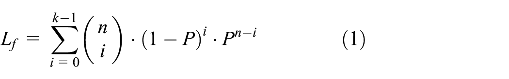
The Wi-Fi broadcasting system uses packet-level FEC schemes to recover lost packets. FEC(n, k) schemes transmit n number of packets, including additional (n – k) number of packets eventually to transmit k number of packets. Frame loss is defined as the single packet loss that occurs when one frame is transmitted to k number of packets. Then, for the n number of packet transmissions, if the users received more than k packets, frame loss would not occur. However, for n number of packet transmissions, if the users received less than k number of packets, frames would be lost. The frame loss probability is calculated with a binomial as shown in equation (1), and Figure 1 presents a frame recovery concept map using packet-level FEC 9

Concept map of broadcast packet loss recovery using the FEC scheme in Wi-Fi broadcasting system.
The video compression technology utilizes H.264 encoding, which eliminates time and space redundancies. H.264 has been developed for use in transferring networks from the beginning of development. In addition, the encoding video is transferred by the GOP unit to reduce the potential for quality deterioration, which is associated with possible transmission losses. One GOP is composed of several frames, which differs based on profile of video. For example, the baseline profile is composed of one I frame and multiple P frames. Each frame type is divided into packets (the unit of Wi-Fi transmission) before being transferred. If one of these packets is lost, the entire frame would be lost as well. Depending on the number of packets that comprise the frame, a different rate of frame loss is calculated using the packet loss rate. Figure 2 shows the video encoding process (the division of frames into packets and their transfer into GOP units).

Data structure map for data transmission of encoded video.
GOP(j) represents the jth GOP. One GOP has M number of frames, which are composed of one I frame and M – 1 P frames. The I frame of the jth GOP is equal to I(j), the P frame of mth of jth GOP is equal to


The video quality distortion modeling research is divided into the one that optimizes the bit rate distortion when encoding the source video and the other that predicts the quality of receiving video when loss occurs after the encoded video is transmitted.
The purpose of rate–distortion optimization (RDO) is to select the macroblock with the minimum distortion rate as the optimal macroblock mode with which to encode the video. This will allow for a minimum bit rate to be achieved without losses, and maximum quality can be attained. One of the factors that facilitated improvements in the H.264 compression rate is the RDO mode. The RDO mode selects the macroblock mode that has the minimum distortion cost by calculating the bit rate and degree of distortion not by the moving cost calculated during the movement prediction process. 10 This mode has the advantage of reducing the beat rate but the disadvantage of increasing coding time.11,12 Recent studies have focused on reducing bit rate, minimizing distortion, and reducing the calculation amount in the RDO area, while studies on discrete cosine transform (DCT) have been trying to overcome these problems by predicting the bit rate and degree of distortion. 13
When transferring the encoded video, after considering the time and space characteristics, transmission losses occur and the quality distortion incurred by these losses is called channel distortion. The research that predicts the channel distortion to packet loss rate has been focused on predicting the amount of channel distortion based on various coding technologies.
Existing studies have predicted the level of video quality using pixels, macroblocks, frames, and GOPs. The loss unit is the transmission unit and the prediction unit predicts the video quality based on the loss unit. The loss unit includes the group of blocks (GOB), frame, macroblock, pixel, and slice; the prediction unit includes pixels, macroblocks, frames, and GOPs.13–16
Zhang et al. proposed recursive optimal per-pixel estimation (ROPE) technology to predict each pixel of decoded video, and the predicted pixels predict the overall frame distortion using mean squared error (MSE). Prediction research based on pixels has expanded the way of modeling mutual relations between two pixels.13,14,17
Ekmekci and Sikora predicted the success and failure of frame losses at the macroblock level. The frame loss that occurs based on the packet loss was calculated using the method that calculates distortion at the macroblock level. 15
He et al. used the characteristics of the intra-refresh rate and DCT coefficient to predict the degree of video quality deterioration at the frame level when it fails to transfer the macroblock or packet through the pixel unit. The frame distortion is based on MSE, and we performed modeling for video quality in cases where the I and P frames were transferred successfully and unsuccessfully. 18
Wang et al. proposed a method that predicts frame loss based on the slice losses inside the frame. His method has similarities with our method in terms of the prediction of frame loss at the unit level. He used a baseline profile and predicted the distortion based on whether I and P frames of a video were lost or not. Then, to determine quality distortion resulting from channel distortion, he generalized that baseline profile by adding the distortion of the current frame to the distortion from transmission loss. 16
While in the existing research distortion is typically calculated by distinguishing between the distortion of the current frame and the distortion amount by the previous frame, and summing up these two amounts to predict the video quality distortion resulted from packet loss. For precise prediction, it is modeled using the technique used for encoding, which generally remains a constant. Those methods that are determined by the encoding technique make it possible to approximately predict the capability of the entire video in one calculation, but difficult to reflect the characteristics of video motion. To solve this problem, we propose a calculation method that adaptively calculates the average video quality in every GOP. 19
The research on how to effectively transmit high-capacity video under circumstances where packet loss and delay occur has been performed in either the application layer or the transmission layer.
In the application layer, the research has focused on multimedia data transmission technologies in a way that decreases the size of transmitted data or minimizes packet loss. The representative technologies include error concealment and recovery technology, 20 multi-layered compression technology, 21 and scalable compression technology,22,23 which minimize the quality deterioration of video for the packet loss.
Error concealment and recovery technologies are classified into one using information between frames and using information inside the frame. The method that uses information between frames uses motion information of the adjacent frame to conceal the error. This method is effective for recovering lost blocks because it could utilize the surrounding information of the lost block, as well as adjacent information close to the time axis. However, this method has a disadvantage in that it is not applicable to video without motion, or video that is compressed with intra-frame. In addition, this method is difficult to apply to video with a fast and complex motion.
The scalable compression technique is a video encoding technique that initiates an applicable service to a different network environment and different kinds of devices with one-bit flow. The scalable video compression algorithm is a next-generation color consistency video compression technique that can be used in television, PCs, and cellular phones with one source. This algorithm enables spatial scalability of display resolution sizes (GCIF, CIF, 4CIF, etc.), temporal scalability of frame rate (7.5, 15, and 30 Hz) and quality scalability (bit rate) to meet user demand.
Along with those scalabilities, the H.264 video compression standard 24 minimizes the data amount and has a higher compression rate than the existing compression standard. However, this higher compression rate requires a high correlation between spatial and temporal scalability between video frames, and it has the disadvantage of being more highly vulnerable to packet losses than the existing compression standard.
One representative packet loss recovery technique used at the transport layer is the automatic retransmission request (ARQ) and FEC. The ARQ is not appropriate for real-time multimedia services because it generates losses due to increased transmission quantity from the retransmission of packet loss. This leads to additional delay and then overloaded packet transmission. Meanwhile, FEC considers losses, adds and transmits additional packets, and therefore receivers can recover the losses. This means that it does not only need retransmission or additional transmission of feedback but also in less delayed time. 25
Under circumstances where network resources are limited, using FEC to recover packet loss at the same recovery rate with the encoded frames is not effective, considering the quality of receiving video. Therefore, ULP is proposed. 26
The existing ULP studies classified the data structure to select priority based on the characteristics of the network and the multimedia streaming into the packet, the macroblock, and the frame and then used the macroblock and the frame to decide the priority of video quality decision.27,28
Cavusoglu et al. 27 use the point that MPEG-2 video has different quality in every picture in order to effectively transmit MPEG-2 video. In the case of MPEG-2 video to packet loss, it has different quality relation weight in every picture, and these different weights are calculated in advance to predict the video quality to packet loss rate. Then, using this prediction, it gives different FEC packets to I, P, and B pictures. This is limited to a certain encoding technique (MPEG-2) and, even if it is applied to MPEG-2 video, the quality of receiving video could be changed depending on the characteristics of the scene changes within the video, which could not be applied to recover packet loss.
Marx and Farah 29 suggest a method for transmitting H.263 video streams on 3G networks. Using the baseline profile, the I and P frames of GOP were classified by the temporal aspect and FEC packet was given. In the GOP, the priority was given as high, normal, and low, and then different FEC packets according to location were given. After rearranging the frames based on the location of the frame within the GOP, packet loss could be recovered and the GOP would be reorganized. Therefore, the method is not appropriate for real-time multimedia, and it also requires another frame classification and combining system.
Chang et al. 28 suggest a technique that is similar to that introduced in Marx and Farah. 29 According to the priority order, the macroblocks of the frame are classified as high, medium, and low, and then those are given different FEC rates to be transmitted. This method ensures real-time features by conducting FEC encoding before channel encoding. However, to minimize quality distortion, it assigns a different FEC rate to the same frame location, which is the same as that in Marx and Farah. 29 Therefore, the transmission system becomes complex and has the disadvantage of accumulating FEC packets in the front of the GOP.
Hartanto and Sirisena present a fixed FEC rate that is proportional to the size of intra- and inter-frames. This technique does not consider quality distortion resulting from loss propagation in the GOP frame, and instead only considers the size of the frame. Therefore, it is not an effective algorithm. 30
Diaz et al. suggest the decision frame set (DFS) as a frame transmission unit and the algorithm that provides a different FEC rate according to frames in order to effectively transmit frames while ensuring the real-time feature of MPEG-2 TS packet. The amount of FEC is decided by the quality distortion model for I frame DFS (I-DFS) and P and B frame DFS (PB-DFS), and the model defines the weight and frame location as a constant depending on the frame type and size; therefore, the mode does not reflect the scene changing characteristics of various videos. 31
Research of Diaz et al. is similar to this study. Diaz et al. constantized the weights according to frame type, frame size, and frame position of GOP. According to the principle of video encoding, static video such as news and dynamic video such as sports have different characteristics of the encoded video. For example, the capacity of I frame and P frame in GOP is different. Diaz et al. proposed not to reflect these characteristics but to use different weights according to frame type, frame size, and frame position of GOP. However, this article reflects the scene transition characteristics of video.
Recently, Jose and Sameer 32 proposed new LUBY transform (LT) codes of application layer forward error correction (AL FEC) for transmission of large-capacity multimedia data in next-generation cellular wireless network and it showed the improvement of video quality using simulation. Haghifam et al. 33 classified the importance of packet into two classes for burst losses occurring in real-time interactive application such as audio and video streaming and allocated additional FEC packets to more important packets. Lv et al. 34 proposed a ULP scheme that gives more FEC packets to field of view (FOV) than non-FOV with less impact on video quality in order to efficiently transmit large-capacity virtual reality (VR) video.
The ULP-related studies have been trying to improve the quality of receiving video about packet loss depending on encoding technology and network environment. The studies focus on topics ranging from factors affecting packet loss in encoding technology to predicting quality of the receiving video. The research on predicting quality of receiving video to packet loss has been generalized using certain techniques during the encoding process. The quality of receiving video about packet loss should consider both encoding technology and the motion characteristics of the subject video. However, ULP-related research has not yet considered video motion characteristics.
Therefore, this study predicts video quality in GOP about packet losses, proposes a Wi-Fi quality prediction model based on a ULP system that calculates receiving prediction quality, and finds the FEC rate of a superior-quality video when different FEC rates were applied.
Quality prediction model–based ULP system
Video quality metric of the proposed system
The peak signal-to-noise ratio (PSNR) is a measure of the quality difference between two frames. The PSNR describes the difference of pixel of the same location of comparing frame using MSE. To calculate PSNR, signal power that represents all kinds of different video is needed. However, the signal power is not available and the maximum value of the 8-bit pixel, which is the square of 255, is replaced to calculate PSNR. Equation (4) describes MSE and equation (5) describes PSNR

where
While PSNR is a quantitative metric of video, mean opinion score (MOS) is a qualitative metric. MOS describes the quality difference between two frames with five stages, which means qualitative video quality differences.
Regarding the video quality deterioration metric for frame loss, PSNR is used in this study to compare the quality of the encoded video to that of the receiving video in which loss has occurred.

At this time, maximum quality occurs when there is no loss and minimum quality occurs when the video is not identifiable due to loss.
In a case where no frame loss occurs, MSE is equal to zero; therefore, PSNR is not defined. However, because
In addition,
In this study, a new video quality metric, Q, is used. It ranges from 0 to 1 and is represented as follows

Q could be calculated with equation (8) and the value of PSNR is measuring value before and after frame transmission

The relation between Q, PSNR, and MOS is described in Table 1. 37
Values of PSNR and MOS according to Q value.

PSNR: peak signal-to-noise ratio; MOS: mean opinion score.
Quality prediction model
The quality prediction model predicts the video quality degradation after transmission of encoded I and P frames in an environment with frame loss. The expression of quality degradation uses Q. At this time, Q of the I frame is defined as
In this study, we use Q to predict the quality of the receiving frame where loss is likely to occur before transmission. The predicted quality of the I frame is

Relation concept map between Q(j) and
As shown in Figure 2, frame loss due to broadcast packet loss is difficult to predict. Therefore, we distinguish and analyze the characteristics because the quality degradation of the received video according to the loss of I and P frames is different.
To predict receiving video quality to the lost frame, Q, the quality of the receiving video to actual lost frames was identified. To identify the quality deterioration feature of various videos with motion characteristics, lost frame experiments were conducted for eight videos.
The information on the eight videos is presented in Table 2. These videos have varying resolutions and a varying number of frames per second. Because the experiment was conducted on various videos for quality deterioration, the encoding variables were fixed. The encoding rate is 512 kbps, the size of the GOP is 15, and the profile is the baseline profile. Because the size and purpose of the I and P frames varies in GOPs, the features affected by lost frames are different. Therefore, we are going to look at quality deterioration features in every frame in the GOPs depending on whether I frame is lost or not.
Video information and experimental parameters used to identify quality deterioration features of videos. 35

FPS: frames per second; GOP: group of pictures.
In case of lossless I frame
To identify the quality deterioration characteristics of lost frames with respect to the entire GOP with various resolutions, frames per second (fps), video motion, randomly chosen frames (5th, 10th) were intentionally lost, and then the quality characteristics (Q) of the entire GOP were identified.
Q of the previous frame of the lost frame in video has no loss; therefore, it is equal to 1. When frame loss occurs, the lost frame would be recovered by the H.264 frame loss recovery algorithm. If the recovered frame and lost frame were the same, the quality would remain the same. However, this is impossible in practice; therefore, distortion occurs. Because H.264 performs encoding that refers to the previous frame, post-loss frames will experience losses during transmission due to distortion of the recovered frame.
Figure 4 shows the Q dispersion of the frames before and after loss occurred when the only 5th P frame is lost in the GOP of each video.

Q dispersion of GOP due to only 5th P frame loss.
In this experiment, frames after the lost frame did not have losses but they have similar Q dispersion as the lost frame. The amount of quality deterioration resulting from frame loss is defined as α. The α value of successful frames before the lost frame is equal to 0, and therefore Q is 1, while α of successful frames after lost frame is 0 ≤ α ≤ 1 and hence Q is (1 – α). An additional experiment was conducted to identify the Q dispersion of successful frames based on the number of lost frames. The 5th and 10th P frames of the GOP were randomly chosen and lost to identify the Q dispersion of the entire frame.
Figure 5 shows the Q dispersion of the frames before and after frames were lost when the 5th and 10th P frames are lost in each video. The Q of frames before the 5th frame is 1 because the value of α is 0. From the 5th to the 9th frame, Q is equal to

Q dispersion of GOP due to only 5th and 10th P frame losses.
If the predicted quality of the (m + 1)th P frame that was successfully received is not related to the quality of the previous frames, the quality can be represented by equation (9)

However, even if the (m + 1)th P frame was successfully received, the quality of the P frame is decided by the one of previous frames, and it should be modified as shown in equation (10)

This is a case when successfully received and, if not, Q would be decreased by (1 – α) and predicted quality of P frame would be calculated with equation (11). Here,

In order to demonstrate the Q dispersion, a recovery technique to the lost frame in the video compression algorithm needs to be understood. H.264 generally uses frame copying techniques to recover lost frames. Figure 6 shows a copying concept for P frame loss recovery. In short, H.264 copies the previous successfully received P frames to recover a lost frame when the I frame is lossless and the P frame has loss.

Frame copying concept map for P frame loss recovery to lossless I frame.
If no frame loss occurs and the encoding video and the receiving video are the same, Q is equal to 1. If the nth P frame is lost, the nth frame of the receiving video is copied to the (n – 1)th frame. Then, Q is decreased by

Predicting the size of α when a frame is lost is not easy. The existing quality prediction model uses various coefficients using various coding technologies to predict α.
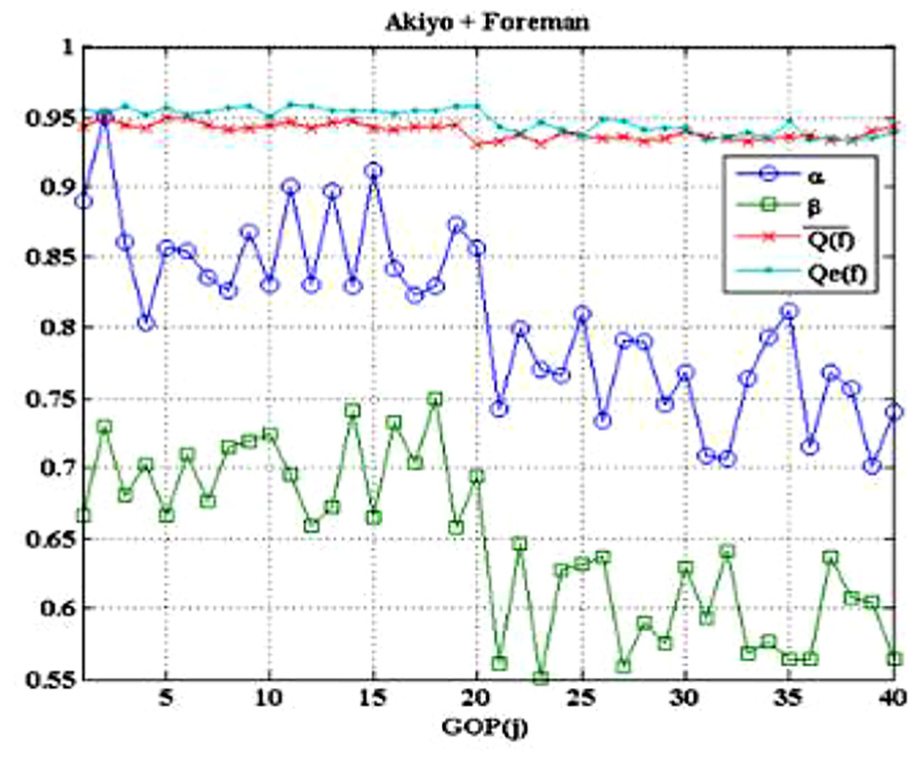
To identify the characteristics of α according to frame loss, the values of α in each GOP to Akiyo and Harbour video were identified. Figure 7 shows the dispersion of Q to the 5th and 10th P frame loss in the Akiyo video in GOP unit. The features of Q to frame loss in one GOP seemed to maintain in each GOP, but the value of α of each GOP to frame loss showed different features.

Dispersions of Q to the 5th and 10th P frame loss in the whole Akiyo video.
Figure 8 shows the dispersion of Q to the 5th and 10th frame loss in the Harbour video. Compared to one of the Akiyo videos, the Q dispersion of successfully received P frames within GOP looks similar, but α is significantly small.

Dispersion of Q to the 5th and 10th P frame loss in the whole Harbour video.
Figure 9 shows a comparison of the average P frame sizes of the Akiyo and Harbour videos.
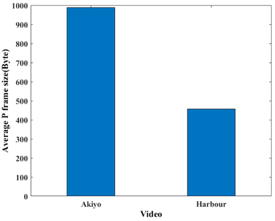
Average data size of P frame in Akiyo and Harbour video.
In other words, when there is a movement, the shape of the object does not change. It only moves to one side; therefore, the difference between the before and after scene is significantly small. Accordingly, encoding is done by coding the small difference. In this regard, the larger the data size of P frame, the higher the prediction amounts. When recovered after loss, it will affect much the video quality. This relation could be used to predict distortion amounts but in this study Q was calculated directly to frame loss. Therefore, this is not the area to be studied in this study but to use it only to explain the difference in size of
In case of I frame loss
I frame loss affects every frame of the GOP. Therefore, when the quality of each frame is predicted by the GOP unit, it is difficult to predict the quality of each frame due to the I frame loss. Figure 10 shows the Q dispersion of the entire GOP when the I frame of the jth GOP was lost. The I frame loss of the jth GOP is related to the one of (j + 1)th frame. If the (j + 1)th I frame is lossless and the jth I frame has loss, the entire jth GOP is copied to the (j + 1)th I frame through the copying algorithm. This is related to losses between I frames, which makes it difficult to predict the frame quality of the entire GOP. In this study, we use the average Q value of GOP to I frame loss, and express it as β. Figure 11 shows the recovery process of I frame loss.
Q dispersion in GOP due to I frame loss.
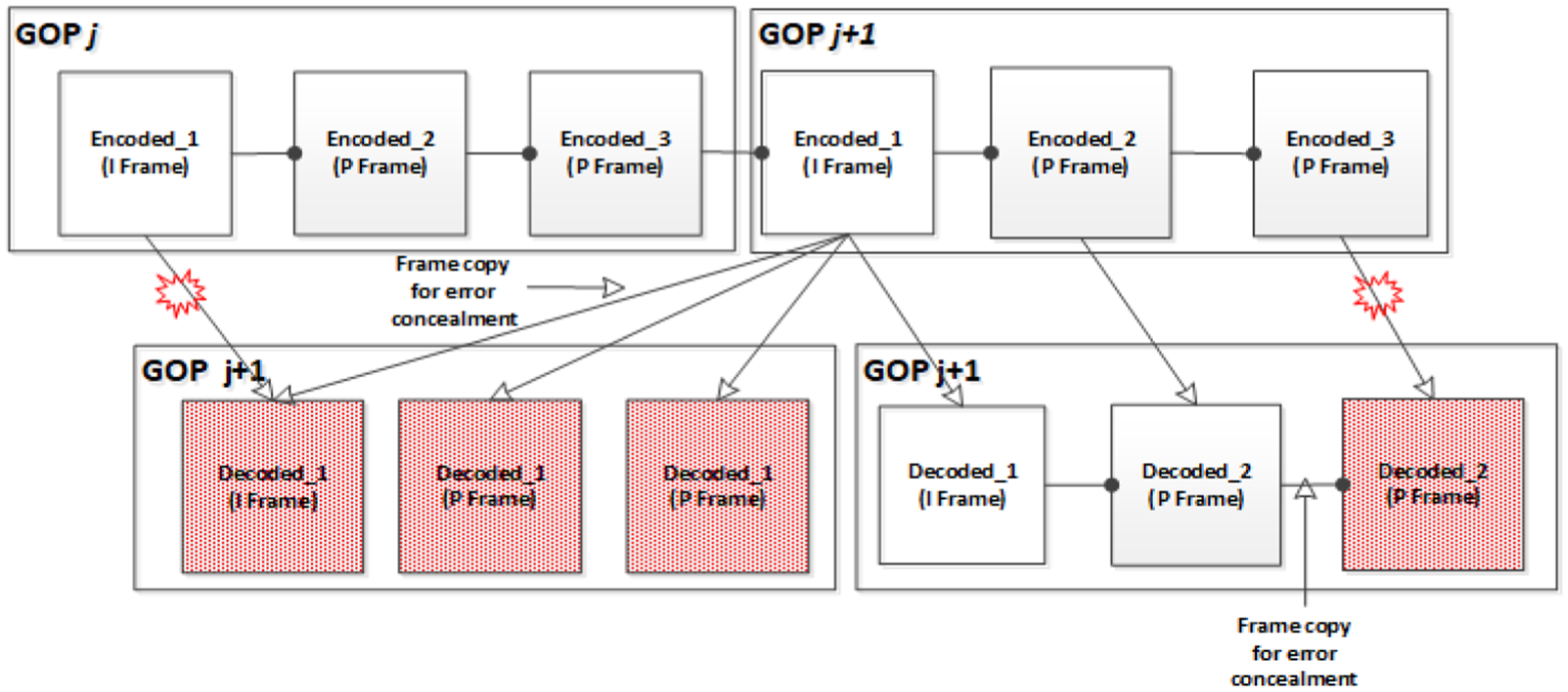
Frame copying concept map on I frame loss in the whole video.
As shown in Figure 10, the Q dispersion of each GOP frame to I frame loss is difficult to predict because Q varies depending on the position of the coped I frame. In this study, the prediction quality of the distortion of the middle frame between the I and P frames is defined as


Based on the overall result of whether the I frame is lost or not, formula (15) could be expressed. Here,

Quality prediction model–based ULP system
Video quality prediction model–based ULP is to find the FEC packet allocation case where
The encoded video monitoring module monitors information about the number of packets of I and P frames. Using packet loss rate and encoded video information, the I and P frame loss rate to the FEC packet case could be calculated. Using I and P frame loss rate calculated by the FEC packet allocation case and

System structure map of quality prediction model–based ULP.
There is only one I frame in GOP; therefore, only one FEC packet allocation method exists. However, for the case of the P frame in the GOP, the FEC allocation algorithm is either allocating FEC packet to every P frame, or to the whole P frames. However, the former method is not effective when the location of lost packet is not identifiable. Hence, we allocate FEC packets to the whole P frame and then calculate the loss rate of each P frame.
As explained earlier, the I frame loss rate is calculated using a binomial that utilizes the I frame packet numbers,

Using equation (17), the frame loss rate of each P frame could be calculated as shown in equation (18)

Figure 13 shows the P frame loss rate calculation concept map according to FEC packet allocation.

Concept map of P frame loss rate calculation.
Performance evaluation
System development and evaluation of experimental environment and capability
To develop a ULP system for a Wi-Fi broadcasting system, this study identified the real network abstraction layer (NAL) unit of each frame in H.264 streaming. Compared to the standard, the start pattern of the I frame in real NAL units was 00 00 01 B3 and that of the P frame was 00 00 01 B6. Figure 14 captured a real packet in a NAL unit and shows real frame header of I and P frames. Based on this information, different FEC rates were applied to each frame. The Wi-Fi broadcasting system creates video data and encodes FEC packets in order to transmit them through AP.

Head structure of the I and P frames in an NAL unit.
Packet loss during transmission is unavoidable, but users may recover a lost packet using FEC decoding technology. A problem arises when expressing this system as it is, and the problem is caused by loss. In this environment, data are transmitted through AP, and different losses occur in different environments. To evaluate video quality, a precise packet loss rate is necessary. Hence, in this study an experimental environment was constructed as follows. A broadcasting server creates encoding and broadcasting packets and transmits data to the FEC & error creating server. The FEC & error creating server creates FEC packets according to the proposed method, adds it to the video, and transmits the video data to users based on the loss rate. This is the method to ensure precise packet loss rate and it is assumed that packet loss occurs randomly. To realize the FEC function, an erasure code based the ZFEC library was used (Figure 15). 36
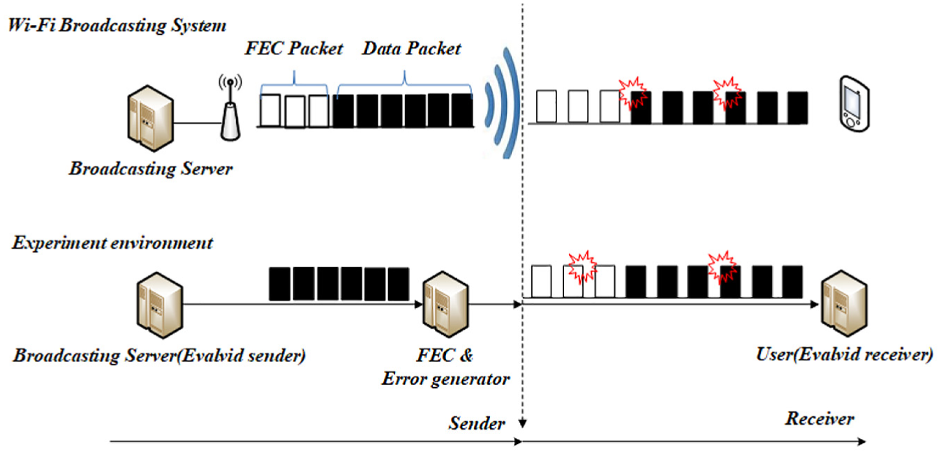
Experimental environment concept map for evaluating performance of Wi-Fi broadcasting system.
Figure 15 shows an experimental structure that corresponds to the composition of the Wi-Fi broadcasting system. Each composition is classified into sending and receiving parts. Table 3 shows the video encoding parameter. For the packet creation, packet transmission, packet receiving, and capability evaluation, EvalVid framework was used. 37 The EvalVid framework was installed in the broadcasting server and users to evaluate video quality about broadcast packet loss.
Encoding parameters for capability evaluation experiment.

GOP: group of pictures.
The scene changing features of the Akiyo and Foreman videos used in the experiment are discussed here. The Akiyo video involves a female announcer sitting and reporting the news. This video indicates no changes except for the eyes and mouth of the woman. After identifying the size of the I and P frames of the entire video, it has the same proportion of I and P frame size in every GOP. The Foreman video is of a male construction worker introducing his work. The background of the video at the beginning does not change but the man changes his gestures. At the end of the video, he disappears and only the work field is being shown. Here, a significant scene change occurs. After identifying the size changes of the I and P frames of the entire video, it was determined that they were larger than those for the Akiyo video because of the scene changes.
The reason why the Akiyo and Foreman videos were chosen for capability evaluation is to identify the validity of the quality prediction model to frame loss by comparing one video with less scene changes to another with more scene changes. Then, based on this experiment, the videos were used to verify the ULP system.
In addition, to identify the quality deterioration coefficient that is proportionally allocated FEC packets, we found that two different scene changing videos are needed. As a result, we are going to identify the characteristics of our proposed algorithm based on scene changes. Figure 16 shows a video screen of the Akiyo and Foreman videos and the frame size of each video.
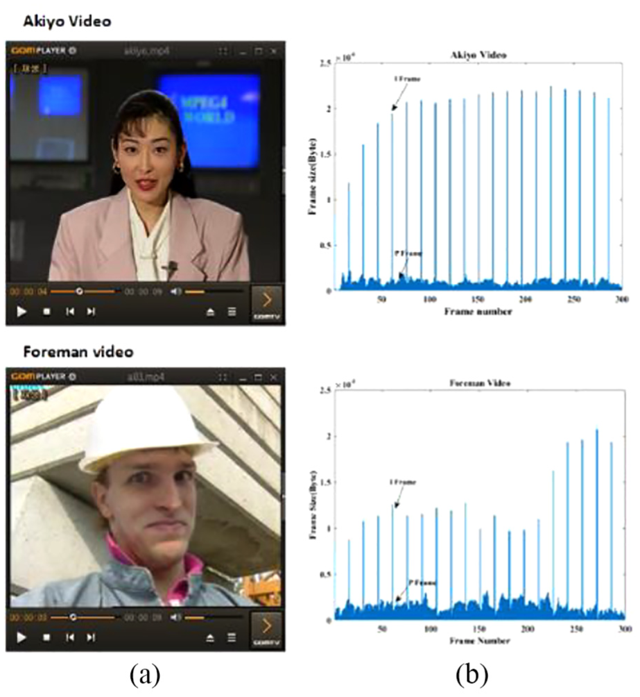
(a) Screen of Akiyo and Foreman videos and (b) frame data size of each whole video.
For the performance evaluation, we compare the suggested
The simulation model is used to supplement the results obtained from the actual experiment and to calculate the theoretical Q(j) according to FEC packet allocation dispersion by making every loss situation theoretically possible in every frame of the GOP. In this study, Q(j) by simulation is defined as
Here,
For example, when the GOP is equal to 5,
Then,

Concept map for
Validity of the quality prediction model
To verify the quality prediction model, characteristics of

The X-axis in Figure 18 represents
To confirm the validity of the quality prediction model proposed in this study,

Using Figures 18 and 19, the validity of the proposed quality prediction model would be identified.
In another example,
We have seen the validity of the proposed algorithm through the values of

Difference between
Because the packet loss rate is smaller, the difference is smaller as well. However, as the loss rate increases, the difference becomes significantly larger. If the loss rate increased by more than 40%, the difference would significantly increase. Even if the difference has increased, the FEC packet could be allocated assuming that the validity of the model is identified.
Validity of the quality prediction model–based ULP system
To identify the validity of the proposed quality prediction model to loss rate of I and P frames, the quality of receiving video to frame loss was identified through experimentation. In this chapter, we are going to identify the quality of receiving video depending on packet loss rate and FEC data packet numbers in order to verify the proposed quality prediction model. Using the Akiyo video, the experiment performed to predict quality dispersion with the proposed algorithm was conducted when the packet loss rate is 10%, 20%, or 30%, and when the FEC packet is 64 or 128 kbps. Figure 21 shows

The Akiyo video is 30 fps. Because the GOP size was set at 15 and the packet size was set to 1024 bytes, the FEC packet of 64 kbps could be used to recover losses of the four packets. The four FEC packets have five patterns for the allocation of the I and P frames. For those five patterns, we calculated
Also, in every
Figure 22 shows

Figures 23 and 24 show

The reason why quality decreases drastically when
Figure 25 shows

From the experiment, the dispersion of
Figure 26 shows


The average of

Predicting video quality is cost intensive. In this study, using the frame information, the values of α and β are predicted. We examined
When allocating α and β dynamically, the average of

Comparison of
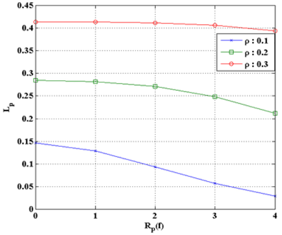
Characteristics of Wi-Fi ULP based on the quality prediction model
To identify the characteristics of the

The size of

Comparison of existing research
In this chapter, existing research on lost packet recovery algorithms and the quality prediction model–based ULP system proposed in this study are discussed. Figure 34 shows the no-recovery, ELP, and Hartanto
30
algorithms at FEC data 64 kbps in the Akiyo video and the average of

Q curves of each loss recovery method in the Akiyo video, when the FEC packet rate is 64 kbps.
The no-recovery algorithm measures the quality of receiving video after loss occurs without the FEC packet. The ELP algorithm equally allocates FEC packets to every packet without distinguishing frame. The Hartanto algorithm assigns different FEC rates to different frame sizes. For the Wi-Fi broadcasting system, we decided to compare the no-recovery algorithm, ELP algorithm, and Hartanto algorithm with
In this article, we implement the proposed algorithm on an embedded board and construct a real Wi-Fi broadcasting system to show its performance. Since the FEC of the Wi-Fi broadcasting system is implemented in the application layer, we will compare it with the Hartanto, ELP, and no-recovery algorithms that can be implemented in related work.
For the ELP algorithm, the selection of k of FEC(n, k) is important, but in this study k was set as the number of packets per second of ELP. Hence, under circumstances where the FEC packet is limited, the ELP and Hartanto algorithms had similar allocation, which in turn resulted in similar receiving video quality. At low values of
Figure 35 shows the no-recovery, ELP, and Hartanto
30
algorithms at FEC data 64 kbps in the Foreman video and the average of

Q curves of each loss recovery method in the Foreman video, when the FEC packet rate is 64 kbps.
Compared to the Akiyo video, the Foreman video has more I frame packets, the quality of receiving video to packet loss showed lower values. In the Foreman video, an average
When
Finally, we compared the Q of ELP, Hartanto, and

Q comparison of ELP, Hartanto, and
Conclusion
With the development of high-performance smartphones, tablet PCs, and laptops, various high-speed network technologies are able to offer real-time multimedia services to users. Consequently, the demand of broadband Wi-Fi technology has been on the rise.
Unlike the unicast-based Wi-Fi system that is used to transmit wireless data to users for multimedia services, the Wi-Fi broadcasting system uses broadcasting packets to offer multimedia broadcasting services to multiple users simultaneously. However, Wi-Fi broadcasting packets do not offer a lost packet protection algorithm at the MAC level or retransmission, and thus packet loss is unavoidable. Hence, additional technology such as FEC is required to recover lost packets.
The multimedia data transmitted through the Wi-Fi broadcasting system are first encoded for effective transmission and then those encoded frames are assigned different roles and features, which in turn resulted in video quality distortion to frame losses. Considering these frame features, recovering lost packets using FEC packets without distinguishing frames is not an effective method to improve video quality. Therefore, ULP has been proposed.
If the quality of receiving video after a certain frame recovery could be predicted, lost packets would be effectively recovered based on the predicted quality of the video. Therefore, this research has performed modeling of the predicted quality of receiving video to frame loss in a Wi-Fi broadcasting system. To propose a quality prediction model to account for frame loss, we first analyzed the quality deterioration features on the loss occurrence of an I frame and then proposed a quality prediction model that could be applied to ULP. In addition, we proposed a quality prediction model for frame loss and a ULP algorithm based on frame loss probability.
To verify the performance of the proposed algorithm, the quality prediction model–based ULP system was realized in a Linux-based embedded board. The realized algorithm was first evaluated for validity through the actual experiment and simulation. To examine the validity of the proposed quality prediction model, an experiment was conducted to determine the loss rate of the I and P frames and the allocation of FEC packets.
The average quality of the proposed algorithm was different for various loss rates of I and P frames. Through the experiment, the validity of the algorithm as a quality metric of the loss rate of the I and P frames was examined. Then, the algorithm was examined through the experimental and simulation results for FEC packet allocation. This study predicts the quality according to frame loss with a simple calculation; therefore, two different videos were played to evaluate the quality when a quality deterioration coefficient was fixed to frame loss, by adaptively calculating the coefficient.
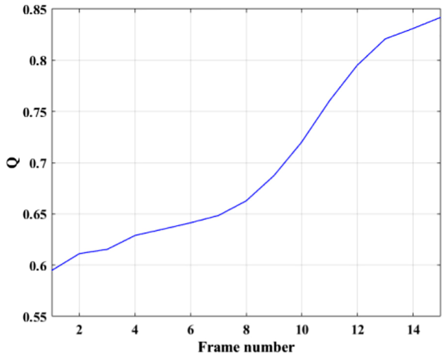
Finally, the algorithm was compared to the ELP and Hartanto algorithms, which are existing lost packet protection techniques. For the Akiyo video, the quality of receiving video utilizing the proposed algorithm showed good results. In particular, when the packet loss rate was 25%, the proposed algorithm showed a Q improvement of 0.3 compared to Hartanto. The 0.3 improvement means that the subjective video quality has been improved from poor to good. In addition, for the Foreman video, Q was improved by an average of 0.12 to every packet loss rate. In particular, when
While predicting the receiving video at the GOP level, the success of the transmission of the I frame decides the difficulty of the video quality prediction model. This research used a simple method to predict the quality of GOP to I frame loss. However, consecutive losses of I frames in experiments have drastically decreased the capability of receiving video. In addition, in the existing studies on ULP, researchers have designed packet transmission techniques for certain multimedia data and evaluated them through simulation, which made it difficult to find a comparison model with the one proposed in this study that was designed in the Wi-Fi-based broadcasting system.
Multimedia data have become high-capacity and Wi-Fi techniques have become high-speed. In this circumstance, effectively transmitting high-capacity multimedia data would be challenging. Hence, this area might be classified into network technology and multimedia data compression techniques for future research.
Footnotes
Handling Editor: Pascal Lorenz
Declaration of conflicting interests
The author(s) declared no potential conflicts of interest with respect to the research, authorship, and/or publication of this article.
Funding
The author(s) disclosed receipt of the following financial support for the research, authorship, and/or publication of this article: This research was supported by Basic Science Research Program through the National Research Foundation of Korea (NRF) funded by the Ministry of Education (2014R1A1A2009092).