
Abstract
In the mobile radio-frequency identification system, the accuracy and rapidity of tag recognition are undergoing great challenges. In this article, we proposed a novel tag anti-collision identification method based on tags’ priority called RPA in the mobile radio-frequency identification system. The algorithm sets the priority of recognition according to the sequence of tag entering the recognition area. The reader does not recognize the tags with low priority until the ones with high priority have been identified totally. The experimental results show that when the tags’ moving speed is lower than 4 m/s, the system can identify the total tags without loss, and the efficiency and identification speed can reach 73.7% and 762 tags per unit, respectively.
Introduction
With the rapid development of Internet of Things, more and more people pay more attention to radio-frequency identification (RFID) technology 1 which is one of the most important technologies in data acquisition. A complete RFID system includes RFID reader, RFID tags, and application server. According to the different ways of energy supply, RFID tags can be classified into three types: active tags, semi-active tags, and passive tags. Usually, low-cost passive tags are preferred in a larger number of tags’ applications. In the total identification process, if there are no new tags moving into or leaving the identification area, this kind of RFID system is called a static RFID system. Otherwise, the system is called the mobile RFID system. 2 In an RFID system, if multiple tags respond to the reader’s acquisition, the signals will be mixed up together which is called tag conflictions. In this confliction case, the reader cannot identify any of the conflicted tags. At present, there are many anti-collision protocols to solve the conflict problem in a static RFID system.3–8 But in many cases the objects attached with RFID tags move along a certain path at a certain speed. This kind of mobile RFID system can be applied to airport pedestrians or luggage monitoring. For example, the RFID-based baggage processing system in Hong Kong International Airport can deal with about 40,000 pieces of baggage every day.
If the objects move too fast or the recognition area is too short, the tags will move out of the recognition area without identification, which leads to tag loss. So tag loss rate is one of the most important indexes in the mobile RFID system. However, most existing anti-collision protocols are not suitable for mobile RFID systems. These methods hold that tags are stationary in the recognition area. Therefore, many researchers focus on how to identify tags accurately, as fast as possible and with low tag loss rate in the mobile RFID system.
For the subject of this section,9–11 the main contributions of this article are shown below. First, we establish a tag arrival model and propose a new adaptive estimation method of tag arrival rate. Second, the article puts forward a mobile tag anti-collision method based on round priority (RPA) which solves the collisions between the first coming tags and subsequent coming ones. The simulation results show that our proposed method can identify tags without tag loss when the tag moving speed is not higher than 4 m per second and the length of the conveyor belt is 3 m. The method we proposed is superior to Q algorithm 12 and G2-CDFSA.
The rest of the article is organized as follows. In the second section, we survey the RFID tag identification process and discuss several important tag identification methods in the RFID system. We discuss the tag arrival model and present our identification method, namely, RPA, in the subsequent section. Then simulation results are provided. Finally we conclude our article.
Background and related work
A lot of research has been done on anti-collision algorithms for static RFID systems. These algorithms can be roughly divided into two categories: deterministic algorithms based on tree structure (which is called tree-based algorithms) and probabilistic algorithms based on ALOHA (which is called ALOHA-based algorithms).
The main idea of the tree-based deterministic algorithm is that the tag ID is decomposed into a binary tree from the highest bit. Non-leaf nodes in the binary tree present the prefix of tag ID. The leaf nodes correspond to a tag ID. In order to identify a tag, the algorithm should traverse the binary tree to find a leaf node. This kind of algorithms, such as binary splitting tree (BST) and query tree (QT), will traverse the whole search space, so no tags will miss being read. When the tag IDs have fewer bits, these algorithms can quickly and accurately identify tags without tag loss. But, with the increase of ID digits, tag recognition delay will increase rapidly. So these methods are not suitable for a low-latency system, such as real-time systems or mobile RFID system. On the other hand, these kinds of algorithms have an assumption that the population of tags will not change in the whole identification process.
ALOHA-based algorithms are time division multiplexing (TDM) methods. These protocols divide the recognition time into a lot of time slots, and each tag randomly selects a time slot for information transmission. These methods overcome the disadvantages of tree-based methods and hence are suitable for the mobile RFID system. ALOHA-based algorithms go through several stages: slotted ALOHA (SA), frame slotted ALOHA (FSA), and dynamic frame slotted ALOHA (DFSA). In SA, tags contend the time slots randomly. In FSA, multiple time slots make up a frame, and tags select the time slots in a frame randomly. The time slots in a frame (known as frame length) will not be changed during the identification process. At the beginning of identification, the reader will broadcast a parameter of frame length denoted by l, and tags will randomly select a time slot in it. If a time slot is occupied by one tag, this time slot is called the successful time slot. The tag in the successful time slot can be identified successfully. If a time slot is occupied by two or more tags, this time slot is called the collision time slot and none of the tags can be identified. If no tag selects this time slot, this is called the idle time slot (or empty time slot). If a tag is successfully identified in this frame, this tag will be changed to the silent state and no longer participates in the subsequent identification process. If a tag is not identified because of confliction, this tag will attend the subsequent identification until it is identified. In DFSA algorithms, the frame length will change according to the unidentified tag populations. Many research results show that when the frame length is equal to the number of tags, the system can achieve the optimal identification efficiency. Therefore, the research on DFSA focuses on how to estimate the number of unidentified tags and then change frame length according to the estimation results, such as Schoute’s method, Vogt method, and MAP method. Schoute’s method 3 estimates unidentified tags by n_ui = 2.39 × n_c, where n_c is the number of collision time slots in the previous frame. Although the estimation error in this method will be very high in a large number of tag environments, it is very simple and has a low computational complexity. Vogt’s method 13 used the minimum absolute distance between the expected value of three types of time slots and their true value to estimate tag quantities. This method needs searching the whole tag number set to find the minimum value. When the tag number varies in a large region, the time for searching the extremum will be very long. The maximum a posteriori (MAP) method 14 estimates tag numbers with the MAP probability method, and this method has a lower estimation error rate. But it needs more complex computation and more load. In industrial applications, EPC Class 1 Generation 2 (EPC C1G2) protocol 15 uses the Q algorithm to determine the frame length. These algorithms mentioned above work under a common condition that all tags are stationary until the identification process ends. The frame length setting mechanism still does not take moving tags into consideration. So in the mobile RFID system these methods cannot work well and the system cannot achieve high efficiency.
In Chen 16 and Alcaraz et al., 17 the FSA algorithm is applied to the mobile RFID system. The tag loss rate of the system can be lower than a certain threshold under certain condition. But the frame length of this method cannot change dynamically, and the application scope is limited. In Vales-Alonso et al., 18 Markovian model is used to analyze and calculate the tag loss rate of the FSA algorithm in the mobile RFID system. When the number of tags increases, the computational complexity increased. So the application scope of this method is also limited. Ding and Lei 19 proposed a new anti-collision algorithm based on priority aversion. All the tags should reserve the time slot first. If two or more tags select the same time slot, the tag with the highest priority will be identified in the reading stage. This algorithm can improve the throughput. When the conflicted tags have an approximately equal energy, the tag with high priority also cannot be identified.
In this article, we consider such a mobile RFID system shown which includes one RFID reader and a lot of mobile RFID tags in Figure 1. Mobile tags move along a specific path, for example, the conveyor belt, at a speed of v. Assuming that the distance of the path in the recognition region is denoted by d, the longest time for the tag in the recognition area is d/v.
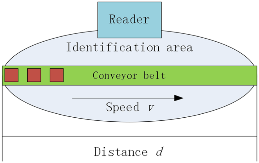
Mobile RFID system model.
First, in such a system, the number of tags which are moving into the recognition region is unknown in advance. If the static RFID anti-collision protocols which are mentioned above are still adopted, the optimal recognition efficiency is hard to be obtained. Second, the tags that first enter the recognition area have a higher probability to leave the area, so these tags should have a higher priority to be identified. In order to solve the collision, we should improve the static anti-collision algorithm.
We adopt DFSA as the basic anti-collision protocol. Suppose that there are n tags needed to be identified, and the frame length is denoted by l. Tags can randomly and independently select time slots, so the number of tags allocated to the time slots is binomially distributed with n Bernoulli trials and 1/l occupied probability. Therefore, the probability of finding r tags in a given time slot can be described as

After a reading cycle, the reader can collect statistics of the number of idle time slots, successful time slots, and collision time slots. Frame length can be reset according to the statistics and the new coming tags.
The RPA method
The frame length setting mechanism
In many static anti-collision algorithms, the number of tags is exactly predicted first, then the frame length is set to be the same as tag quantity, and therefore the system can achieve the optimal identification efficiency. However, in practical applications, the number of time slots should be the integer power of 2 because of the restriction of the hardware structure. So we do not need to estimate tag quantity as exactly as possible, but to estimate which range the tag number belongs to. The RFID reader can set the frame length according to the range.
Using equation (1), we can obtain the expectation quantity of the idle time slots


In our article, we consider that the durations of the idle time slot Te, successful time slot Ts, and collision time slot Tc are not equal, so the expectation efficiency in the ith frame can be expressed as

We adopt the EPC C1G2 standard as our basic technology, and therefore Te, Ts, and Tc should be 165.22, 967.95, and 242.92 μs, respectively. 8 In order to obtain the optimal expectation efficiency, we simulate the relationship between tag numbers and efficiency under different frame lengths as shown in Figure 2.

Tag number versus expected efficiency under different frame lengths.
It is hard to exactly calculate the value of the intersection point in these curves, so we use the graphical method to obtain the solutions shown in Table 1.
System identification efficiency with the value of tag number n and frame length l.

It is shown in Table 1 that when the frame length varies from 8 to 1024, the expected efficiency varies between 0.7265 and 0.7486. If the estimated tag number falls within a certain range, we can obtain the corresponding frame length according to Table 1 for the next reading frame. If the values in Table 1 are put into the memory of the reader, the speed of obtaining the new frame length will be greatly improved. Using this method, we do not need to exactly estimate the number of unidentified tags, but to estimate the range of unidentified tag number. Hence, in the later discussion, we adopt a simple, low-computational complexity method to estimate the tag number.
Adaptive tag arrival rate estimation
In the mobile RFID system, mobile tags can enter or leave the identification area. The number of new arrival tags is unknown in advance. So we should use some mechanism to estimate the arrival rate of tags. We separate the reading process into the frame, in which the reader send quarries to the tags and tag reply. The processes are shown in Figure 3.
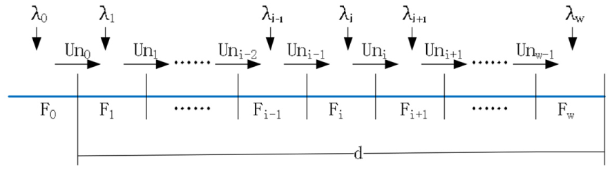
Tag arrival model.
The lengths of different frames are different according to the different unidentified tag numbers in the frame. Suppose that w frames can be contained in the recognition area with the distance d and Fi represents the ith frame. F0 is called the initial frame, in which the reader does not work, and tags are ready to be identified. λi represents the number of arrival tags per unit time (also called the arrival rate) in the ith frame. In order to simplify the analysis, we stipulate that the new arrival tags in the ith frame cannot participate in the identification of the ith frame. These new arrival tags will participate in identification in the (i + 1)th frame. Uni represents the number of tags transferred from the ith frame to the (i + 1)th frame. The value of Uni includes two parts: one part is the number of unidentified tags Nc(i) that represents unsuccessfully identified tags in the ith frame. The other part is the number of new tags new(i) that are newly entered into the identification area during the identification process of the ith frame. Therefore, Uni can be expressed as follows

When the reader ends the ith frame, the reader can collect the statistics of idle time slots SlotE(i), successful time slots SlotS(i), and collision time slots SlotC(i). In order to simplify the calculation, we adopt Schoute’s method to estimate the number of collision tags, so

In order to calculate new(i), we need to know the duration of Fi and the arrival rate λi. We use l(i) to represent the duration of Fi, so

In the mobile RFID system, λi is unknown in advance. In order to obtain the arrival tag rate, we should estimate the arrival tags during the ith frame. Next we will discuss the estimation method of arrival tags.
At the end of the ith frame, we can approximately estimate tag number N(i) in the ith frame using the statistical results

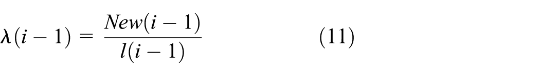
Therefore, we can obtain the new arrival tags new(i – 1) and the arrival rate λ(i – 1) in the (i – 1)th frame

Usually, the arrival of tags often has a certain trend. For example, in the logistic system, at the beginning the quantity of goods is small, then increases gradually, and finally decreases. According to the continuity principle, we suppose that the tag arrival rate of the ith frame is approximately the arrival rate of the (i – 1)th frame. That is

Next, according to Table 1, the reader can select the new frame length using U(i).
This method can easily obtain the tag arrival rate, although it requires the reader to store some parameters such as U(i) and l(i) in the ith and the (i – 1)th frame.
F 0 is called the initial frame, in which the reader does not work and the tags in this frame are ready for being identified in the next frame. U(0) only includes the new arrival tags in F0.
The RPA method
After solving the problem of tag arrival rate, we start to solve the confliction between new arrival tags and the previous ones. In general, we can think that the earlier entered tags are more likely to move out of the recognition area first and these tags have high priority to be identified. In order to ensure that the tags which first enter the identification area are first identified, we adopt the round priority strategy to avoid confliction.
Round refers to the process of starting to identify a set of tags until completing the identification of this set of tags. During the identification process of a certain round, new arrival tags will not attend this round to be identified. Each round contains multiple frames, and each frame contains multiple time slots. At the beginning of identification, the reader broadcasts two parameters: beginning of round and frame length. Each active tag in the recognition area selects the time slots randomly. The tags reply information to the reader at the selected time slots. This process is the same as DFSA. After the end of this frame, if some tags are not identified because of collision, the reader will broadcast a new parameter (not including the beginning of the round) of frame length to tags and the unidentified tags in the previous frame will attend the new frame. New arrival tags will not attend this frame until this round ends. So the tags in the recognition area will be divided into two priority levels shown in Figure 4.

Identification process based on round priority.
In order to ensure the tags in the first round to have high priority to be identified, the new entered tags during the first round will remain idle until the first round ends. This kind of method completely eliminates the contention between new tags and the old ones.
It is assumed that the tags are ready to be identified before the first round. The tags in the first round are all identified in a certain time denoted by latency(1). The distance of the reader recognition area is d, and the speed of the conveyor belt is v, so the maximum detention time of a tag in the recognition area is d/v. If the value of d/v is less than latency(1), we can consider that the tags will move out of the scope of recognition before the first round is finished, which will lead to tag loss. If the value of d/v is greater than latency(1), the second round will start. At the beginning of the second round, the last tag in the first round has moved to position v × latency(1). We assume that the duration of the second round is latency(2). If the value of (d/v – latency(1)) is less than latency(2), we can consider that the tags will move out of the scope of recognition before the second round is finished. Otherwise, the next round will start, and so on. The flow chart is shown in Figure 5.

Workflow chart of RFID reader and tags.
Simulation results and analysis
Simulation results of arrival rate
In order to assess the accuracy of prediction and the efficiency of the system, we define the following indicators:
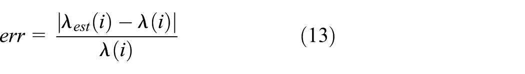
The estimation error rate of tag arrival is denoted by err
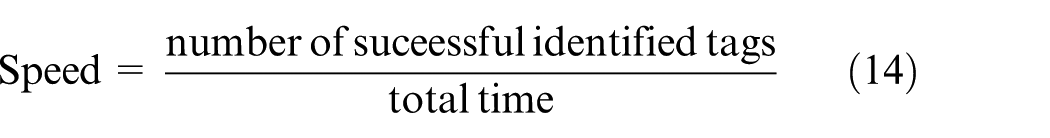
The identification speed of the system is defined as
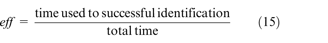
The system efficiency can by calculated by
First, we assume that the arrival rate
The estimation error rate and efficiency under different

From Table 2, we can obtain some conclusions. When the arrival rate
Second, we assume that
From Table 3, we find that, when
The estimation error rate and efficiency under different steps of

With discussing the arrival rate, we only consider the tags moving into the recognition area, so next we will discuss the tag departure.
Simulation results of RPA
In order to eliminate the collision between old tags and the new ones, we proposed the RPA method discussed in the previous section. In the first round, we use the pseudo-code in Algorithm 1 for simulation.
Algorithm 1.
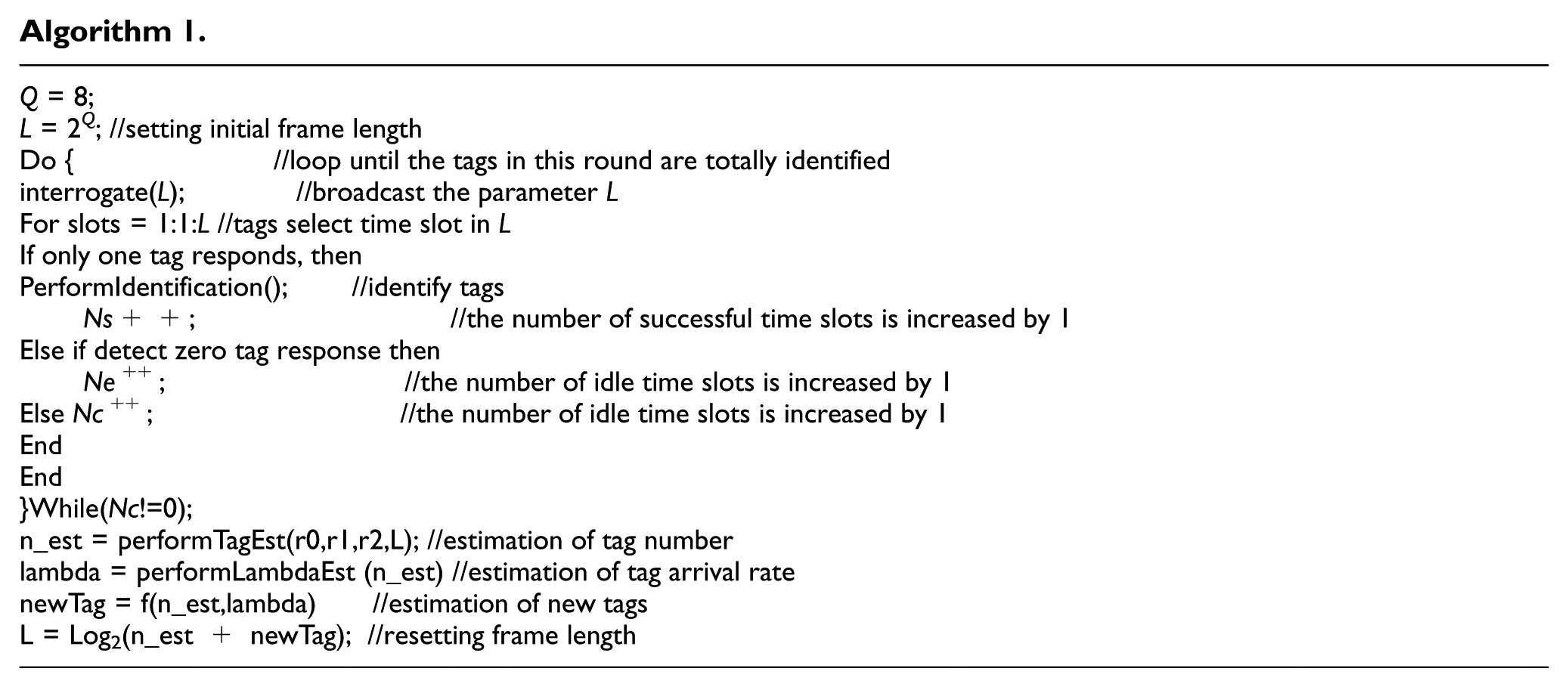
Computer simulation experiments are performed using MATLAB 2015b to evaluate the RPA. We suppose that the speed of the conveyor belt is v, and the length of the conveyor belt is d. If the tag arrival rate is constant and d is 3 m, v is 3 m/s, the efficiency, speed, and tag loss rate of the RFID system are shown in Table 4.
The efficiency, speed, and tag loss rate underdifferent

When
Next, when we change the speed of the conveyor belt, the performance of the RFID system will change too.
The results in Table 5 are under the condition that the arrival rate is 720 and the length of the conveyor belt is 3 m. If the speed of the conveyor belt is higher, the time that the tag stays in the recognition area is short, so the tag loss rate will be higher. In order to make the RFID system stable and useful, the speed of the conveyor belt should not be more than 4.
The efficiency, speed, and tag loss rate underdifferent

Next, we will compare RPA with the EPC C1G2 Q algorithm and G2-CDFSA proposed by Chen. 16 The results are shown in Figure 6 when v is 3 m/s, d is 3 m, and the tag arrival rate is 720.
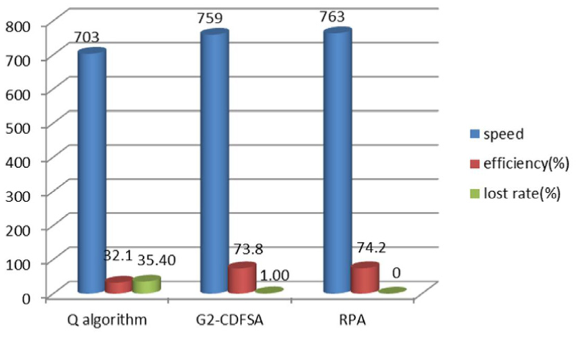
Comparisons of the three different methods.
It can be seen from Figure 6 that the speed, efficiency, and tag loss rate of RPA are superior to those of the other two methods. All the values are average of 1000 experiments.
Conclusion
In this article, we proposed the RPA method for mobile RFID systems. RPA is based on the round priority method which totally eliminates the collision of old tags and the new ones. Compared with the existing approaches, namely, Q algorithm and G2-CDFSA, we find that RPA produces a lower tag loss rate, a high identification speed, and a high system efficiency when v is 3 m/s, d is 3 m, and the tag arrival rate is 720. Therefore, the proposed RPA is suitable for mobile RFID identification systems. The implementation of this protocol needs the tags to record priority, and the tags should respond to the reader’s request according to priority. These make the tags’ structure complex. On the other hand, the instruction set of the reader should add the priority instruction. But, with the rapid development of hardware technology, these two aspects are not hard to implement.
Footnotes
Handling Editor: Daming Zhou
Declaration of conflicting interests
The author(s) declared no potential conflicts of interest with respect to the research, authorship, and/or publication of this article.
Funding
The author(s) disclosed receipt of the following financial support for the research, authorship, and/or publication of this article: This research was supported by the National Nature Science Foundation of China under Grant No. 61363016, the Nature Science Foundation of Inner Mongolia Antonymous Region under Grant Nos 2015ms0626 and 2015ms0605, the Project of Scientific Research Foundation of Department of Education of Inner Mongolia Antonymous Region under Grant No. NJZY17057, and the Basic Research Foundation of Inner Mongolia Agriculture University under Grant No. JC2015008.