
Abstract
A hardware-in-loop real-time multi-simulation platform system is established based on data fusion approach, and the vehicle closed-loop control system is obtained based on “driver–central controller–motor drive system–vehicle dynamics,” on which the control strategy of wheel-motor-driven multi-axle vehicle is verified. Data among the platform are transformed based on FlexRay bus. A simulation experiment of electrical vehicle dynamic performance is tested by real driver in real time to analyze whether vehicle dynamic performance is performed based on the multi-platform. The results indicate that the hardware-in-loop real-time simulation system can effectively verify the reliability of control strategy, and the data fusion of multi-simulation-platform works well.
Introduction
It is an important method to realize electrical vehicle driven with wheel motor. The technology of wheel-motor-driven electrical vehicle is developed rapidly at present. 1 Researches on the aspect of its economy and driving stability control are multiple, but few on the multi-axle electrical drive vehicle; only simple solution and dynamic simulation are introduced.2–4 Only some similar schemes of simple dynamic simulation are researched in the domestic, while only simple solution is introduced abroad. The usual way of studying electrical vehicle is building vehicle dynamic model and control system model adopting off-line simulation, and taking the simple motor characteristic curve to simulate motor performance. The simulation above is running in an ideal environment, ignoring the influence of the model precision of driving motor on the vehicle dynamics performance. Compared with the off-line simulation, hardware-in-loop (HIL) real-time simulation with a real vehicle integrated controller, combined with real driver control equipment, can not only greatly improve the reliability of the simulation but also further test hardware and software system of the real vehicle integrated controller.5,6 Therefore, the use of HIL real-time simulation is an effective way to study wheel-motor-driven multi-axle vehicle traffic control research.7,8 This article calculated vehicle dynamics based on a four-axle monorail vehicle models. A driving control strategy of wheel-motor-driven multi-axle vehicle based on yaw moment was designed. A real-time multi-simulation platform is established based on data fusion of FlexRay. A real-time simulation experiment with driver-in-loop was performed based on real controller-in-loop co-simulation platform constructed with RT-LAB and Vortex, to study the vehicle dynamic performance under driver controlling and test the control strategy of real controller.
Vehicle dynamics model calculation is based on a four-axle monorail vehicle model. A torque coordinated control method based on bi-level optimization is designed, which includes torque prediction distribution control and the optimal slip ratio control. Direct yawing moment and additional torque are initially implemented in eight driving wheels through prediction distribution control, the single optimal control of rotary torque output is achieved through the optimal slip ratio control, and the stable operation of the vehicle control is realized. In the optimal slip ratio control, an optimal slip ratio controller is designed based on sliding mode control theory to achieve real-time estimation on optimum wheel slip rate. The simulation experiment with driver-in-loop was performed based on real controller-in-loop co-simulation platform constructed with RT-LAB and Vortex, to study the vehicle dynamic performance under driver controlling and test the control strategy of real vehicle integrated controller.
Modeling of driving system
The structure of wheel-motor-driven multi-axle vehicle
The structure of wheel-motor-driven multi-axle vehicle is shown in Figure 1. Eight wheels are driven with wheel motor, no mechanical connection is seen between each electrical wheel, and independent drive controlling can be realized. The eight-wheel motor is the same permanent magnet synchronous motor.

The structure of wheel-motor-driven multi-axle vehicle.
A flexible transmission of power was realized by wheel-motor-driven multi-axle vehicle. The control instruction was transferred directly from the central controller to driven motors through the bus, to adjust torque output on both sides to meet the demands of yawing moment vehicle. So, the steering radius was changed and steering ability of vehicle was improved. Figure 2 shows the driven system structure mentioned above.

The structure of driven system.
Mathematical modeling of multi-axle vehicle based on yaw velocity
The movement of the vehicle can be regarded as plane motion of a lumped mass rigid body, ignoring roll motion and longitudinal movement of the vehicle. A single-track model of four-axle vehicle is built as shown in Figure 3.

A single-track model of four-axle vehicle.
Tire lateral force equilibrium equation is

The momentum equilibrium equation around Z-axle is

where
Tire lateral force can be calculated by the formula as follows

where

Substituting equations (3) and (4) into equations (1) and (2), assuming

where
We can know according to the principle of linear superposition
where

In the meanwhile, influenced by the adhesion coefficient, the tire lateral force under different road conditions must be met with equation (8)9,10

When the centroid sideslip angle is small, then

The control strategy
Torque pre-distribution control strategy
Ideally, a driving force evenly distributed to each wheel. But on poor road conditions, vehicle load for each wheel is varied and not identical. The wheels are easy to sliding, which seriously affect the vehicle control performance. 11 Therefore, it is necessary to adjust driving rotary torque according to the vehicle running state in real time. Here, the adjustment of torque output is made mainly in the following three levels.
1. Calculating the total target torque according to the gas pedal or braking pedal, and average-assigned to each driving motor initially.
where
The given torque of each motor is

2. Expected yaw moment

The given torque of each driving motor on left and right is

3. We reduced the given torque of driving wheel which had slipped, and average-assigned the reduced torque to the other driving wheel on the same side in order to ensure the total driving torque and yaw moment unchanged.
The reduced torque

where

where
Torque distribution control based on the optimal slip rate
As biggest stress of a single wheel is considering in top-level control strategy, it is not the key point here in yawing moment pre-allocated. When driven torque of four wheels is given the same on the same side, there will be individual wheel slip due to the difference between front axle load and road roughness, affecting the vehicle yawing moment demand. At the same time, the transition of the wheel slip will also accelerate instability caused by vehicle and tire wear.
The optimal slip ratio control, we studied in this article, is to integrate the acceleration slip regulation (ASR) into direct yawing moment distribution control (DYC). By monitoring the sliding state of each driving wheel, the torque output of each driving wheel is controlled in real time, so that the sliding rate of the driving wheel is kept near the optimal point, thus realizing the optimal control of single wheel torque after pre-allocation of yaw torque.
The anti-skid control system structure is shown in Figure 4. Anti-skid control mainly includes four parts: the optimal slip ratio estimation, wheel slip rate estimation, road adhesion coefficient estimation, and the optimal slip ratio sliding mode controller.

The structure of anti-skid control system.
The estimation of the optimal wheel slip rate point is one of the most important key technologies of optimal slip ratio control. The method based on the tire-road friction coefficient—wheel slip rate curve estimation—is being popularly used in this study. 12 The method is based on the identification of tire-road friction coefficient, by drawing curves, and compared with typical ride under the condition of curve, to estimate the current pavement under the condition of the optimal wheel slip rate. Tire-road friction coefficient identification method is the optimal algorithm based on Levenberg-Marquardt (LM) to estimate road adhesion coefficient. Burckhardt and colleagues have fitted curve of several kinds of typical road surface on the basis of a large number of test data, as shown in Figure 5, in which the tire-road friction coefficient of the accessory roller skating turn rate always increases first and then decreases; a maximum tire-road friction coefficient of the slip rate is called the optimal slip ratio.
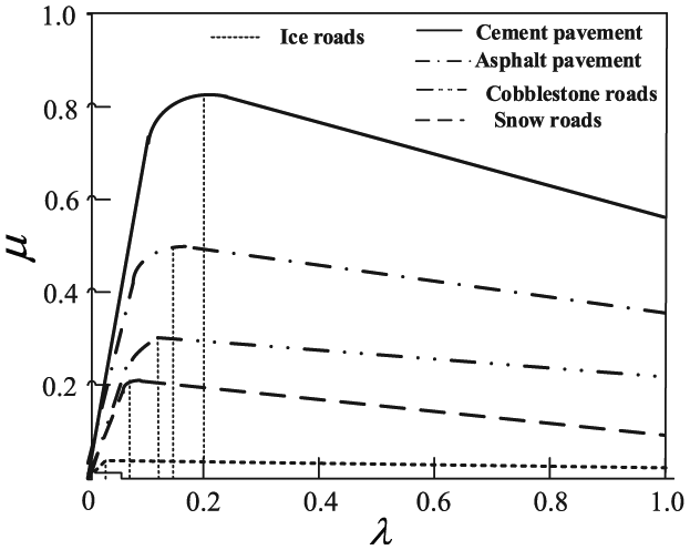
The relationship of µ–λ.
There are several road surface adhesion coefficients,
Several typical parameter values of pavement types.

On the basis of recognition of the current road adhesion coefficient, fuzzy algorithm is used to estimate the current road conditions of the optimal slip ratio value compared with typical road adhesion coefficient according to the similar degree.
HIL real-time simulation
The structure of HIL real-time simulation platform
The structure of HIL real-time simulation platform is shown in Figure 6.
The driver simulation station is combined with a Logitech game control system and a real vehicle driver control box, which is mainly used in driver signal acquisition and transmission.
The DSP TMS28335 is used as main control chip of real vehicle controller, with digital signal interface, analog signal interface, and FlexRay interface, working to calculate the vehicle control strategy.
The RT-LAB simulation platform simulated the wheel motor and its drive control system. The motor model was established by the data fitting of real motor experiment.
Real-time vehicle dynamical simulation was performed based on Vortex. We loaded the given torque, calculated by RT-LAB, to vehicle tire model in Vortex through FlexRay bus after efficiency corresponding conversion.
System operation parameters were shown in real time based on state parameter monitoring system in dSPACE simulation platform.

(a) Structure of HIL real-time simulation platform and (b) HIL real-time simulation platform.
The rapid control prototyping based on dSPACE.
dSPACE real-time simulation system is a set of software and hardware working platforms based on MATLAB/Simulink control system development and semi-physical simulation developed by German company dSPACE, realizing a completely seamless connection with MATLAB/Simulink/RTW. RT-LAB is a brand new model–based engineering design application platform.13,14 It can directly apply the mathematical model of dynamic system established by MATLAB/Simulink to real-time simulation, control, testing, and other related fields.
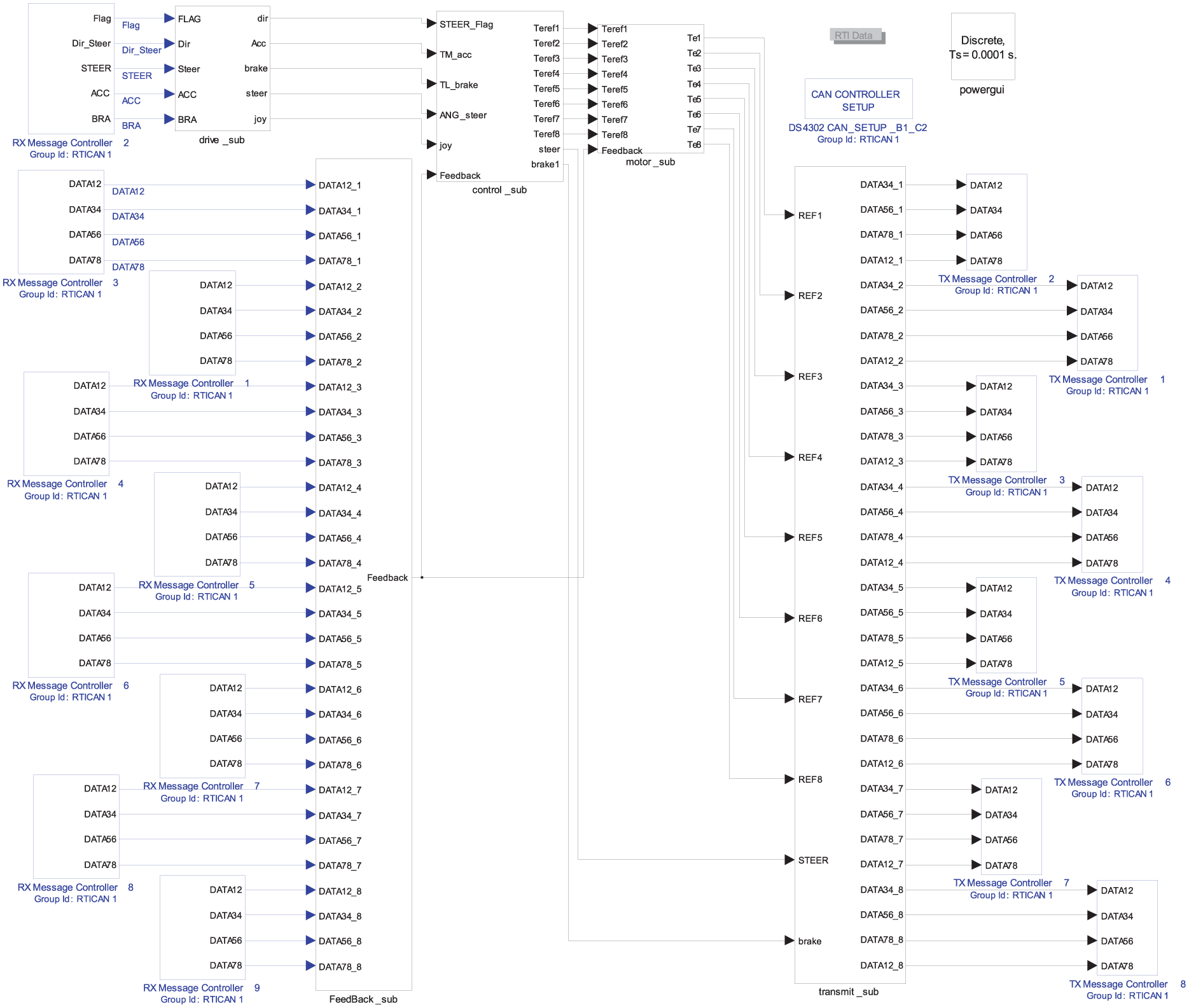
In the process of real-time simulation, the operation information is transformed through simulated driving device such as steering the wheel and driving the pedal and brake pedal by driver.15–17 The driver collection box will collect analog signals into digital signals to the controller (dSPACE simulation system). The controller is running control algorithm (including motion tracking control algorithm, torque coordination control algorithm, and the state of the corresponding parameter estimation algorithm) according to the driving input, combined with the state of the feedback information of vehicle real-time dynamic model simulation in Vortex. The controller solves the torque instruction and transfers it to RT-LAB simulation system (running motor and its control system model) by bus. RT-LAB simulation system sent the actual output torque value in real time to the dynamic model of vehicle in Vortex real-time simulation system, to drive the vehicle. The real-time vehicle dynamics model is running in Vortex system and receives the driver operation and torque signal instructions at the same time, simulates the vehicle movement, and feeds the vehicle state information back to the vehicle controller, forming a closed-loop control system.18–20 Interactions can be operated through ControlDesk software with vehicle model of Vortex, such as online tuning parameter, condition monitoring, and data storage. ControlDesk is the dSPACE experiment software for seamless electronic control unit (ECU) development. It performs all the necessary tasks and provides single working environment, from the start of experimentation right to the end. Based on the above process, the information transmission among simulation platforms is implemented on FlexRay bus. Each node receives control instructions through the bus and returns the state response and running parameters to the bus, and the communication data between the nodes in the bus are monitored and recorded in real time to obtain the experimental data.
The real-time simulation of HIL is divided into two parts. The first step is to carry out rapid control prototype simulation based on the dSPACE simulation system, in which the dSPACE system is used as the controller to run the control algorithm program. DSPACE RTI (Real-Time Interface) was used to establish the control system model. Through repeated simulation tests, the parameters of the control system were adjusted online to ensure the reliability and real-time performance of the concontrol system. In the second step, the generated code of the verified model is downloaded to the real vehicle central controller to replace the dSPACE simulation system and carry out the real-time simulation test of the controller in the loop.
Simulation and analysis of the torque pre-distribution control
The HIL real-time simulation platform can test different dynamical control algorithms considering the influence of driver input, which can evaluate the vehicle performance under different control strategies.
Experiments on the vehicle continuous acceleration, turning, and braking on good roads and slippery pavement were performed, shown in Figure 8. Total simulation time was settled as 80 s, when the first 40 s is in good roads and the last 40 s is in slippery pavement. From the steering coefficient, gas, and brake pedal opening degree, shown in Figure 8(a) and (b), we can know that the driver kept the same operation instructions on the good and slippery pavement. The speed changed tendency as per the driver’s instructions, shown in Figure 8(c). Motor output torque decreased with the increase in motor speed and stayed correspondence with the motor output characteristics, shown in Figure 8(d). When the vehicle accelerating on fine road, slipping happened only on individual driving wheels. But when the vehicle accelerating on wet road, slipping happened on many wheels. The vehicle anti-skid control rapidly adjusts each driving wheel torque and led to the initial output torque that jumped many times. During vehicle steering, yaw moment control begins to work with the increase of steering input, and the driving torque of the outside increases while the inside decreases. When steering angle is large, the inside driving motor outputs inverse torque. On the wet road, some wheels slipped because of high vehicle speed when steering, but the torque output returns to normal rapidly when steering wheel is back. When braking on wet road, wheels slipped, which caused large torque adjusting fluctuations.

Simulation results: (a) steering coefficient, (b) opening degree of brake and gas pedal, (c) the vehicle speed, and (d) the output torque of every motor.
Figure 9 shows the simulation result of vehicle crossing trenches and vertical walls. Figure 9(a) shows the gas pedal opening, which remains at about 0.8. Figure 9(b) shows the changing of motor output torque. When crossing trenches, driving wheels successively dangle from front to back in turn, causing torque output successive adjustment. When climbing vertical walls, vehicle is blocked to go forward because of the collision bulkhead, and speed decreases rapidly, so big changes of output torque adjustment happen. As a result, the whole process of the driving wheel output torque control adjustment takes long time with high frequency.

Simulation results of special working condition: (a) gas pedal opening and (b) the output torque of every motor.
Simulation and analysis of the optimal slip ratio control
The simulation verification is performed based on the joint simulation platform to fully validate the anti-skid controller designed in the wheel slip control effect. Single adhesion coefficient road surface and variable adhesion coefficient road surface models were built in the Vortex, and the control effect of the optimal slip rate controller is validated and analyzed by the vehicle acceleration simulation experiment on the two road conditions above.
1. Driving simulation on a single-adherent road surface
Set up the road adhesion coefficient,

Simulation result of driving on a single-adherent road surface: (a) car speed with control and speed of left 4 wheel, (b) car speed with control and speed with left 4 wheel, (c) slip rate of first axle left wheel with control, and (d) motor torque output of first axle left wheel.
The front axle wheel slip will occur more because the vehicle load in the process of accelerating moves backward, therefore taking the wheel of first axle on the left side as the observation object on simulation process, to observe the motion state and motor output torque value. It can be shown comparing Figure 10(a) and (b) that an obvious slippage phenomenon happened on the four wheels on the left side without anti-slip control, while been obviously suppressed after applying anti-slip control. The vehicle acceleration performance is improved, and the simulation speed is finally close to 80 km/h with anti-slip control while it is only 60 km/h without anti-slip control. The estimate on the optimal slip ratio is 0.12 on this road condition. It can be shown from Figure 10(c) that the wheel slip rate of the first axle on the left side is basically stable at around 0.12. In Figure 10(d), it is expected to give the motor torque value according to the gas pedal opening, so the given motor torque value is basically in accordance with its largest outside features when on control, and under the action of anti-skid controller, vehicle acceleration phase torque has significant regulatory role.
2. Simulation of driving on different adhesion coefficient road
The road is set to half the low adhesion coefficient road and half the high adhesion coefficient road. The gas pedal is on full range, letting the vehicle accelerating on the settled road. The road adhesion coefficient of low adhesion road is set
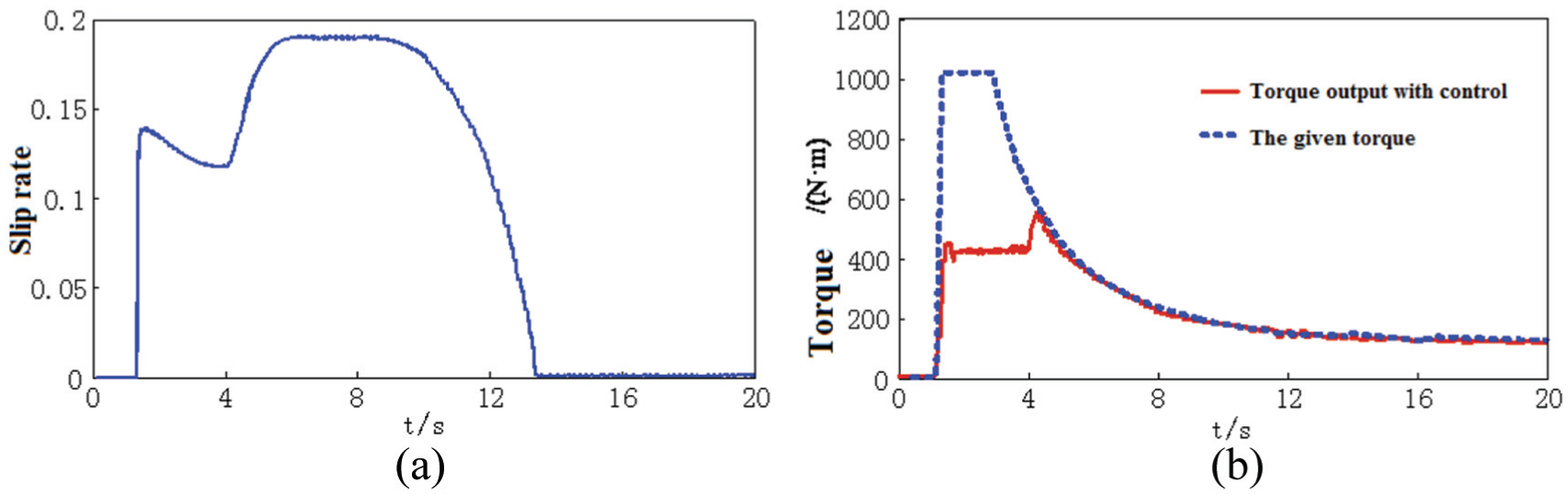
The result of simulation of driving on different adhesion coefficient road: (a) the slip rate of the wheel of first axle on the left with control and (b) the motor torque output of the first axle on the left.
It can be shown in Figure 11(a) that when running on the low adhesion road, anti-skid controller regards 0.12 as optimal control target to adjust the torque of drive motor. When running onto the high adhesion road after 4 s, anti-skid controller detects the change of road surface and reestimates the optimal slip ratio to 0.185. Before the forth second, the anti-skid controller adjusts the motor torque as shown in Figure 11(b), while after the fourth second, the motor control output torque rises obviously due to the better road condition. The motor control output torque reached the gas pedal corresponding torque value, so it outputs the value according to the maximum value of the motor external characteristic.
3. Simulation of running on rise and fall road
This experiment chooses the road that continues to rise and fall, and the road adhesion coefficient is set to
Sometimes in the extreme worst cases, some wheels can even separate from the road. The vertical load changes caused by the rise and fall road surface can affect the performance of the vehicle, which can be equivalent to the vehicles driving on the road of adhesion coefficient which changes continuously. When the wheel contact with the ground is the best, it can be equivalent to high adherent surface road. When the wheel contact with the ground is the worst, or even separated, it can be equivalent to the low adhesion road. Therefore, a continuous rolling road surface can be seen as a road condition on continuous change of tire-road friction coefficient. Take the first axle wheel on the left side as the observation object; the simulation results are shown in Figure 12.
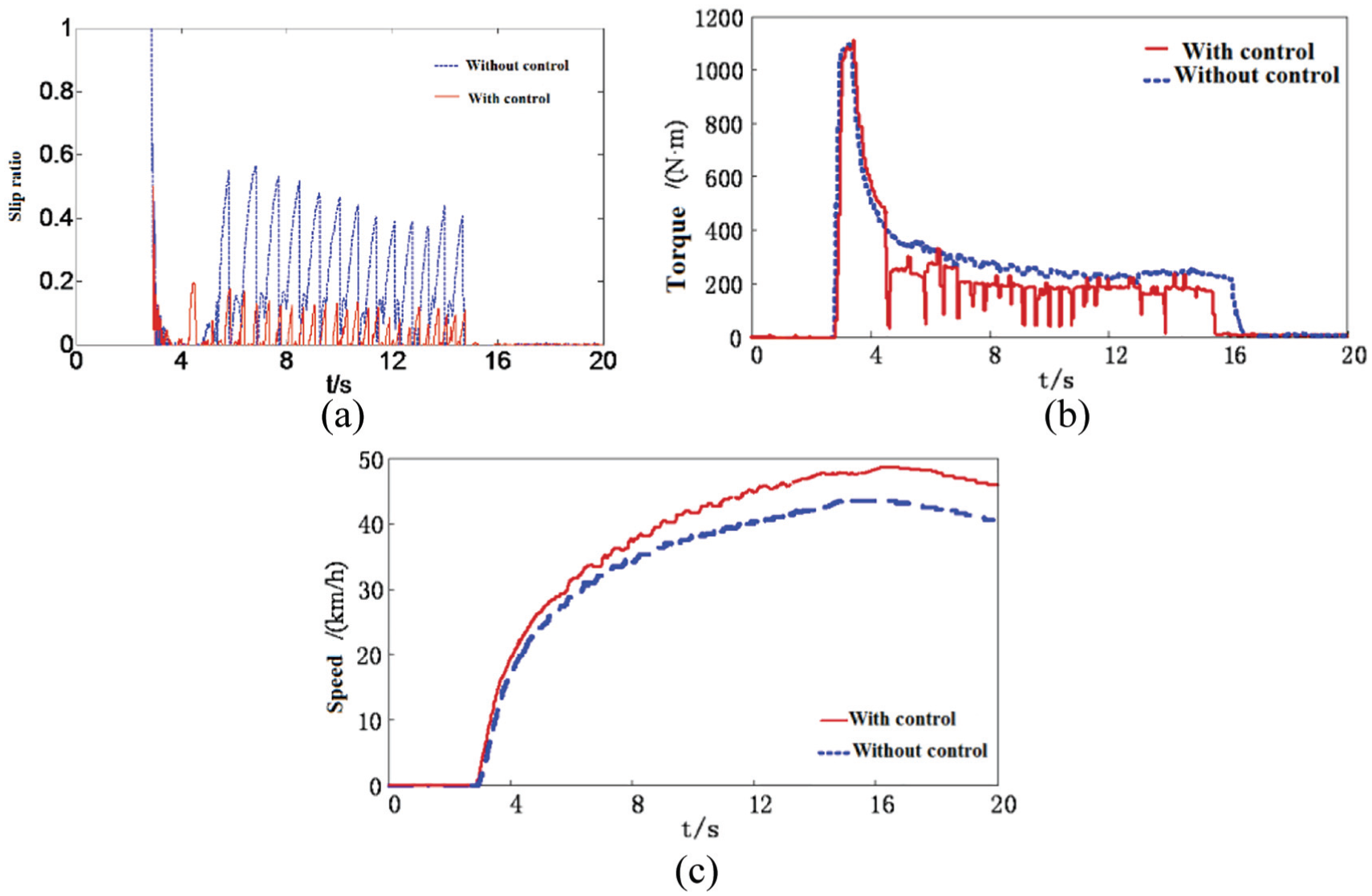
The result of simulation of driving on rise and fall road: (a) slip rate of the first axle wheel on the left, (b) output torque of the first axle wheel on the left, and (c) car speed.
The vehicle begins to enter the continuous rise and fall road at 4.5 s. The optimal slip ratio estimate is between 0.075 and 0.2 in the process of rise and fall road surface. The slip rate is 0.075 when the wheel is separated with road, while it is 0.2 when the contact is close. It can be shown by contrasting the speed simulation result that the anti-skid control improves the speed of vehicles by running in the rise and fall road; furthermore, it improves through performance of vehicle running on barrier road surface.
The joint simulation results of the above three kinds of road surface verified the optimal slip ratio estimation algorithm presented above. The algorithm can effectively achieve the estimation of the optimal wheel slip rate on continuous rise and fall road and single condition road. The anti-skid controller can effectively control the motor torque output, control the wheel slip rate near optimal value, and therefore improve the stability of vehicles running on the low adhesion road, acceleration performance, and performance on barrier surface road.
Conclusion
A real-time simulation system of wheel-motor-driven multi-axle vehicle with “driver-integrated controller” in the loop is established based on RT-LAB simulation platform and Vortex simulation platform based on FlexRay bus data fusion. The simulation experiment indicates that the double torque optimization control can effectively adjust torque distribution on both sides by yawing torque to improve vehicle driving performance, and the data fusion based on FlexRay works well. The driven anti-skid control can effectively restrain the idle phenomenon when wheels are at suspended state. The simulation results are accorded with the expected control goal.
This practice indicates that it is faster and more effective to verify the proposed algorithm and strategy of the integrated control by HIL simulation. It has certain application value and lays the foundation to the code development and control strategy optimization of the wheel-motor-driven vehicle.
Footnotes
Acknowledgements
The authors would like to thank the editor and anonymous reviewers for their helpful comments and suggestions in improving the quality of this paper.
Handling Editor: Daming Zhou
Declaration of conflicting interests
The author(s) declared no potential conflicts of interest with respect to the research, authorship, and/or publication of this article.
Funding
The author(s) received no financial support for the research, authorship, and/or publication of this article.