
Abstract
The effects of curvature ratios on heat transfer and flow characteristics based on multi-sensor technique for the multi-layer winding hoses are studied. A multi-sensor–based experimental platform is established. The working fluid is oil and the multi-layer winding hoses are produced by winding a 13.00 mm diameter hydraulic hose on a reel from 1 to 12 turns. Experiments on different curvature ratios for the multi-layer winding hose with constant wall temperature are presented. Ak–ε standard model has been applied to present the simulations on heat transfer and turbulent flow. In order to solve this model, a finite volume method has been used. The simulation results are compared with the experimental results. The simulation results and experimental results are in the similar varying trends. The effects of centrifugal force in the multi-layer winding hose on heat transfer and pressure drop have been discussed.
Introduction
With the development of diaphragm wall construction, deep water salvage, oil exploitation, and so on, the length of hydraulic pipes utilized in these fields need to be longer and with larger curvature ratios. The multi-layer winding hose (which is also known as MLWH) with compact structure which meets the engineering demands well is getting more and more attentions.
Compared with straight pipes, the problems of turbulent flow and heat transfer in multi-layer winding pipes are much more complex. The reason for this is mainly about the secondary flow which is caused by centrifugal force in curved pipes. 1 The curved pipes have wide applications in engineering systems due to its special structure and heat transfer characteristics. 2 The curved pipes can be divided into three groups: helically coiled pipes, spirally coiled pipes, and other curved pipes.2–4 The MLWH studied in this article can be classified into spirally coiled pipes according to the definitions of curved pipes. Helically and spirally coiled pipes are well-known types of curved pipes used in a great diversity of applications. 5 Nonetheless, majority of the relevant studies for curved pipes are paying close attentions to the helically coiled type.
Early studies6,7 were focused on the problems of flow characteristics and heat transfer in helical coils. Recent studies trend to investigate problems of pressure drop and heat transfer in helical coils by numerical simulations and experiments. Piazza and Ciofalo 8 studied turbulent flow and heat transfer in helically coiled pipes and proposed a numerical prediction which were compared to pressure drop and heat transfer data in the literature. Kharat et al. 9 presented a correlation between gap, tube diameter, and coil diameter of the concentric helical coils while computational fluid dynamics (CFD) simulations and experimental results were also presented to make comparisons. Wu et al. 10 investigated that the Reynolds number, curvature ratio, and coil pitch had influence on the helically coiled pipes with uniform wall temperature. Zhang et al. 11 presented a numerical simulation on spherical corrugation to investigate the heat transfer and pressure drop problems in helical coils. Cioncolini and Santini 12 carried out an experiment to study the flow transition in helically coiled pipes. Naphon 13 proposed an experiment to study the thermal problems and the pressure drop in the helically coiled heat exchangers. Cui et al. 14 presented experiments for refrigerant R134a to obtain the effects of flow characteristics and pressure drop. Pawar and Sunnapwar 15 presented experiments using Newtonian and non-Newtonian fluids to study the heat transfer problems under isothermal and non-isothermal conditions in helical coils. Amicis et al. 16 presented experimental and numerical works in helically coiled pipes to investigate the friction factor and flow transition problems of steady incompressible laminar flow.
Compared to the numerous researches in helically coiled type, there are few studies in spirally coiled pipes in available literature. Ali and Seshadri 17 presented a study of pressure drop in isothermal, steady Newtonian flow in an Archimedean spirally coiled pipe. Naphon and Suwagrai 1 proposed an experiment to investigate the curvature ratios effects on the heat transfer and flow characteristics in a horizontal spirally coiled pipe. Yoo et al. 18 performed numerical simulations in spirally coiled pipes to investigate flow and thermal field characteristics. Sasmito et al. 19 presented a numerical method to study the heat transfer problems of in-plane spirally coiled pipes with different cross sections like rectangular, square, triangular, trapezoidal, circular, and half circular. Altaç and Altun 20 investigated a numerical method in spirally coiled pipes to study the flow development and heat transfer problems with steady state. Reddy et al. 21 presented a heat exchanger with helical coils and performed a CFD analysis. Kharvani et al. 22 proposed an active method using a rotating ball valve as a pulse generator to increase the heat transfer rate in a spirally coiled pipe. Ji et al. 23 studied the flow and heat transfer performances of horizontal spirally coiled pipes of circular and elliptical cross sections.
The curved pipes mentioned above are all about the heat transfer and flow characteristics in heating/refrigeration systems, chemical production systems, and heat exchange systems. No literature has ever mentioned the heat and flow characteristics for MLWH which is widely utilized in engineering machinery. This work is to investigate the heat transfer and flow performances of the MLWH numerically and experimentally. The research can help the study of the mechanism of the heat transfer and flow characteristics for multi-layer wind hose, the optimization of the pipe structure, and improvement of the engineering machinery.
Inspired by the idea of Zhou and colleagues,24,25 the contributions in this article are summarized as follows:
A hydraulic testing platform, which is based on the large-scaled and long-distance engineering apparatus, with the MLWHs is presented.
The mathematical model of the MLWH system is proposed. Five MLWH systems with different configurations are tested based on the proposed experimental scheme. The experimental data for pressure, temperature, and flow rate are obtained.
Simulations on different configurations of the MLWH systems are presented. The calculated data based on simulations are obtained.
To demonstrate the validity of the MLWH system and verify the characteristics of flow performances and heat transfer, the comparisons between the experimental results and computational results for working oil temperature, output oil temperature, Nusselt number, heat transfer rate are presented.
Experimental instruments and procedure
A principle diagram of the experimental instruments has been shown in Figure 1(a). The experimental instruments are composed of a test section, sensor groups, data collection system, and a reel. The test section is composed of the MLWH and a reel. The dimension parameters of the test section are listed in Table 1. There is also a symmetric MLWH installed on the reel to establish the oil circuit in Figure 2(a). The sensor group is divided into inlet sensor group and outlet sensor group, which are shown in Figure 2(b) and (c). The inlet sensor group is set at the outlet of the pump and set to measure the pressure and oil temperature value at the outlet of the pump. The inlet sensor group consists of a temperature sensor and a pressure sensor. The outlet sensor group is set at the end of the test section to measure the pressure, oil temperature, and flow rate value of the test section and is composed of a temperature sensor, a pressure sensor, and a turbine volume flow senor.

(a) Principle diagram of the experimental instruments and (b) principle diagram of pump station.
Dimension parameters of the MLWH.

MLWH: multi-layer winding hose.

Experimental setup of the MLWH system: (a) experimental platform of the MLWH system, (b) inlet sensor group of the present system, (c) outlet sensor group of the present system, and (d) data collection system.
The working oil is stored in a tank. A variable capacity pump controlled by a motor is applied to pump the working oil out of the tank. The working oil is passed through the inlet sensor group which is composed of an inlet temperature sensor and an inlet pressure sensor. After passing through the inlet section of the MLWH system, the oil flows through a swivel joint and enters to the test section. After being transmitted thought the test section, the working oil passes through the outlet sensor group which combined with a pressure sensor, a flow sensor, and a temperature sensor. After flowing through the main experimental section of the MLWH system, the oil is passed through a proportional relief valve which is set to protect the hydraulic system and provide loads in some special occasions. After passing through the proportional relief valve, the working oil passes through a MLWH which is symmetric to the test section, another swivel joint, and finally returned to the tank. The flow rate adjustment for the MLWH system is realized by controlling the variable capacity pump to change the pumping flow rate of the working oil. The flow sensor set at the outlet section is utilized to realize the flow rate adjustment of the whole system.
In order to measure the pressure drop under different configurations of the MLWH system, two pressure sensors with accuracy of ± 0.3% are employed at the inlet and outlet sensor groups. The inlet temperature and outlet temperature of the working oil are measured by two temperature sensors with accuracy of ±0.2%. A flow sensor with the accuracy of ±0.2% is employed to measure the flow rate of the system.
Experiments are carried out by controlling the entry oil flow rate of the test section with various number of coil turns. The number of coil turns is adjusted using a pump station (Figure 1(b)) to achieve the desired experimental conditions. Experiments are conducted at five different winding layers in this study. In order to obtain stable data, the MLWH system is allowed to recording the signal from the measurement instruments after steady-state condition by the data collection system. Data collection is presented by utilizing a data collection system which all data are recorded as shown in Figure 2(d). The data collection system is composed of a controller, a display screen, and a PC. During the experiment, the experimental data from the sensors mentioned in Figure 2(b) and (c) are collected and sent to the controller. The controller processes the data input and makes the relevant actions to the whole MLWH system. The display screen is used to help the observation of the experimental data. Also, the display screen is connected with the controller by controlled area network (CAN) bus. The data collected and processed are transmitted to the database in PC. The experimental conditions of sensors are given in Table 2.
Sensor conditions of the experiment.

Mathematical model and configurations of the MLWH
Figure 3(a) shows the geometric structure of the MLWH where

Mathematical model and configurations of MLWH: (a) structure of MLWH, (b) 1 layer, (c) 3 layers, (d) 6 layers, (e) 9 layers, and (f) 12 layers.
With variation of the outmost radius
Numerical analysis
In order to analyze the heat transfer and flow characteristics in the MLWH, numerical simulations are proposed to for the oil at different geometrical parameters under the same working conditions. Three-dimensional (3D) models are produced by SolidWorks; meanwhile, the unstructured nonuniform girds are employed to mesh the 3D models. In order to get higher accuracy in the results, higher quality grids are utilized at the boundaries between oil and internal wall of the MLWH, which has been shown in Figure 4.

Grid system for MLWH.
Tests on grid independence have been proposed by different grid distributions of
According to the mathematical model part, the following assumptions should be considered: The model calculation region is 3D; the working fluid (oil) is incompressible; the natural, radiation factors are neglected; the viscosity factors are ignored.
The governing equations of the fluids can be expressed as follows:
Community equation

where matrix V denotes the velocities in axial, radius, and azimuthal directions. And the matrix V can be written as
Momentum equation
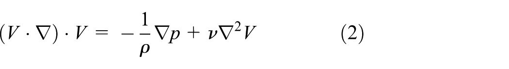
where p denotes the pressure term.
Energy equation

where T represents the temperature term.
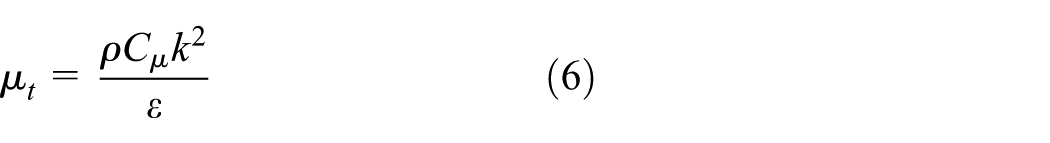
Considering the geometry and physical problems of the MLWH, the turbulent flow and heat transfer performance are simulated by the

where k denotes turbulent kinetic energy;
The turbulent kinetic energy dissipation equation is expressed as
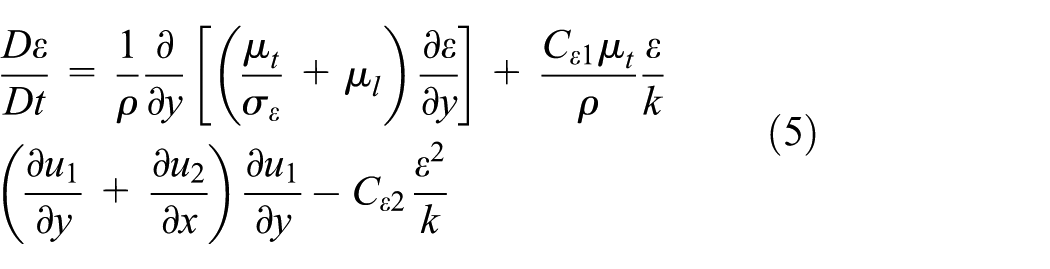
where
The turbulent kinetic energy k and the turbulent kinetic energy dissipation
The empirical constants obtained from the numerous data fitting for the turbulent flow by previous studies1,27,28 are
The boundary conditions of the MLWH wall are defined as no slip and isothermal boundary conditions which is shown as follows

The inlet boundary conditions are as follows

The inlet turbulent kinetic energy
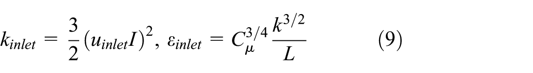
The intensity of the turbulent I is defined as follows

where
The following variables and parameters are proposed to describe the results and specialties on heat transfer and flow characteristics in the MLWH

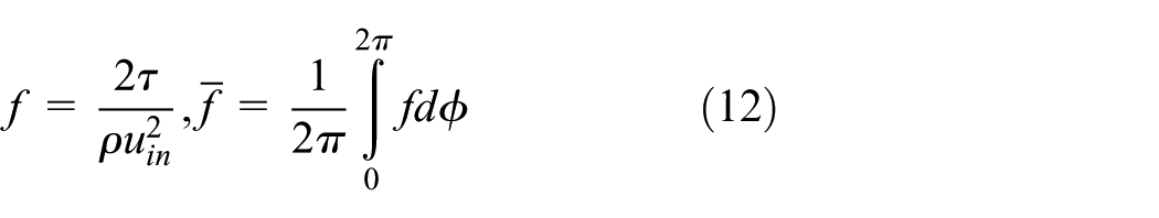

where
According to equations (1)–(10), the velocity and pressure term are coupled to the governing equations. For purpose of solving the coupling problems of velocity and pressure term, the governing equations and the boundary conditions of the 3D models are handled by semi-implicit method for pressure linked equation consistent (SIMPLEC) algorithm which is based on control volume method and presented by Van Doormaal and Raithby.29–31 Also, the second-order upwind scheme is utilized to discretize the governing equations. The numerical solvers set in the commercial software FLUENT is utilized. The criterion for ending the numerical computations satisfies the following equation
where
Results and discussions
There is almost no data for the heat transfer and flow characteristics of the MLWH in open publications. The numerical calculated results and the presented experimental data are compared in this article. Figure 5 shows the oil temperature variations with different winding layers for different oil mass flow rates experimentally and numerically. The oil pumped from the tank entering the inlet layer flows along the MLWH and flows out at the outlet layer. The experiments are presented under constant hose wall temperature for the 1st, 3rd, 6th, 9th, and 12th winding layers. The inlet oil temperature is
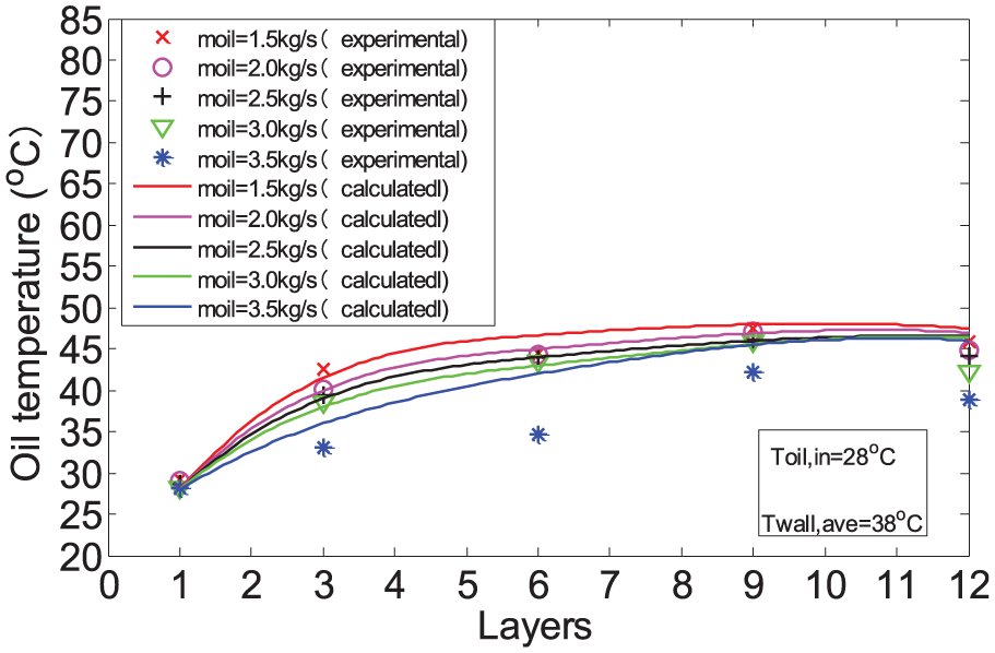
Oil temperature with different winding layers.
As shown in Figure 5, the mass flow rate of MLWH presented in the current study is 1.5, 2.0, 2.5, 3.0, and 3.5 kg/s. In order to study the oil temperature effect for the MLWH, the oil temperatures are evaluated to the number of winding layers. It is demonstrated that the oil temperature increases with the augment of winding layer numbers and the temperature effect tends to decrease at higher layer numbers. It is noticeable that with the increasing of the oil mass flow rate with the constant inlet and average hose wall temperatures, the oil temperatures of different layer numbers decrease. Figure 5 also shows the comparison between the present experimental results and the calculation results. It is clear that the results from the experiment are smaller than the calculation one. There are some assumptions and simplifications in the process of calculated results calculation; meanwhile, the actual experimental conditions are much more complex.
As shown in Figure 6, the outlet oil temperatures are evaluated against the oil mass flow rate with different curvature ratios. It is noted that the outlet temperature reduces with the increasing oil mass flow rate when the inlet oil temperature and average wall temperatures are constant. It is clear that with a prescribed oil mass flow rate the oil temperatures will be higher at lower curvature ratios. The main cause of this is mainly about the hose length. The hose length with lower curvature ratios is much longer than that with higher curvature ratios. Comparing the experimental data to the calculated data, it is obvious that the calculated outlet oil temperature is much higher than the experimental one.

Outlet oil temperature with different oil mass flow rates.
The heat transfer rate varies with the oil mass flow rate which has been depicted in Figure 7. It can be pronounced that the heat transfer rate augments at higher oil mass flow rate. It is clear that the curvature ratios do have effects on the heat transfer rate. For the calculated results, the augmentation of heat transfer rate is proportional with the augment of the oil mass flow rate. For the experimental results, the augmentation of heat transfer rate also be proportional with the oil mass flow rate augmentation, but with a gentler gradient. The comparison between the calculated data and experimental data is in agreements with the variation trends while the values of the calculated results are larger than that of the experimental results. The viscosity of the working fluid and the elasticity of the hose have not been considered during the calculation which led to the difference between the calculated data and experimental data.
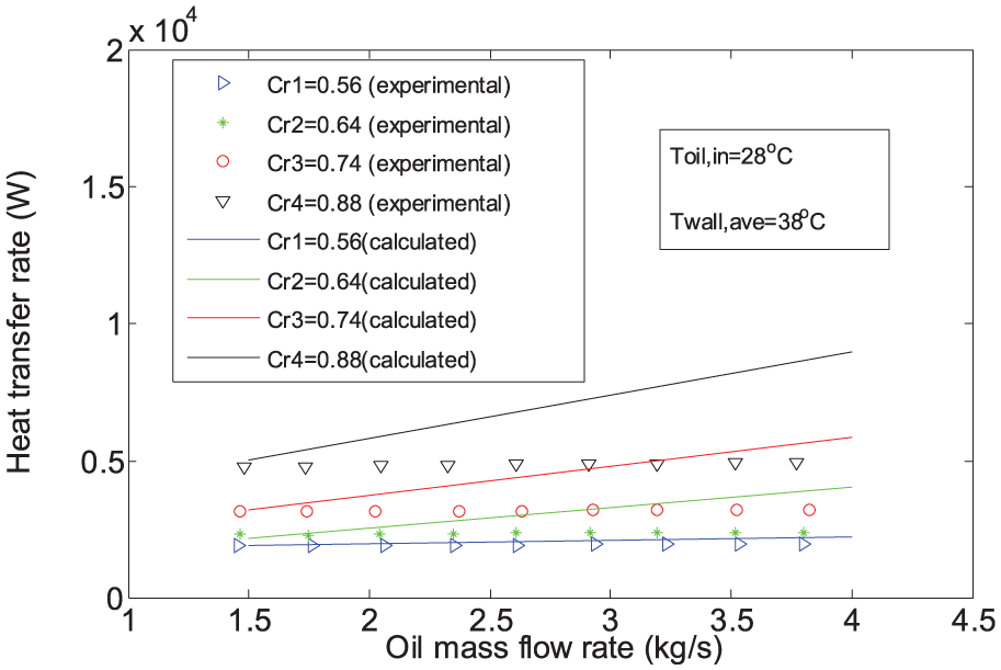
Heat transfer rate with different oil mass flow rates.
The average Nusselt number variations which are obtained from the experimental data with oil mass flow rate with different curvature ratios are depicted in Figure 8. It can be pronounced that most of the average Nusselt numbers obtained from experimental data, which depends on the removal capacity to the heat of working oil, increase with augments of the oil mass flow rate. Considering the average Nusselt number calculated from the experimental data, it is higher with lower curvature ratios than that of the higher curvature ratios in the same oil mass flow rate. But, the experimental data at curvature ratios of 0.64 and 0.74 are quite special. The reason for this is because of the temperature factor which was uneasy to be controlled in the experiment.
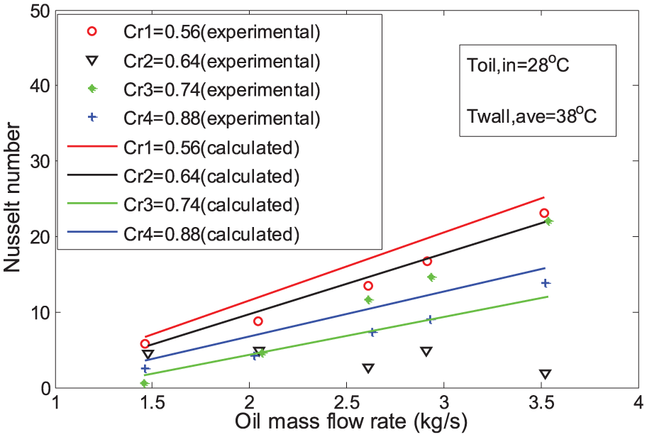
Nusselt number with different oil mass flow rates.
The results of pressure drop per unit length for the MLWH are depicted in Figure 9. It is noticeable that with the pressure drop augmentation, the oil mass flow rate increases correspondingly. Most of the experimental data are in reasonable accordance with the calculated results from the comparisons. Due to the centrifugal force which is the main reason for radius direction velocity, the pressure drop per unit length with lower curvature ratios is much lower than that with higher curvature ratios. Also, it is clear that the pressure drop with the curvature ratio of

Pressure drop per unit length with different oil mass flow rates.
Conclusion
New experimental data under constant hose wall temperature with heat transfer characteristics in MLWH have been presented. The development and distributions problems of heat transfer in MLWH have been described by the numerical calculations. The trends of calculated results and experimental data are in a reasonable agreement. Furthermore, the effect of the secondary flow which is caused by the centrifugal force has been proved to have effects on the heat transfer and flow characteristics of the MLWHs. But, in this work, the viscosity of the working fluid and the elasticity of the MLWH had not been taken into account which had led to inconsistencies of the experimental data and calculated data. Therefore, our future works will focus on the pressure drop, fluid structure interaction, and fatigue problems of the MLWHs, which can help to explain the flow characteristics and hose damage mechanism furtherly.
Footnotes
Handling Editor: Daming Zhou
Declaration of conflicting interests
The author(s) declared no potential conflicts of interest with respect to the research, authorship, and/or publication of this article.
Funding
The author(s) disclosed receipt of the following financial support for the research, authorship, and/or publication of this article: This research is supported by the Fundamental Research Funds for the Central Universities (1000219200), National Natural Science Foundation of China (51605279), and National Key R&D Program of China under Grant 2016YFB1200600.