
Abstract
Estimation and compensation for hull deformation is an indispensable step for the ship to establish a unified space attitude. The existing hull deformation measurement methods are dependent on the pre-established deformation model, and an inaccurate deformation model will reduce the deformation estimation accuracy. To solve this problem, a hull deformation estimation method without deformation model is proposed in this article, which utilizes the neural network to fit the hull deformation. To train the neural network online, connection weights of the neural network are regarded as system state variables which can be estimated by the Unscented Kalman Filter. Simultaneously, considering the time delay problem of inertial data, a time delay compensation method based on the quaternion attitude matrix is proposed. The simulation results show that the proposed method can obtain high estimation accuracy without any deformation model even when the inertial data are asynchronous.
Introduction
Modern large ships are equipped with the high-precision center inertial navigation system (HCINS) which provides a unified attitude reference for shipboard equipment by transfer alignment technology. However, the ship is not an absolutely rigid body, and the hull deformation will seriously affect the performance of transfer alignment. Even if the attitude information of the center inertial navigation system (INS) is relatively high, it will be completely submerged in the error caused by the hull deformation. Therefore, to make full use of the navigation information of the center INS, a unified space attitude reference between the ship borne equipment and the center INS needs to be established, and hull deformation should be measured and compensated in real time.
In the last few years, several approaches have been proposed for addressing this task and remarkable performance has been achieved thanks to inertial measurement matching method (IMMM). The principle diagram of this method for measuring deformation is shown in Figure 1. Two inertial measurement sensors (IMSs) are installed on two different locations of the ship: one near to the HCINS and the other near to a shipboard equipment. If there is a deformation between the two locations, the ship motion sensed by the two IMUs will also be different, and the deformation angle can be estimated by the Kalman filter (KF) based on the information output from two IMUs.

Schematic diagram of the hull deformation measurement based on inertial measurement matching method.
The research on inertial measurement matching includes inertia matching function and hull deformation model. Inertia matching function as the basis of IMMM plays an important role in estimating hull deformation. The angular velocity matching function has been widely applied to deformation measurement since it was put forward.1–8 If the inertial sensors used are accelerometers and gyroscopes, velocity and angular velocity matching function can be established based on the sensor information.9,10 In addition, in order to improve the signal-to-noise ratio of the deformation measurement results, the attitude matching function has been established by choosing attitude as observation, compared with the other two methods; it can obtain higher precision deformation estimation results,11,12 for this reason we use it as the basis of inertia matching method in this article. In terms of hull deformation model, IMMM commonly divides the hull deformation into static deformation and dynamic deformation and models them, respectively. Generally, two different modeling methods are used for static deformation in pertinent literatures. The first method, considering the period of static deformation, is usually long and identifies the static deformation to a constant value.1–7,10 The second method uses a random walk process driven by white noise (WN) to represent the static deformation.8,11 Recently, compared to static deformation, dynamic deformation modeling has received more attention. The second-order Gauss–Markov process is the most commonly adopted to depict the dynamic deformation according to its time characteristics.1–3,6–17 To improve the dynamic deformation model according to the specific working condition and environment, an integrated Gauss–Markov processes model has been proposed 5 instead of the traditional second-order Gauss–Markov process model. Although IMMM with this model can give acceptable results in many applications, it has been recognized that these dynamic deformation model does not consider correlation between three dimensions. This problem can be overcome by a kind of autoregressive exogenous (ARX) model. 4 However, for the complexity of the ship structure and uncertainty of sea wave loads, the accuracy and universality of this model have not been validated. L Joon and L You-Chol 14 pointed out that the Y-axis deformation component was relatively large and had a significant influence on the KF’s performance of azimuth error estimation. Considering difficulties in modeling the deformation phenomena, they excluded the state and measurement variables closely related to Y-axis deformation effects in the transfer alignment process, and their simulation results showed favorable performance of the scheme. The hull deformation affects not only the angular velocity matching method but also the velocity matching method. Due to flexural deformation, lever-arm length is no longer a fixed value but changes with deformation. In order to compensate the dynamic lever-arm effect on information sharing between the main and slave INSs, the model between dynamic lever arm and deformation angle was established by Wang et al. 16 ; at the same time, a matching method was proposed with real-time closed-loop correction of the lever-arm length, compared to the conventional method, and they could effectively estimate misalignment angle and dynamic lever-arm length with disturbance.
Hull deformation estimation is of great significance for inertia matching method to acquire high accurate result. Kalman filtering is the most widely used state estimation method for hull deformation estimation;1–5,10–20 it can solve linear problem with good convergence and the ability to remove high-frequency noises. However, when the inertia matching function is nonlinear, KF is not suitable. With respect to the nonlinear problem of hull deformation measurement, W Gao et al. 7 discussed the effectiveness of two nonlinear filtering algorithms for deformation estimation, and they gave the conclusion that with the augmentation of the model nonlinearity, Unscented Kalman Filter (UKF) is more effective than Extended Kalman Filter (EKF). Besides, Cubature Kalman Filter (CKF) 6 and interacting multiple model (IMM) Kalman filtering 9 are also used to estimate the hull deformation.
To further improve the estimation accuracy of hull deformation, many researchers focus on model parameter estimation. At present, there are mainly two approaches for estimating the parameters of the deformation model. The first is the analytical plus empirical approach, it considers the unknown parameters as functions of the correlation time and the dynamic deformation signal’s variance. The second is the statistical approach; it determines the model parameters according to the previous dynamic deformation measurement data,18–20 typically by the least squares method. Besides, the literature2,3 introduced the Tufts-Kumaresan method to compute the hull deformation parameters in real time, and the simulation results showed that the method can estimate the dynamic deformation parameters with a high degree of accuracy. These parametric estimation methods are based on the assumption that the deformation model is fixed; however, the hull deformation model varies during the actual navigation process. It should be noted that the time-varying hull deformation model could not be accurately modeled, which causes a larger hull deformation estimation error.
Inspired by these works, a model-free hull deformation measurement method based on attitude matching is proposed. In this article, the total deformation is fitted by a neural network; in this way, we do not need to establish the static and dynamic deformation models, so the deformation estimation accuracy is immune to the changes of model and parameters, but now two new problems have arisen: (1) how to train the neural network online without any prior deformation data, but can ensure the accuracy and real-time requirements of hull deformation estimation in the complex sea condition and (2) how to combine the neural network and inertia matching method. Fortunately, there are several literatures that can enlighten us; Kramer et al.21,22 corrected the target registration error by the neural EKF method; they used a neural network to approximate the error function of the priori sensor dynamic model and then trained the neural network by EKF. Based on the ideas of these papers, we treat the network weights as the state of the nonlinear system and then estimate the system state by a nonlinear KF.
In the actual voyage, there inevitably exits a time delay in the data transmission between the two IMSs. The time delay can lead to the mismatch of inertia data, which will bring large deformation estimation errors. To solve this problem, a time delay compensation method based on quaternion attitude is proposed; this method is different from the existing method which is based on direction cosine matrix, 14 and it has more concise mathematical derivation and faster convergence ability. In this article, a time delay variable is introduced, the mathematical relationship between the ideal and actual attitude matrix is deduced based on the quaternion attitude matrix, and then a model-free inertia matching method with time delay compensation is presented.
In summary, we make the following contributions:
We propose a hull deformation measurement method based on attitude matrix matching, which utilizes a neural network to fit the deformation angle. To train the neural network online, a nonlinear KF is applied to estimating the network weights.
A time delay compensation method based on quaternion attitude matrix is proposed. We extend the delay time to the system state model and estimate it by the KF.
To verify the effectiveness of model-free and time delay compensation of our method, two kinds of simulation experiments are conducted. The traditional deformation measurement method based on priori model is selected as the contrast algorithm.
This article is organized as follows. Section “Inertia matching function and gyro drift model” describes the attitude matching function, inertial space misalignment angle, and gyro drift model. Section “Time delay compensation and model-free deformation measurement” presents a time delay compensation and model-free method based on attitude matching function and gives the system filtering equation. Section “Experimental results and analysis” evaluates our method in the simulation experiments. Section “Conclusion” concludes this article and provides future work direction.
Inertia matching function and gyro drift model
Attitude matching function
The IMMM based on KF commonly includes angular velocity matching method, velocity plus angular velocity matching method and attitude matching method. 11 Based on the hull deformation measurement method described by Zheng et al., 11 an attitude matching function is built.
As illustrated in Figure 1, supposing that the inertia sensors are two ring laser gyro units (LGUs), the LGUs are two sets of three mutually orthogonal gyros, LGU1 and LGU2, which are installed on the hull center and bow, respectively. The LGU1 coordinates are ox1y1z1, the x-axis ox1 is along the starboard side of the hull, the y-axis oy1 is parallel to the longitudinal axis of the hull, and the z-axis oz1 is perpendicular to the deck. The LGU1 coordinates ox1y1z1 have been aligned with the carrier coordinates b1. The LGU2 coordinates ox2y2z2 are defined as the coordinates ox1y1z1, and they are in accordance with the carrier coordinates b2. The total misalignment Euler angle between the coordinates ox1y1z1 and the coordinates ox2y2z2 is
Considering the definition of frames, the relationship among rotation matrices can be described as follows

where

Let
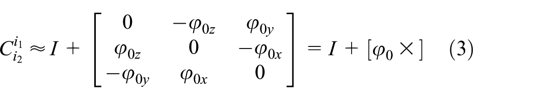
Let
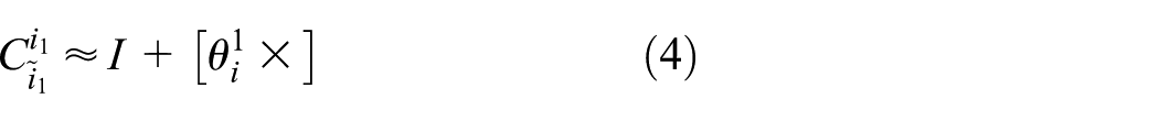
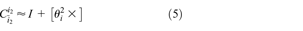
From formulas (1)–(5), we have

Omitting the second-order small quantities, we have

Let

By inserting

Let
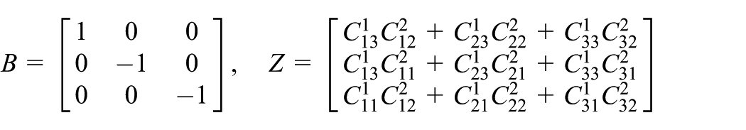

Then formula (9) can be described by

Inertial space misalignment angle
With the update of the attitude, the calculation inertial frames

where
Gyro drift model
Laser gyro constant drift and random drift models can be described as follows
LGU1 constant drift:
LGU1 random drift:
LGU2 constant drift:
LGU2 random drift:
where
Time delay compensation and model-free deformation measurement
Time delay compensation
In the practical application environment, the data transmission of LGU1 and LGU2 is not synchronized; if we use the asynchronous data to estimate the hull deformation, the estimation accuracy will decrease severely. We assume that there is no time delay for the data of LGU1, but the data of LGU2 have a time delay Δt, besides, the quaternion algorithm is used for attitude update, then the relationship can be obtained by Taylor expanding the ideal attitude matrix

where
where

where T is the sampling time,
By inserting equation (12) into equation (7), we get
Selecting the elements (1, 2), (3, 1), and (3, 2) from matrixes on the left and right sides of the equal sign, we get

where
Supposing that Δt is a small amount, neglecting the second-order small quantity

Establishing the system observation equation with neural network
Considering the system model, the system state vector is selected as follows

By introducing the system state vector, formula (16) can be written as follows

where
Establishing the system state equation
Because the initial deformation angle

Considering the time delay as a constant, we have

According to the inertial space misalignment angle, gyro drift models, (18) and (19), we can get the following

The above state equations can be presented in a standard matrix form as follows

The system state variables X and the neural network connection weights W are combined to form new state variables

where

Structure of the typical multilayer neural network.
Discretizing the state equations (21), we have

The state equations with augmented state variables can be given as follows

where

Optimal state estimation by nonlinear filter and deformation estimation
Considering the system state equation and observation equation, the system filtering equation can be written as follows
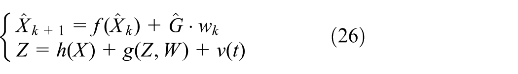
Since the neural network contains nonlinear activation functions, it is also nonlinear, that is, the observation equation is nonlinear, a nonlinear filtering is commonly used for time update and measurement update;21,22 here, we select the UKF to estimate the system optimal state.
When the system optimal state is obtained, that is, the weight W of the neural network is obtained, and then the output
Experimental results and analysis
Two kinds of semi-physical simulation experiments are conducted to examine the characteristics of model-free and time delay compensation of the proposed method.
Simulation conditions
Figure 3 shows a diagram of the LGU1 data and LGU2 data simulation process. The LGU1 data are generated by adding the static data of the ring laser gyro INS shown in Figure 4 to the ship motion simulation data, then it is transformed into the LGU2’s frame by the direction cosine matrix which is calculated by the deformation angle, based on these data, together with deformation angle velocity, the LGU2 data can be simulated.

Schematic diagram of LGU data simulation and hull deformation estimation.

The ring laser gyro inertial navigation system.
Figure 4 is the outline drawing of a high-precision Mechanically Dithered Ring Laser Gyroscopes Inertial Navigation System; the system consists of an inertial measurement unit, a navigation computer, and a secondary electric power supply. The inertial measurement unit consists of three-axis gyro components and accelerometer modules. The inertial measurement unit is composed of a triaxial orthogonal gyro component and an accelerometer component. As shown in Table 1, the constant bias of the gyro on each axis is 0.005 , the random walk is
Parameters of the gyro and accelerometers noises of the INS.

INS: inertial navigation system.
Without loss of generality, we consider the sinusoidal motion of a ship on the three axes, and the motion model are as follows 16

where
The hull deformation contains static deformation and dynamic deformation. The static deformation is set as constants and the dynamic deformation is set as the second-order Markov process 17 on the three axes

where
Experimental scheme
The proposed method is called Method B. Method A is the traditional hull deformation measurement method with the same matching model and nonlinear filter as Method B, but it needs to establish a priori dynamic and static model for the deformation angle; besides, Method A is not able to compensate the time delay. Method C is same as Method B but without time delay compensation:
The first kind of experiments without time delay is conducted to validate the effectiveness of Method B which does not depend on the priori deformation model. We select Method A as the contrasting algorithm. The sample frequency is 100 Hz, and the total data length is 60 min. Three experiments are conducted as follows: 1.1. Experiment with the accurate priori deformation model
This experiment discusses the comparison between Method A and Method B using the accurate priori model. The static deformation angle is simulated as the constant
1.2. Experiment with an inaccurate priori dynamic deformation model.
In this experiment, we only consider the dynamic deformation model, that is, the static deformation angle is constant 0. The actual dynamic deformation angle is simulated by formula (27), and the formula parameters such as the irregularity coefficients
1.3. Experiment with the inaccurate priori dynamic and static deformation models.
In this experiment, we take into account the inaccuracy of both the dynamic and static models. The dynamic models used in the simulation environment and Method A are all same as that in the experiment 1.2.
The static deformation angle is simulated by the following formula

where
However, Method A models the static deformation as a constant, that is

Based on the above experimental setup, Method A has the inaccurate priori dynamic and static deformation models.
2. The second kind of experiments with time delay are conducted to validate the effectiveness of time delay compensation for Method B. In this kind of experiments, the deformation angle simulation is same as that in experiment 1.3. We select Method C as the contrasting algorithm. The sampling frequency is 200 Hz, and the total data length is 15 min.
There are three experiments conducted as follows:
2.1. The time delay is 10 ms.
2.2. The time delay is 20 ms.
2.3. The time delay is 30 ms.
Parameters of dynamic deformation model used in the LGU data simulation and in Method A.

LGU: laser gyro unit.
Parameters of dynamic deformation model used in the LGU data simulation.

where
Parameters of dynamic deformation model used by Method A.

Experimental results
The first kind of experiments
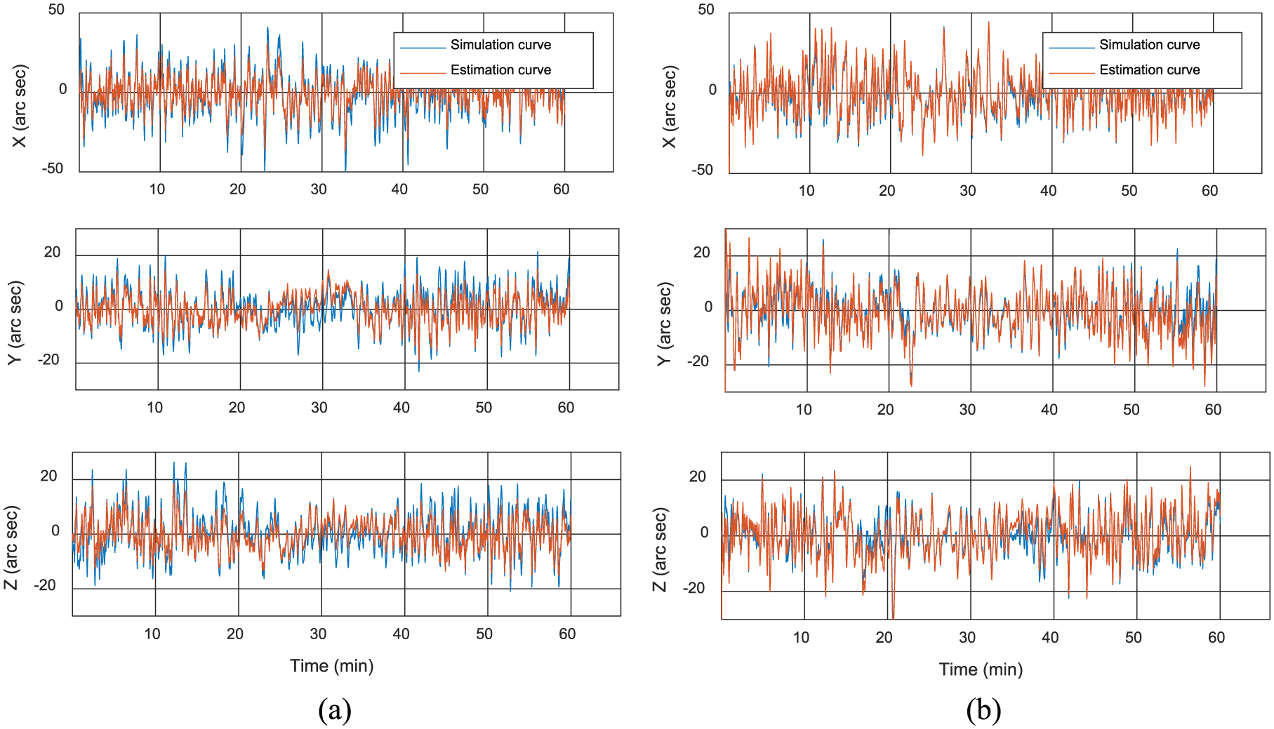
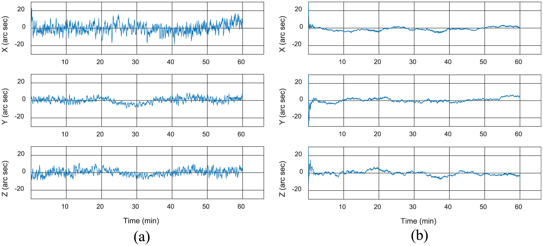
In this experiment, the deformation models are fixed during the simulation experiment and Method A has the accurate priori models. Methods A and B are applied to estimate the deformation angles, respectively. Figure 5 shows comparisons for estimation result and simulation data, and Figure 6 shows the deformation estimation errors on the three axes by two methods. After the estimation errors curve converges, the root mean square errors (RMSE) of the deformation measurement of Methods A and B on the X, Y, and Z axes are as shown in Figure 7.
In this experiment, the dynamic deformation model is varying and Method A has an inaccurate dynamic deformation model; we utilize Method A and Method B to estimate the deformation angles, respectively. Figure 8 shows comparisons for estimation result and simulation data, and Figure 9 shows the deformation estimation errors on the three axes by two methods. After the estimation errors curve converges, the RMSE of the deformation measurement of Methods A and B on the X, Y, and Z axes are as shown in Figure 10.
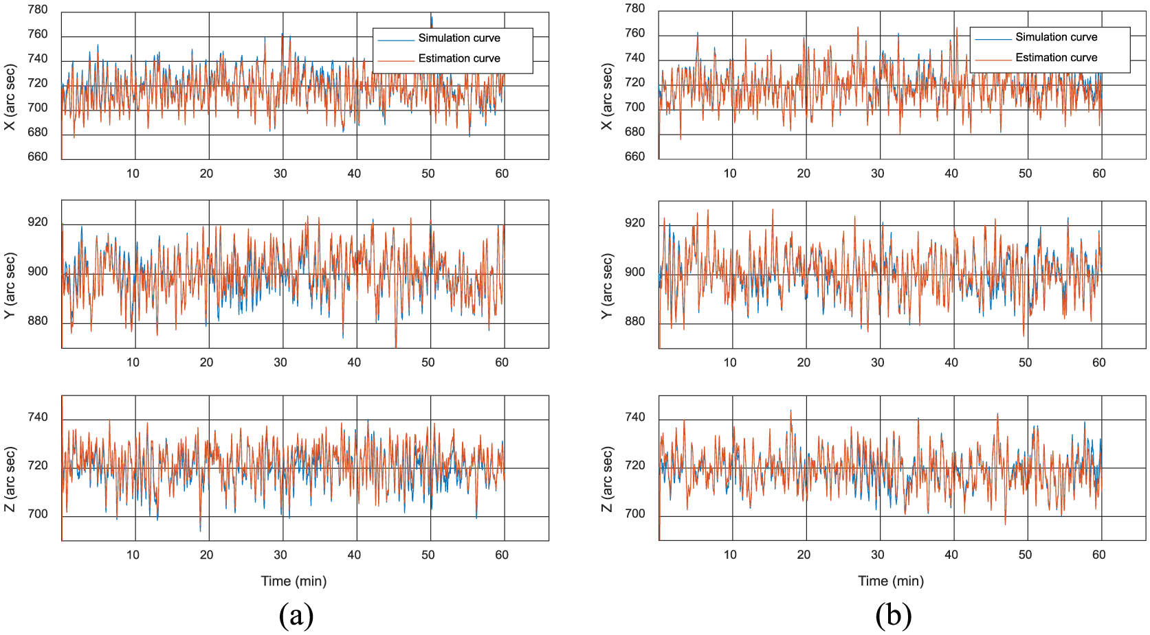
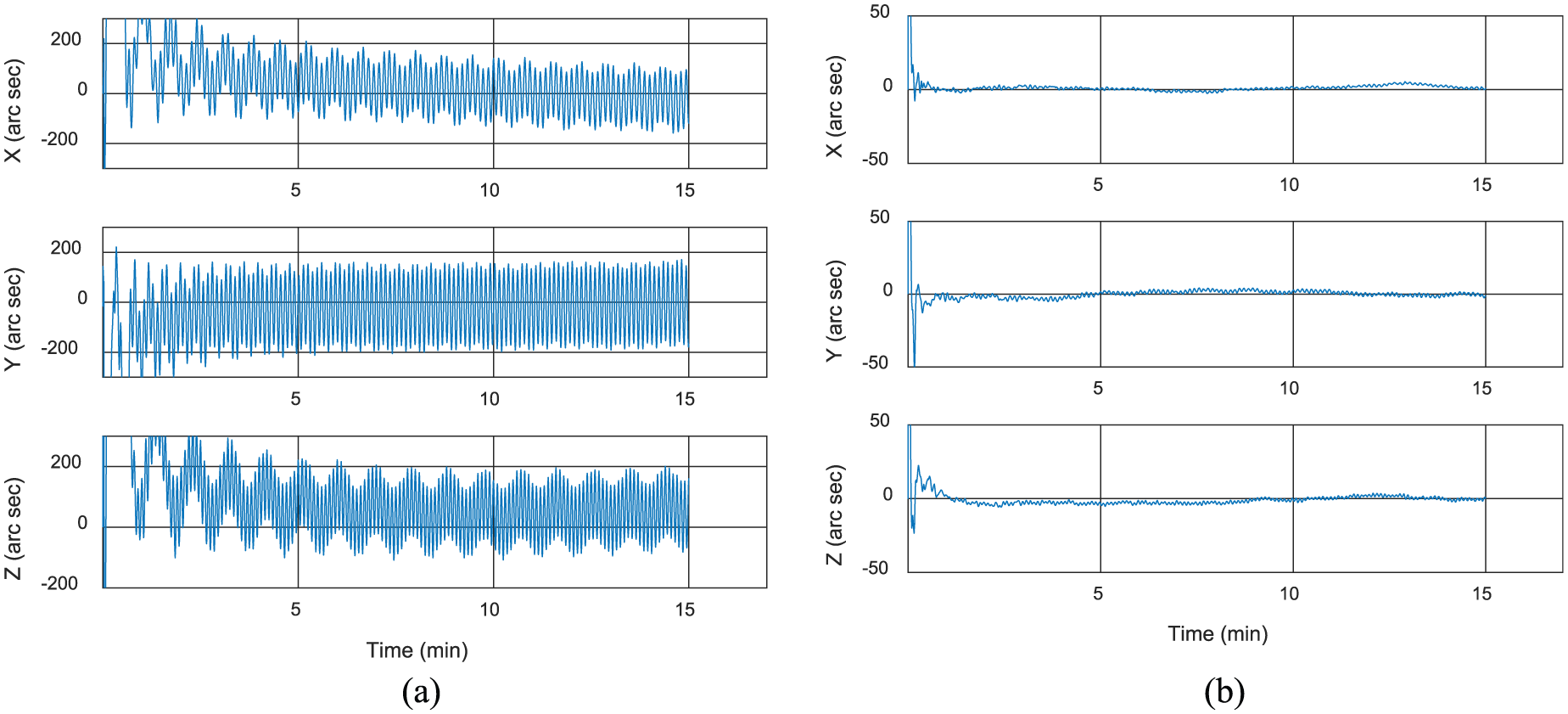
In this experiment, the dynamic and static deformation models are varying during the simulation, and Methods A and B are used to estimate the deformation angles. Figure 11 shows comparisons for estimation result and simulation data, and Figure 12 shows the deformation estimation error results on the three axes by two methods. After the estimation errors curve converges, RMSE of the deformation measurement of Methods A and B on the X, Y, and Z axes are as shown in Figure 13.
Comparison of simulation data and estimation result on the three axes with accurate models by (a) Method A and (b) Method B.

Hull deformation estimation error with accurate models by (a) Method A and (b) Method B.

The RMSE of hull deformation estimation with accurate models.
Comparison of simulation data and estimation result on the three axes with varying dynamic model by (a) Method A and (b) Method B.
Hull deformation estimation error with varying dynamic model by (a) Method A and (b) Method B.

The RMSE of hull deformation estimation with varying dynamic model.

Comparison of simulation data and estimation result on the three axes with varying model by (a) Method A and (b) Method B.

Hull deformation estimation error with varying model by (a) Method A and (b) Method B.

The RMSE of hull deformation estimation with varying model.
The second kind of experiments
In this kind of experiments, the time delays are set as 10, 20, and 30 ms for three experiments, respectively:
When the time delay is 10 ms, the deformation estimation errors on the three axes are as shown in Figure 14.
When the time delay is 20 ms, the deformation estimation errors on the three axes are as shown in Figure 15.
When the time delay is 30 ms, the deformation estimation errors on the three axes are as shown in Figure 16.
All the time delay estimation results are shown in Figure 17.
Hull deformation estimation error for 0.01 s time delay: (a) without delay compensation by Method C and (b) with delay compensation by Method B.

Hull deformation estimation error for 0.02 s time delay without delay compensation by (a) Method C and (b) Method B.

Hull deformation estimation error for 0.03 s time delay: (a) without delay compensation by Method C and (b) with delay compensation by Method B.
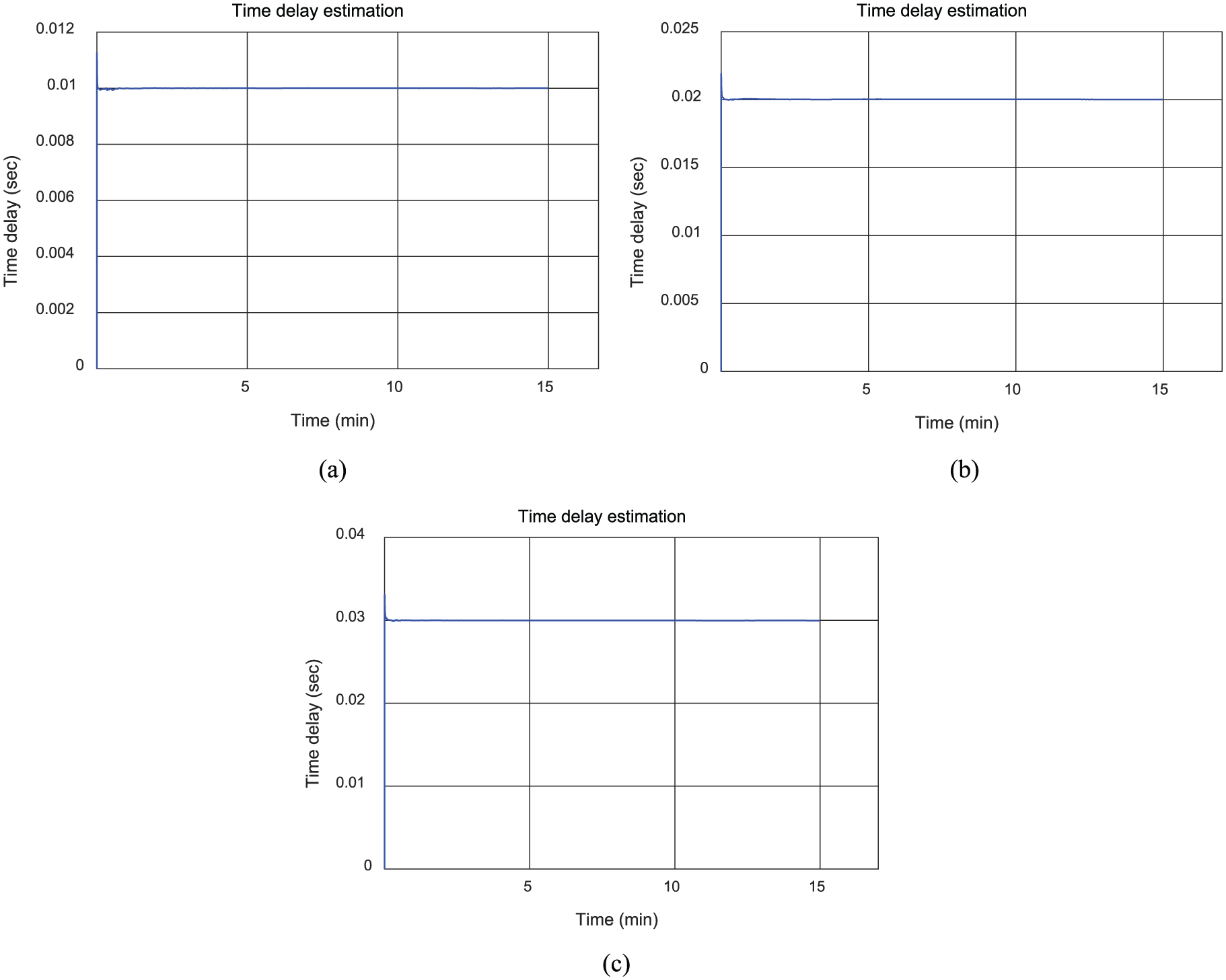
Estimation of the time delay by Method B: (a) 0.01 s, (b) 0.02 s, and (c) 0.03 s.
Experimental analysis
In the first kind of experiments, when the deformation models are fixed and Method A has the accurate priori models, as shown in Figures 5–7, both Methods A and B can effectively estimate the total hull deformation angle. The long-term measurement errors of the two methods on X, Y, and Z axes are less than 10 arc seconds. The RMSE of deformation estimation of Method A on the three axes are 3.1988″, 2.5995″, and 2.7369″, respectively, and the RMSE of Method B are 2.2520″, 2.1032″, and 2.1212″. Methods A and B show similar estimation effects, but the estimation results of Method B are smoother and steadier than Method A.
When Method A has an inaccurate priori dynamic deformation model during the experiment, as shown in Figures 8–10, we can see that the estimation errors of the dynamic deformation angles by Method B converge to zero with a smooth and steady curve, and the RMSE of deformation estimation on the X, Y, and Z axes are 2.2687″, 2.3296″, and 2.5545″, respectively, while the result of Method A converges with a large error during the process, and the RMSE are 5.4095″, 3.1924″, and 3.4838″ on the three axes. From Figures 11 to 13, when Method A has an inaccurate priori dynamic and static deformation model, Method A was not able to effectively estimate the hull deformation, its estimation error on the three axes reaches 900 arc seconds, and the RMSE of deformation estimation on the X, Y, and Z axes are 572.5369″, 547.6232″, and 524.7748″. However, Method B’s long-term measurement errors on the three axes are within 5 arc seconds, and the RMSE are 1.8513″, 2.4581″, and 1.8049″ on the three axes. It can be seen that Method B can maintain a high estimation accuracy. This is because Method B does not depend on a prior model and is not affected by the variation of actual deformation model. But Method A depends on the prior model; when the parameters of the prior model are inaccurate, there will be a larger estimation error. Thus, the advantages of the model-free method B are verified.
In the second kind of experiments, when the time delay is 0.01 s, as shown in Figure 14, Method C without time delay compensation leads to larger long-term deformation estimation errors, such as 200 arc seconds; however, Method B’s long-term measurement errors on the three axes are within 5 arc seconds. When the time delay is 0.02 s, from Figure 15, it can be seen that Method C’s long-term estimation errors on the three axes are larger than 300 arc seconds, but Method B’s long-term measurement errors on the three axes are less than 5 arc seconds. With the increase in time delay, when the time delay is 0.03 s, from Figure 16, it can be seen that Method C’s long-term estimation errors on the three axes are larger than 500 arc seconds, but Method B’s long-term measurement errors on the three axes are less than 10 arc seconds. The RMSE of deformation estimation with time delay are shown in Figure 18. What’s more, from Figure 17, the time delay estimations by Method B converge to their true values in about 5 s with the smooth and steady curves, respectively. While Method B estimates and compensates for the time delay, Method C fails to do so. Hence, it can be concluded that Method B has a higher estimation accuracy and its validity of processing time delay has been verified. Figures 5–18 show the effectiveness of the proposed method.

The RMSE of hull deformation estimation with time delay: (a)10 ms, (b) 20 ms, and (c) 30 ms.
Conclusion
An online model-free deformation measurement method with time delay compensation was proposed for hull deformation measurement system based on ring LGUs. The filter model has been established based on the inertial attitude matching. We used neural network to estimate the hull deformation and regarded the connection coefficients of the neural network as a part of the system state variables. To overcome the problem of time delay, the mathematical relationship between the ideal attitude matrix and the actual attitude matrix was deduced by introducing the time delay variable based on the quaternion attitude matrix, and the time delay was extended to the system state variables. Then a nonlinear filter was utilized to estimate the system state variables online, from which we could obtain the connection coefficients and the time delay, thereby the neural network could provide the hull deformation angles. Simulation results show that, compared to the traditional method, using the proposed method, we could effectively estimate the hull deformation angle without the priori deformation model. Moreover, when there is time delay between the inertial data, our method can also estimate the deformation angle with time delay compensation.
In this article, we considered both the deformation angle and time delay as the small amount, but in terrible sea conditions, such as strong wind or wave, the hull deformation is large which will lead to the nonlinear error of the system and even of the change of the system structure. Similarly, when the time delay is large, it has the same effect on the system. Therefore, in the future work, a nonlinear model should be studied to compensate time delay and estimate the deformation.
Footnotes
Acknowledgements
Thanks are due to Professor Yu Liu from the Sichuan University for assistance with a part of the experiments and to my colleagues Qi Ding, Cheng Chen, Dongsheng Xu, and Xiang Yu for their valuable discussion.
Handling Editor: Daming Zhou
Declaration of conflicting interests
The author(s) declared no potential conflicts of interest with respect to the research, authorship, and/or publication of this article.
Funding
The author(s) disclosed receipt of the following financial support for the research, authorship, and/or publication of this article: This work was supported by the “Inertial Technology” Key Laboratory Foundation of National Defense Science and Technology of China (No.61425060201162506007) and Xiamen Municipal Bureau of Science and Technology (No. 3502Z 20163003).