
Abstract
The ubiquitous wireless network infrastructure and the need of people’s indoor sensing inspire the work leveraging wireless signal into broad spectrum for indoor applications, including indoor localization, human–computer interaction, and activity recognition. To provide an accurate model selection or feature template, these applications take the system reliability of the signal in line-of-sight and non-line-of-sight propagation into account. Unfortunately, these two types of signal propagation are analyzed in static or mobile scenario separately. Our question is how to use the wireless signal to estimate the signal propagation ambience to facilitate the adaptive complex environment? In this paper, we exploit the Fresnel zone theory and channel state information (CSI) to model the static and mobile ambience detectors. Considering the spatiotemporal correlation of indoor activities, the propagation ambience can be divided into three categories: line-of-sight (LOS), non-line-of-sight (NLOS), and semi-line-of-sight (SLOS), which is used to represent the intermediate state between the LOS and NLOS propagation ambience during user movement. Leveraging the hidden Markov model to estimate the dynamic propagation ambience in the mobile environment, a novel propagation ambience identification method, named Ambience Sensor (Asor), is proposed to improve the real-time performance for the upper applications. Furthermore, Asor is integrated into a localization algorithm, Asor-based localization system (Aloc), to confirm the effectiveness. We prototype Asor and Aloc based on commodity WiFi infrastructure without any hardware modification. In addition, the real-time performance of Asor is evaluated by conducting tracking experiments. The experimental results show that the median detection rate of propagation ambience is superior to the existing methods in absence of any a priori hypothesis of static or mobile scenarios.
Introduction
With the extensive deployments of WiFi, radio frequency (RF) signals are not only used in wireless communication but also widely used in networked sensing, including indoor localization,1–3 gesture recognition, 4 activity recognition,5–7 and so on. However, in a multipath-rich indoor environment, wireless signals are distorted seriously in the process of transmission and the quality of the communication link is deteriorated, which reduce the reliability of localization systems. The bottleneck motivates us to consider designing an indoor wireless propagation ambience (PA) detection method. As a potential assumption, most applications consider the system performance in a particular PA. However, the moving target may traverse across multiple PAs in the real scenario; therefore, the system needs to estimate the PA in real-time pattern. Specifically, there are large fluctuations of received signal strength (RSS) in non-line-of-sight (NLOS) PA, which greatly affect the localization accuracy of moving targets. To address the problem, designing an effective PA sensing mechanism can provide accurate propagation information for indoor networked sensing to improve the system performance.
Previous RF-based systems employ RSS to locate mobile targets; however, these systems are unable to achieve fine-grained localization in NLOS PA. To solve the problem, channel state information (CSI) is utilized to enhance the system performance of a networked sensing system. Compared to RSS multipath amplitude summation, CSI contains amplitude and phase information for each subcarrier, realizing fine-grained localization for indoor moving targets. In this article, we employ CSI to model and recognize the different PA. LiFi 8 and PhaseU 9 extract the amplitude and phase in CSI in line-of-sight (LOS)/NLOS PA, respectively, to determine PA. Their experiment equipments need to be equipped with multiple external antennas to improve detection accuracy. Support vector machine (SVM) is introduced to search the threshold and detect PA, 10 in which the computational complexity will be greatly improved by the large-scale training samples in SVM. LIFS 1 implements PA detection with the absolute value of CSI amplitude. PA is determined by setting a distance threshold. 11 Through a PA recognition, algorithm based on distributed filters is proposed; this algorithm requires strict time synchronization and the location of the transceiver. 12
According to the relative location relationship between the obstacle and first Fresnel zone (FFZ),13,14 PA enables to be divided into three categories: (1) the obstacle is outside FFZ (OF); (2) the obstacle is inside FFZ (IF) but not on the Direct Reach Link (DRL), where DRL represents the path that the wireless signal travels in a straight line between the transceiver without obstacle; and (3) the obstacle is on DRL. They are named as LOS PA, SLOS (semi-line-of-sight) PA, and NLOS PA, respectively. In the description of this article, if not emphasized, PA refers to all PAs.
In this article, by investigating the PA model of WiFi RF signals in Fresnel zone (FZ), we propose a real-time, fine-grained PA detector without any hardware modification on the commodity WiFi device, named Ambience Sensor (Asor). There are two challenges that need to be addressed. First, PA may be frequently changed in practical scenarios. It is difficult to identify PA if it is not sure of the static or the mobile scenario. Second, it is difficult to achieve fine-grained PA identification when the indoor wireless environments are seriously disturbed by other electromagnetic radiation.
To address these challenges, we propose two sub-detectors: diversification of CSI power absolute (DCPA) detector and CSI power absolute (CPA) detector. Through theoretical analysis and experiments, it can be observed that the former works well in the mobile scenario and the latter is only suitable for the static scenario. In other words, these two sub-detectors cannot work well in the complex scenario where the target may switch the mobile scenario and the static scenario. In this article, in the absence of any a priori hypothesis of static/mobile scenario, we design and implement a novel PA detector based on hidden Markov model (HMM), named Asor. In the proposed detector, CSI is collected and processed with Intel 5300 Network Interface Card (NIC). These analyzed signals are fed into two sub-detectors. Using the hidden state of the last moment and the current observation state. Furthermore, by comparing the two output results, an optimal solution is obtained as an output of Asor.
Since Asor can be viewed as a pervasive middleware for upper application, an indoor localization method, namely Asor-based localization system (Aloc), is executed to investigate the effectiveness and reliability of Asor. We integrate Asor into the localization approach Splicer. 15 Splicer presents a high-resolution power delay profile (PDP) by bandwidth splicing, then, with which the arrival time corresponding to the highest pulse of PDP is used as the time of flight (TOF) of DRL. However, in NLOS PA, the arrival time of the highest pulse is not the TOF of DRL because of the absorption by the obstacles. Thus, Splicer has a poor positioning accuracy in NLOS PA. In addition, Splicer investigates the TOF of DRL with five access points (APs); however, the vast majority of households and small businesses now have only one AP. To solve the two problems, this article proposes Aloc implemented by a single AP. With an AP for localization, we put forward the combination of angle of arrival (AOA) and TOF.
The main contributions of this article are summarized as follows:
We propose a multi-layer PA detector—namely, Asor—which can differentiate between dynamic and static environments based on HMM and FZ theory.
We design an indoor localization method, namely, Aloc. As an upper-layer application of Asor, Aloc is not dependent on the specific hardware and environment.
We prototype Asor and Aloc on the commercial WiFi device in various indoor scenarios. Extensive experiments are performed, and the results show that performances of Asor and Aloc are superior to the state-of-the-art.
The rest of the article is organized as follows. In the “Preliminary” section, CPA and DCPA are presented and analyzed based on FZ. Asor is proposed in detail in the “Design” section. The experimental design and analysis are presented in the “Implementation and evaluation” section. The “Related works” section reviews the state-of-the-art and the “Conclusion” section concludes the article.
Preliminary
CPA and DCPA
According to Rappaport 16 and Yang et al., 17 the channel frequency response (CFR) can be expressed as
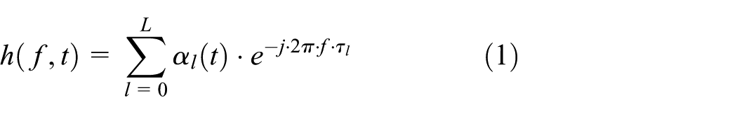
where
Utilizing equation (1), CPA of the received signal can be given as

DCPA can be given by

where
CPA in FZ
Based on the FZ model,13,14 we analyze the influence of the mobile obstacle on the received signal. When the mobile obstacle appears in FZ, the propagation paths of RF signals between the transceiver are divided into two types: DRL and the reflected link (RL). Furthermore, the RL is divided into static reflected link (SRL) and mobile reflected link (MRL), where SRL and MRL are caused by the reflection of the static obstacle and the mobile obstacle, respectively. Figure 1 depicts movements of the mobile obstacle in different areas, where the green solid line is the SRL, the black solid line is the DRL, and the black dotted line represents the MRL. On account of the analysis above, CSI can be expressed as

where

where

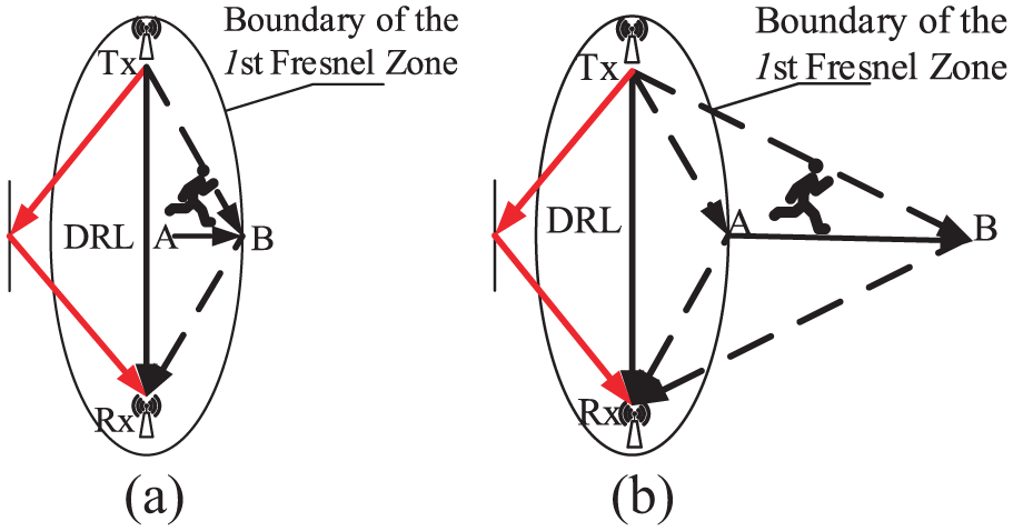
Movements of the mobile obstacle in different areas: (a) inside FFZ (IF) and (b) outside FFZ (OF).
It is known from the above-mentioned discussions, the waveform of
DCPA in FZ
DCPA when the mobile obstacle is IF
It is shown in Figure 1(a), DCPA refers to the diversification of the CPA when the mobile obstacle moves from DRL to the boundary of FFZ (during that,

where
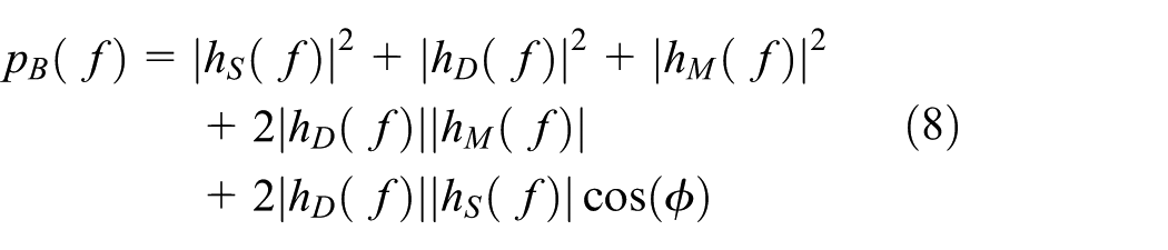
When the mobile obstacle is on the DRL,
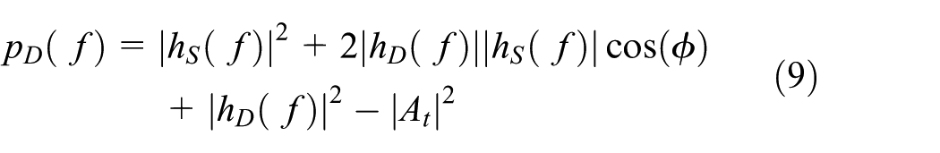
Considering equations (8) and (9), DCPA is defined as

DCPA when the mobile obstacle is OF
Figure 1(b) depicts the mobile obstacle starts at the boundary of FFZ and moves away from the FZ center. As can be seen from equations (3) and (6), when the mobile obstacle is OF, DCPA can be represented as

Typical environmental settings are considered in this article, including multiple static reflective obstacles and a single mobile obstacle. When the mobile obstacle is not on the DRL, then

Observations and insights on PA
According to formula (11), it can be seen that CPA varies obviously when the obstacle is moving in FFZ; then, we focus on FFZ-based CPA. In order to provide fine-grained PA information, PA is divided into three categories: the obstacle is OF, denoted LOS PA; the obstacle is IF, but not on the DRL, denoted SLOS PA; and the obstacle is on the DRL path, denoted NLOS PA, as shown in Figure 2. FFZ is an ellipsoid whose foci are the transmitter and the receiver;

Model of different PA: (a) LOS PA, (b) SLOS PA, and (c) NLOS PA.
Design
Overview
Figure 3 illustrates the system architecture of Asor. First, we collect CSI with CSI collector equipped with Intel 5300 NIC, and then CPA and DCPA are derived with CSI analyzer according to the FZ theory. Second, CPA and DCPA sub-detectors are proposed to detect the PA based on CPA and DCPA. Note that each sub-detector shows unique advantages and disadvantages in mobile and static scenarios. It is found that CPA detector has poor performance in the mobile scenario and DCPA detector fails to work in the static scenario. To solve this problem, we present Asor which exploits HMM to obtain the optimization results for each sub-detector and selects the best of two optimization results by comparisons as the final detection result.

System architecture of Asor.
CPA detector
We perform CPA detector in two stages. First, CPA is updated based on Kalman filter (KF). Second, based on the updated value

where
According to equation (13), CPA identification results can be expressed as

where
DCPA detector
As we know, CPA is only for the static scenario; in order to solve this problem, DCPA detector is presented based on the analysis result
Then, DCPA detector detects PA precisely based on
If

If

Asor
In terms of analyses on CPA and DCPA detectors as mentioned above, neither of them work in a general scenario. In our experiments, it is found that the current PA state is usually related to the previous one; then, we present Asor based on HMM to identify PA adaptively according to the results of CPA and DCPA detectors.
HMM-based state structure of Asor
HMM is used to describe a Markov process with underlying hidden states. In this article, we define the real PA (RP) as the hidden state, and the outputs of the two sub-detectors are the observation states. The two current observation states and the previous hidden state are combined with their respective state emission probability matrices and transition probability matrices; then, their respective hidden states are obtained. Comparing the two hidden states, we can get the best hidden state, which is regarded as Asor’s detection result. Figure 4 illustrates the state structure of Asor.

State structure of Asor.
In Figure 4, the outputs of DCPA and CPA detectors at time
State transition probability matrix design
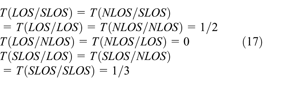
We can obtain
If the previous PA state is LOS, the current PA state is LOS or SLOS, not NLOS, because the mobile obstacle will not move directly from outside the ground projection area of FFZ to DRL. If the previous PA state is NLOS, it is similar to LOS PA. Based on observations and theoretical analysis above, we determine
State emission probability matrix design
Similar to

State emission probability distribution: (a) distribution of
Detection of PA based on Asor
HMM is implemented dynamically based on Viterbi algorithm to obtain the best current PA state. First, initializing PA state when
Asor’s detection algorithm.
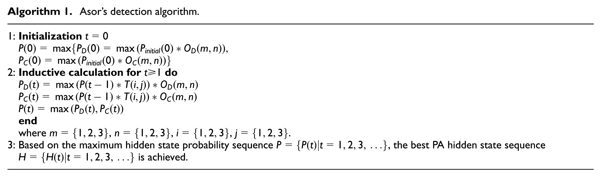
In the algorithm,
Implementation and evaluation
Experimental designs
Asor consists of a DELL laptop with an Intel 5300 NIC and an AP. We take the laptop as a receiver and AP as a transmitter. The laptop works under Ubuntu 11.04 system installed with 802.11 CSI tool. CSI data acquisition and real-time data processing are achieved utilizing this laptop. The antenna of the laptop used in this article is the internal antenna, sampling frequency of the RX is set to 20 Hz, and packet interval of the TX is 2 ms. All the comparative experiments are the mean of five rounds of experimental results. The observation time window is
System performance
This article evaluates the reliability and real-time performance of Asor. In order to demonstrate the superiority of this system, we consider LiFi 8 as the benchmark method. LiFi extracts the CSI amplitude characteristic factors of LOS/NLOS PA, respectively, to detect PA, and harnesses natural mobility to magnify the randomness of NLOS paths while retaining the deterministic nature of the LOS component. The difference with Asor is that LiFi is a statistical LOS identification scheme for commodity WiFi infrastructure.
System reliability
In this article, the accuracy rate is defined to carry out the performance evaluation of DCPA detector, CPA detector, and Asor; the accuracy rate is given as

where
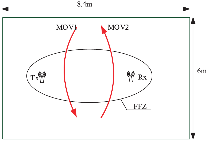
Mobile scenario testing
The mobile scenario testing is conducted in a corridor with an area of 8.4 × 6, where MOV1 and MOV2 represent the mobile obstacle traveling through LOS, NLOS, and SLOS PAs, as shown in Figure 6.
Mobile scenario.
Static scenario testing
Figure 7 shows the static scenario setting; the static scenario testing is also conducted in a corridor with an area of 8.4 × 6. The static scenario setting is divided into two scenarios, where static scenario 1 represents that the mobile obstacle is at a standstill, as shown in Figure 7(a), and static scenario 2 indicates that the mobile obstacle is moving in LOS, NLOS, or SLOS PA all the time, as illustrated in Figure 7(b). It is known in Figure 7(a) that there are 20 different positions, where eight positions are in LOS PA (denoted by black circle position), four positions are in NLOS PA (indicated by red circle position), and eight positions are in SLOS PA (represented by green circle position). Figure 7(b) describes that the mobile obstacle is walking in different PAs, where S1 and S2 represent the mobile obstacle moving in LOS PA, and S3 and S4 are the mobile obstacle moving in SLOS PA. S5 is the movement of the mobile obstacle in NLOS PA.

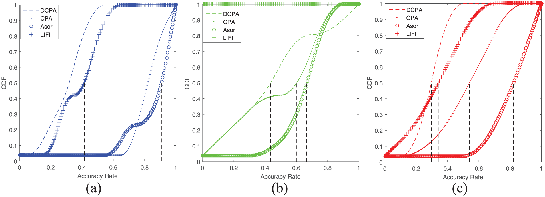
Detection performance in mobile scenario: (a) LOS, (b) Semi-LOS, and (c) NLOS.
To demonstrate the advanced performance of Asor, we compare our scheme with LiFi as shown in Figure 8. It is found that the detection performance of Asor exceeds the others, and the accuracy rates in LOS/NLOS PA are as high as 90%, while LiFi is almost invalid in the mobile scenario. The reason is that the mobile obstacle would stay in the SLOS area for a short time in most scenarios. SLOS PA is the transition region from LOS to NLOS; therefore, the detection performance of Asor is declined to 50% in SLOS PA, even though it is still higher than the performance of DCPA detector, CPA detector, and LiFi.

Static scenarios: (a) scenario 1 and (b) scenario 2.
As shown in Figure 9, in static scenario 1, detection results of Asor are more accurate than the other three detectors in LOS/NLOS/SLOS PA. In particular, the overall accuracy rates of Asor are about 90% in LOS/NLOS PA, which greatly outperforms LiFi. The performance of Asor declines in SLOS PA; however, the median

Detection performance in static scenario 1: (a)
Figure 10 shows the comparisons of four detectors in static scenario 2. As can be seen from Figure 10, the median accuracy rates of Asor in static scenario 2 are almost the same as those in static scenario 1. It can also be found that the detection performance of Asor is superior to the other three. Especially, in NLOS PA, Asor outperforms LiFi, DCPA detector, and CPA detector, with an average improvement of more than 48%, 52%, and 28%, respectively. In LOS PA, the median accuracy rate of Asor is as high as 90.94%; however, the accuracy rate of LiFi is 41.56%. In a nutshell, Asor is optimal both in the mobile and static scenarios.
Detection performance in static scenario 2: (a)
Real-time performance
In order to verify the real-time performance of Asor, we carry out the tracking experiment in the corridor, which covers LOS, NLOS, and SLOS PAs, as shown in Figure 11.

Trajectory tracking experiments: (a) indoor scenario and (b) comparisons.
Figure 11(a) demonstrates the person’s trajectory, where the green part of the trajectory represents SLOS PA, the red part denotes NLOS PA, and the black part demonstrates LOS PA. Figure 11(b) depicts the comparisons between detection results of three detectors and RP. It is found in Figure 11(b) that Asor’s detection results are the most similar to RP, and it can also be deduced that Asor identifies PA accurately in real time.
Application
We have evaluated the detection accuracy of Asor as mentioned above. With accurate PA identification, the performance of a plethora of upper-layer applications can be significantly improved (e.g. localization, activity recognition, gesture recognition). In this section, we take Splicer 15 as a benchmark to demonstrate the capability of Asor.
Case study overview
In terms of the detection results of Asor, Aloc proposes an adaptive TOF algorithm of DRL. When PA is LOS, the arrival time corresponding to the highest pulse of PDP is used as the TOF of DRL, as shown in Figure 12(a), where L1 to L6 represent the leakage pulses of inverse fast Fourier transform (IFFT). When PA is NLOS, DRL usually arrives earlier than the highest pulse; however, as demonstrated in Figure 12(b), the leakage pulses also come earlier than the highest pulse, which results in the inability to directly derive the TOF of DRL. Through a large number of experiments in NLOS PA, it is found that the leakage pulses are much smaller than the pulse of DRL as shown in Figure 12(b). If RL1 indicates the highest pulse, therefore, the arrival time of the highest pulse before RL1 is taken as the TOF of DRL.

PDP in LOS/NLOS PA: (a) PDP in LOS PA and (b) PDP in NLOS PA.
In the case of a single AP, Splicer is unable to localize only with the TOF of DRL. In order to get the AOA of DRL, Aloc adopts the algorithm in Zheng et al. 20 to calculate AOA. First, a mobile object stands at different positions around the AP. Second, by analyzing the CSI obtained from different positions, one position is derived that has the most significant impact to the wireless channel, and then it is determined that this position is on the DRL. Finally, the AOA of DRL is achieved by this position. In a nutshell, based on the TOF and AOA of DRL, Aloc can achieve positioning accurately with only one AP.
Results
For the purpose of evaluating the performance of Aloc, we perform experiments in a corridor (shown as Figure 13(a)) and a council chamber (shown as Figure 13(b)) in the static scenario, in which the positioning errors within different RX–TX distances are compared in LOS/NLOS PA, respectively. Figure 14 shows CDF of the positioning errors of Aloc/LiFi-Splicer/Splicer in LOS/NLOS PA in the corridor, where LiFi-Splicer is a LiFi-based Splicer localization system. It is known in Figure 14 that Aloc is superior to the others in LOS/NLOS PA. Figure 14(a) describes that in LOS PA, the median errors of Aloc and Splicer are almost the same; however, the positioning accuracy of Aloc exceeds LiFi-Splicer by up to 0.7 m. Figure 14(b) illustrates that in NLOS PA, Aloc outperforms LiFi-Splicer and Splicer, with an average improvement of more than 1.5 and 4 m, respectively. It can also be seen in Figure 14 that the positioning accuracy of Aloc in LOS PA is obviously more precise than that in NLOS PA, and the median error in LOS PA is below 1 m.

Experimental scenarios: (a) corridor and (b) council chamber.

Location error comparisons of Aloc/Splicer/LiFi-Splicer in LOS/NLOS PA in the corridor: (a) location error in LOS and (b) location error in NLOS.
Figure 15 gives CDF of the positioning errors of Aloc/LiFi-Splicer/Splicer in LOS/NLOS PA in the council chamber. As can be seen from Figure 15, the positioning performance in LOS PA is better than that in NLOS PA. Figure 15(a) shows that in LOS PA, Aloc and Slicer significantly outperform LiFi-Splicer by up to 2 m. Figure 15(b) describes that in NLOS PA, Aloc performs obviously better than Splicer and LiFi-Splicer on average improved by 4 and 2 m. Overall, Aloc’s median errors are far less than the others in both LOS and NLOS PAs.

Location error comparisons of Aloc/Splicer/LiFi-Splicer in LOS/NLOS PA in the council chamber: (a) location error in LOS PA and (b) location error in NLOS PA.
Figure 16 expounds the average positioning errors for Aloc/LiFi-Splicer/Splicer within different receiver–transmitter (RX–TX) distances in LOS/NLOS PA in the corridor and council chamber, respectively. As shown in Figure 16, the positioning performance of the three systems in the corridor is superior to those in the council chamber. Figure 16(a) and (c) illustrate that in the corridor and council chamber, Aloc and Splicer have the same positioning accuracy, better than LiFi-Splicer in LOS PA. Especially, in the corridor, when the RX–TX distance is 8 m, the positioning error of Aloc is less than that of LiFi-Splicer by 2 m. Figure 16(b) and (d) describe that in the corridor and council chamber, Aloc greatly outperforms Splicer and LiFi-Splicer with any RX–TX distances in NLOS PA. In a short, Aloc can accurately locate in both the council chamber and corridor.

Performance of Aloc/Splicer/LiFi-Splicer at different RX–TX distances in the corridor and council chamber: (a) performance in LOS PA in the corridor, (b) performance in NLOS PA in the corridor, (c) performance in LOS PA in thecouncil chamber, and (d) performance in NLOS PA in the council chamber.
Related works
The related work of PA identification technology can be divided into two categories: indoor localization and activity recognition.
Indoor localization
Indoor localization techniques can be classified into three general categories: AOA-based indoor localization, range-based indoor localization, and fingerprint-based indoor localization. The AOA-based indoor localization utilizes multiple antennas with the capacity to measure the angles, and determines the target location according to the geometrical properties. In order to achieve localization, ArrayTrack 2 proposes a spatial smoothing algorithm to find the AOA of the DRL. Based on ArrayTrack, a super-resolution AOA estimation is investigated to obtain decimeter-level indoor positioning. 3 The range-based indoor localization usually measures the TOF of DRL to implement positioning. CUPID 21 extracts the TOF and AOA of DRL from CSI, effectively avoiding the influence of multipath reflections; Chronos 18 and Splicer 15 expand the bandwidth by splicing CSI measurements to derive high-resolution PDP and then accessing to precise TOF to achieve fine-grained positioning. The fingerprint-based indoor localization adopts signal features to map location information. FIFS 22 combines CSI with the spatial diversity of multi-antennas as indoor positioning fingerprints and proposes a coherence-bandwidth-enhanced probability algorithm with a correlation filter to map objects into the fingerprint database. RSS, the transmitted power, and channel information are employed to construct an integrated fingerprint, and a cosine-similarity-based matching algorithm and an enhanced particle filter mechanism are designed to obtain accurate positioning and tracking; 23 CSI-MIMO 24 jointly integrates CSI with Multiple-Input Multiple-Output (MIMO) information as fingerprints to localize precisely. Indoor localization methods mentioned above all assume a clear pre-knowledge on PA, especially PA is unchanged during the whole localization. However, the assumption is unpractical because PA varies along with the time. As an available middleware of indoor positioning algorithms, the method proposed in this article presents a dynamic identification on PA, which leads to improvements of robustness and extensibility of positioning algorithms.
Activity recognition and gesture recognition
In WiFall, 5 fall detection algorithm is proposed by investigating SVM and Random Forest algorithms to classify different human activities. A smoking detection is put forward through designing a foreground detection method based on motion acquisitions, which extracts meaningful information from multiple noisy subcarriers. 6 An adaptive and robust intrusion detection system leveraging CSI from commodity WiFi is presented. 7 WiFinger 4 identifies finger-grained features of the gesture with CSI. The technologies aforementioned can achieve fine-grained positioning in LOS PA; however, they almost fail to work in NLOS PA.
Conclusion
We design an HMM-based real-time PA detector, Asor, which achieves real-time, fine-grained PA identification in both the static scenario and the mobile scenario. Asor consists of a laptop equipped with Intel 5300 NIC and an AP without any hardware modification. In order to verify Asor, an Aloc, is proposed. Evaluations are conducted in many scenarios. Experimental results demonstrate that overall LOS/NLOS PA identification rates are as high as 90% in both the static scenario and the mobile scenario. Decimeter-level accuracy can be obtained by Aloc in LOS both in the corridor and in the council chamber. However, it will be the future work that the fixed time window does not work when PA changes slowly, and NLOS identification rates are worse than the LOS.
Footnotes
Handling Editor: Yu Wang
Declaration of conflicting interests
The author(s) declared no potential conflicts of interest with respect to the research, authorship, and/or publication of this article.
Funding
The author(s) disclosed receipt of the following financial support for the research, authorship, and/or publication of this article: This work is supported in part by the Hebei Province Natural Science Fund Program under Grant No. F2016203176, National Natural Science Foundation of China under Grant No. 61772453, Youth Foundation in Basic Research of Yanshan University under Grant No. 16LGA009, and Technology Foundation for Selected Overseas Chinese of Hebei Province under Grant No. CL201625.