
Abstract
The vision-based localization of rotor unmanned aerial vehicles for autonomous landing is challenging because of the limited detection range. In this article, to extend the vision detection and measurement range, a hierarchical vision-based localization method is proposed for unmanned aerial vehicle autonomous landing. In such a hierarchical framework, the landing is defined into three phases: “Approaching,”“Adjustment,” and “Touchdown,” in which visual artificial features at different scales can be detected from the designed object pattern for unmanned aerial vehicle pose recovery. The corresponding feature detection and pose estimation algorithms are also presented. In the end, typical simulation and field experiments have been carried out to illustrate the proposed method. The results show that our hierarchical vision-based localization has the ability to a consecutive unmanned aerial vehicle localization in a wider working range from far to near, which is significant for autonomous landing.
Introduction
Unmanned aerial vehicles (UAVs) are popular among civil and military situations that are hazardous to human operators. Automated localization is therefore highly desirable while the vehicles are landing on stationary or moving platforms. Specifically, this refers to UAVs that have the ability to localize themselves using information from onboard sensors, such as Global Positioning System (GPS), Inertial Measurement Unit (IMU), and vision. The use of vision sensors for localization has many advantages. Currently, the GPS, IMU, or their combination is the most common method used to determine a UAV position. However, these require the transmission of information between the air vehicle and the landing platform. Furthermore, vision sensors are mostly passive and do not rely on an external signal. It is worth noting that vision sensors can have millimeter-level accuracy and can determine not only the distance but also the relative orientation between two objects. This article describes a complete vision-based process and the key enabling technologies for a successful landing.
In recent years, there has been a wealth of work and different vision-based methods available for this type of application. These include both feature-based methods and direct methods. Some of the approaches require prior knowledge of the targets, and some extract information from the surroundings in real time. However, keeping detection range as well as precision is difficult for each single vision-based method because of a limited camera device. It means that UAVs could hardly keep detecting features at single scale from the reference object when the UAV altitude changes continuously from high to low. Moreover, UAVs at different altitude have a fixed field of view. For example, the UAV is too far away from the landing to detect some features or patterns. Hence, to solve this problem, a strategy using hierarchical vision-based localization is advised for UAV landing, which is able to extract reliable visual cues in different landing phases.
This article describes a hierarchical localization demonstration in which a rotor UAV determines its own position and attitude relative to a designed landing object using only the onboard camera. A planar textured image pattern is employed as the landing object, which is composed by a set of signs with the scale information. The reference object enables easy detection and is able to provide sufficient information for UAV pose recovery. The main contributions of this article can be summarized as follows: in order to ensure precision and range of the vision-based localization, a hierarchical vision localization framework that employs various artificial markers with different scales as visual feature for a landing. The landing process has been defined into three phases, “Approaching,”“Adjustment,” and “Touchdown.” For different landing phases, the corresponding feature can be extracted from the designed landing object, and the UAV pose recovery algorithms using the extracted feature have been presented. The hierarchical vision localization framework is proved to be very beneficial for an open landing. The hierarchical framework has been tested and evaluated by simulation and field experiment. The results show that the proposed method is able to estimate the UAV’s position and orientation in a wide vision range. As a result, the hierarchical framework is pragmatic for autonomous landing.
The remainder of the article is organized as follows: In section “Previous work,” some related works are introduced. The designed landing object and the corresponding feature detection and pose recovery algorithms are introduced in section “Object detection and pose recovery.” Section “A hierarchical vision-based localization framework” describes a hierarchical vision-based localization framework to extend the vision range. Section “Experiments and analysis” presents the experiments and results to illustrate the proposed hierarchical vision-based framework. Finally, the conclusions are presented in section “Conclusion and future work.”
Previous work
Currently, vision-based localization is one of the most adopted ways to actively study UAV autonomous landing. In general, an object is designed as the landing reference to enable clear detection by UAV onboard vision and can provide structure information for the UAV pose recovery with respect to the landing spot. 1
In related works, one assumes that the pattern and size of a landing object are given. And the relative localization can be acquired by its projection in the view of onboard vision. In particular, depending on the inertia moments of the object in the image, it is sufficient to distinguish the landing object from background. 2 The state of the UAV is calculated by matching the acquired real-time image with a dataset of stored labeled images that have been calibrated offline in advance. Image blurring would reduce the extraction accuracy of cooperative markers. As a result, a special pattern consisting of several concentric white rings on a black background was designed as the observed object so that at least one ring can be captured clearly. 3 Each of the white rings is recognized with a unique ratio of its inner to outer border radius. A pose estimation algorithm based on the feature lines of the cooperative object was reported, 4 where infrared (IR) light was employed to reduce the influence of weather and feature lines, and the vanishing lines were thought to be insensitive to image blurring. An initial 5 degree-of-freedom (DOF) pose of the camera coordinate frame for the UAV with respect to a landing pad could be obtained using the quadratic equation of the projected ellipse. 5 The IMU data were integrated to eliminate the remaining geometric ambiguity. The final DOF of the camera pose, its yaw angle, was calculated by fitting an ellipse to the projected contour of the letter “H.” The homography between the image frame and the object reference plane was also used to calculate the UAV initial pose. 6 With the four correspondences between the world plane and the image plane, the minimal solution for the homography could be estimated. Reported in Martinez et al., 7 a similar work decomposed the homography between the current and previous frames to accumulate for ego-motion estimation. The relative pose between the current and the previous frames could be tracked by observing a structured-unknown object.8–10 Based on speeded-up robust features (SURF) feature descriptors and fast approximate nearest neighbor search (FLANN) matcher, a template matching method 11 was presented to determine the relative position of the landing target. Also, artificial neural networks (ANN) have been employed to estimate the state of the landing UAV in Moriarty et al. 12 Similar to our work, Araar et al. 13 have designed an adequate pad to extend the detection range. The proposed pad is composed of patterns of different sizes, permitting their detection from high as well as very low altitudes. For the application purpose, the main advantage of the approach in Benini et al. 14 is the use of a GPU for detecting the marker in order to achieve onboard high-frequency pose estimation and marker detection. The use of the GPU allows fast image analysis even in cluttered environments that otherwise would be difficult to achieve with CPU-based algorithms. In Vetrella et al., 15 a guidance approach using the improved intrinsic tau guidance theory was presented to create spatio-temporal four-dimensional (4D) trajectories for a desired time-to-contact with a landing platform tracked by a visual sensor.
In another case, there is no reference object for UAV landing and the localization could be achieved by sensing the surrounding nature scene. In this method, a batch of non-artificial feature was presented. Typical optic-flow-based methods16–20 are used to track or stabilize the UAV pose. This strategy involves adjusting the speed of approach to maintain the magnitude of the optical flow generated from the ground. A biological guidance system, reported in Forster et al., 21 detected and analyzed visual cues from the natural environment, such as the horizon profile and sky compass. The image coordinates extrapolation (ICE) algorithm 22 has been used to calculate the pixel-wise difference between the current view (panoramic image) and a snapshot taken at a reference location to estimate the UAV three-dimensional (3D) position and velocity real time. An autopilot based on an optic-flow-based vision system is reported in Kendoul et al. 23 and Denuelle et al., 24 where the optic flow is calculated and used for autonomous localization and scene mapping. The relevant controller using the vision information is also discussed in detail in these works. The image-based visual servoing (IBVS) has been used to track the platform in two-dimensional (2D) image space and generate a velocity reference command used as the input to an adaptive sliding mode controller, which was reported in Lee et al. 25 In Ho and Chu et al., 26 a fully autonomous system using the visual measurements was presented for a quadrotor UAV to perform automatic landing task. In Yang et al., 5 the landing site was defined by a template image and identified using the matching of detected oriented FAST and rotated BRIEF (ORB) features. The relative pose was estimated from a parallel tracking and mapping (PTAM) thread, by matching the landing site features to the PTAM map points. A monocular vision-based autonomous landing system 27 was implemented for emergencies and unstructured environments. 3D features and a mid-pass filter have been combined to remove noise and construct an elevation map in this system.
In addition, some other ways have been applied, such as stereo vision28,29 and vision and IMU combination.30,31 It is assumed that the IMU has the ability to provide a good scale estimation for the mono-vision system. Wenzel et al. 32 used a Wii remote IR camera as main sensor, which allows robust tracking of a pattern of IR lights in conditions without direct sunlight. In our preliminary work, one multi-view navigation system 33 has also been reported, that employed hybrid vision measurements to estimate UAV pose.
Based on the work described above, it is therefore thought that feature detection and recognition would be a key issue with regard to localization precision. Moreover, for a complete landing, the vision should have the ability to work well from far and close with the landing spot. To extend vision detection and localization range, a hierarchical method is studied in this work.
Object detection and pose recovery
The UAV localization with respect to an object in an unknown environment is a complex but solvable problem that can be achieved with either single camera or stereo cameras. In this work, a set of friendly artificial markers have been set to construct a landing object, as shown in Figure 1. The corresponding feature detection and pose recovery methods are explained in the following section.

Landing object and feature description inside.
Feature description and detection method
One desires to calculate the UAV position and orientation reliably using the designed artificial markers of the landing object. Inspired from QR code popularly applied in the field of current information recognition, three artificial markers (black and white rectangles), denoted as Top, Right and Bottom, can be detected and recognized robustly. First, each marker is segmented from the background using contour extraction and statistics. We converted original gray image to binary format by thresholding operation. The “findContours” function in OpenCV has the ability to retrieve contours from the binary image using the algorithm. 34 Contours can be explained simply as a curve joining all the continuous points along the boundary, having same color or intensity. They are used for fiducial marker detection and recognition. Thus, there would be two contours to be detected for each boundary between white and black. It means that a fixed number (six) of contours would be obtained for each complete fiducial marker, as shown in Figure 1. These markers can be recognized robustly by counting the detected contours. The contour c1 which has five child-contours (c2-c6) is thought to be the boundary of one fiducial marker. Using such a way, other two fiducial markers can also be recognized.
Then, Top marker can be recognized by calculating the straight-line distances between any two markers. The distances between the markers are
As a result, redundant feature corners can be extracted from these fiducial markers. Since the actual sizes of these markers are assumed to be known, the corners can be used as corresponding points between the reference object and its image plane for the following pose extraction part. So far, all feature points from the three fiducial markers can be determined using the above operations to build a constant 3D coordinate on the landing object, which enables a unique yaw for UAV landing.
Pose recovery method
The UAV pose (position and orientation) can be extracted by homography decomposition. Here, the homography is a non-singular 3 × 3 matrix
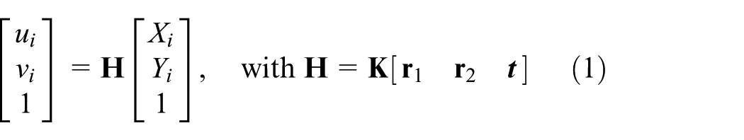

Object-to-image plane homography based on the camera projection model.
Using the extracted corresponding points, one rough solution about the matrix
The matrix

where
With this,
A hierarchical vision-based localization framework
Hierarchical localization
Except for the vision detection or localization algorithms, the employed camera parameters that involve image resolution and focal length can influence the result of the UAV pose calculation as the detecting range changes. To solve the problem, a hierarchical vision-based localization framework is presented. In our work, a complete UAV landing is considered to be divided into three phases: “Approaching,”“Adjustment,” and “Touchdown.” Different visual features and the corresponding algorithms are selected for three UAV landing phases, as shown in Figure 3. These phases are switched by considering current UAV height with respect to the landing platform, object projection ratio, and so on.

Hierarchical vision-based localization framework.
At the beginning of a landing, the UAV is thought to be so far away from the reference object that the limited onboard vision can hardly capture fiducial markers clearly. At this point, the external contour or boundary of the landing object can be detected by vision. When the UAV is far away from a landing object in a real environment, many other objects except for the reference object can be seen by the onboard camera, such as a building. As shown in Figure 1, compared to the background, the landing object has a distinctive color feature. Thus, before contour detection, a color-based segment setup is acquired to remove the background. And the remaining noise such as irregular blobs can be filtered by shape analysis as the landing object is designed to be a four-vertex polygon. The landing object is thought to be the longest closed contour with four control vertices. It means that the object contour can be approximated using one four-vertex polygon. As 2D image feature, these vertices of the contour are extracted and used for the UAV pose calculation. As a result, this phase is called “Approaching,” where the image contour of the landing object is used to provide the relative motion information for the UAV.
In the landing phase “Adjustment,” the flying vehicle is thought to be sufficiently close to the landing object when the artificial markers can be detected clearly. In our field landing experiment, the landing object with an actual squared size of 0.85 m × 0.85 m and a 1080-p camera are employed. As a result, it is found that the artificial markers begin to become detectable gradually in the view of the onboard vision when the UAV altitude is below 7 m. Using the corresponding feature points extracted from the markers, the relative position and orientation of the UAV can be calculated through the homography-based method introduced in the previous section. The obtained real-time pose can be used to adjust the UAV to an appropriate state for precise landing. In particular, this phase is helpful when the UAV is required to touch down in a certain orientation, such as charging or ranking.
When the UAV is near the landing, the complete object could be hardly captured due to the limited view of the onboard vision, as shown in Figure 3(c). This phase is called “Touchdown,” in which either object-based or marker-based method in the first two phases is out of work. Therefore, as soon as the markers cannot be detected any more and the current height is near the ground, it is considered that the UAV comes in the “Touchdown” phase. In this “Touchdown” phase, an optical flow-based pose tracker is designed to determine the current pose by tracking the optic-flow points between the current and the previous image frames. A Harris corner detector is used to extract feature points from each image. Using the iterative Lucas–Kanade method with pyramids, these points between previous and current frames can be matched. As we know, when the UAV is near the landing object, all acquired images are occupied by the planar object. That means almost all feature points are from the plane. Hence, the matching points can be used to calculate the homography between previous and current frames. And the relative pose change can also be obtained by homography decomposition. To calculate the current pose with respect to the landing object, the homography between the current frame

In summary, different feature detection and pose extraction algorithms are presented for three corresponding landing phases, which constitute a hierarchical vision-based localization framework. The framework is practical and can guarantee a consecutive pose result for UAV landing.
False pose estimation detection
Failure detection of the visual parts is desired to ensure ongoing functionality of the whole framework. We explain the detection of vision failures in the following sections.
It should be noted that the rotation between the body (inertial) frame and the visual frame

where

Due to the fact that the drift is slow, abrupt jumps can be identified in the measured orientation
Experiments and analysis
Simulation in Gazebo
This section shows that some UAV localization tests are done using the hierarchical vision-based system. In the simulation, a virtual camera with a resolution of 800 × 800 pixels and a framerate of 30 Hz is installed to look downward relative to the UAV. It is assumed that the camera is calibrated, and the intrinsic parameters are known. The designed landing object is placed on the top of a ground vehicle to form a landing platform. The relative height of the platform is approximately 0.5 m. All the calculations are programed using receiver-only synchronization (ROS) nodes, and all the experiments are executed by Gazebo, 37 which can export the ground truth of the UAV state. Figure 4(a) shows the simulated UAV landing scene. The experiments begin when the UAV flies over a landing object. The center and size of the three squared fiducial markers are assumed to be known in advance.

UAV vision sensor system and landing object: (a) simulation in Gazebo and (b) field experiment.
The objective of the first flight experiment is to verify the designed landing object and the corresponding algorithm for the UAV pose recovery and adjustment. In the experiment, the UAV is required to perform a series of movements, such as forward, backward, left, right, up, and down, and several 360° spins. These movements are typical, involving all possibilities of a given flight. The localization result acquired from the vision and the ground truth of the UAV state are shown with time in Figure 5. Since the landing object is set on a ground platform with a height of 0.5 m approximately, it is reasonable that there is a constant bias between Zvision and Zground. Zvision is the estimated height with respect to the object, and Zground is the real height with respect to ground, which can be seen in Figure 5(a). The corresponding error is also analyzed, and the calculated position has a small error with a root mean square error (RMSE) of 0.0239 m. In the same way, the RMSE of the calculated orientation is 0.0818 rad, shown in Figure 5(b). The results show a good performance for the proposed vision-based pose recovery method with our designed landing object.

Vision-based pose recovery using the designed landing object: (a) 3D position with respect to the landing object (m) and (b) the orientation involving the roll, pitch, and yaw angles (rad).
Also, the employed feature detection and extraction algorithms have been tested and the results are shown in Figure 6. In the beginning “Approaching” phase of a landing, the detected object is so small in the field-of-view of the UAV which is only reliable information to guide the UAV. Accordingly, the four vertices extracted from the contour could be used to calculate the UAV pose, as shown in Figure 6(a). In the “Adjustment” phase, and the artificial markers of the landing object can be captured and detected completely, which is shown in Figure 6(b). Finally, as the relative distance between the UAV and the landing object reduces, either the contour or the marker is almost out of the onboard vision. At this moment, the pose tracker shown in Figure 6(c) starts generating a set of optical flows and ensures the final pose in the “Touchdown” phase.

Real-time captured images at three landing phases and the corresponding feature detections: (a) approaching phase, (b) adjustment phase, and (c) touchdown phase.
Field experiment
Another field landing experiment has also been carried out to illustrate the performance of the hierarchical vision-based framework presented in the previous section. In the experiment, the employed UAV is a six-rotor aircraft that can fly autonomous according to a predefined GPS trajectory, as shown in Figure 4(b). The aircraft uses a proportional–integral–derivative (PID)-based nested controller and is controlled by onboard GPS and IMU sensors. Used for a reference, an XSENS product (MTi-G-700) 38 is a fully integrated solution that includes a GPS receiver and an inertial navigation system (INS). The MTi-G-710-GPS/INS is thus capable of not only outputting GPS-enhanced 3D orientation, it can also output attitude and heading reference system (AHRS)-augmented 3D position and velocity, so that velocity and position accuracy significantly improve with respect to the accuracy of the GPS receiver alone. Furthermore, it provides 3D sensor data, such as acceleration and magnetic field. For the reference system, the employed XSENS module has a 450 deg/s full range gyroscope and a 200 m/s2 full range acceleration. As a result, the dynamical errors in roll/pitch and yaw are 0.3° and 1.0°, while the horizontal and vertical positioning accuracy are below 1 and 2 m, typically. Data generated from the strapdown integration algorithm (orientation and velocity increments Δq and Δv) are available, as all other processed data, at 100–400 Hz with a low latency (<2 ms). As the onboard vision, a motion camera GOPRO4 with a resolution of 1080 p and a refresh rate of 50 Hz is installed to look downward relative to the UAV. The camera has been calibrated in advance. The designed landing object with a squared size 0.85 m × 0.85 m is placed on the ground and the relative height is approximately 0 m. In the following field experiments, the vision measurements have been compared with the integrated GPS/INS system.
The aircraft starts landing on the landing object from a height of 20 m, and the results of the total process has been recorded. The pose solutions from the three landing phases are displayed using different colors in Figure 7. For the flight test, the rotation

Proposed hierarchical vision-based localization: (a)–(c) 3D position (X, Y, Z) with respect to the landing object (m); (d)–(f) orientation angles involving roll, pitch, and yaw (rad).

Calculated rotation

Localization error analysis of different landing phases (Approaching, Adjustment, and Touchdown): (a) 3D position error m; (b) orientation angle error (deg).
Conclusion and future work
In this article, to extend the detectable and measurable range, a hierarchical vision-based localization method has been presented for UAV autonomous landing. A landing object was designed to provide various visual reference features at different scales for onboard vision from high as well as low altitude. Based on the designed object, the landing was defined into three phases: “Approaching,”“Adjustment,” and “Touchdown.” And for the three phases, the corresponding feature extraction and pose recovery algorithms have been introduced. Simulation and field experiments have been performed and analyzed to illustrate the performance of the proposed hierarchical vision localization. Although this article is a preliminary work, such a hierarchical method is thought to be significant as one of the visual guidance for UAV landing. Seamless and smooth pose estimation and visual servoing using the acquired vision measurements will be focused in the future.
Footnotes
Acknowledgements
Q. Li would like to acknowledge the support of Virginia Microelectronics Consortium (VMEC) research grant.
Handling Editor: Jinsong Wu
Declaration of conflicting interests
The author(s) declared no potential conflicts of interest with respect to the research, authorship, and/or publication of this article.
Funding
The author(s) disclosed receipt of the following financial support for the research, authorship, and/or publication of this article: The work reported in this paper is the product of several research stages at George Mason University and Wuhan University of Technology has been sponsored in part by the Natural Science Foundations of China (51579204 and 51679180) and Double First-rate Project of WUT (472-20163042).