
Abstract
Wireless charging technology has been developing rapidly in recent years and has been used to deliver power and provide a new source of energy for wireless rechargeable sensor networks. With current solutions, charging is usually done by a mobile vehicle equipped with a charger, which needs to be waiting on site until the sensor is properly charged. It is possible that some sensors drain their power while the charging vehicle is serving the other. Accordingly, we proposed a solution that uses a single charging vehicle equipped with multiple battery cells, which we call the separable charging array. The battery cell can be unloaded on site with sensor, while the vehicle carries on its mission. A scheduling algorithm, a revised earliest deadline first algorithm, is proposed to work with this new model. In this study, we will demonstrate that the idea of equipping charging vehicle with separable charger array is feasible. In addition, our simulations indicate that the revised earliest deadline first scheduling algorithm does improve the earliest deadline first scheduling algorithm significantly with only minor overhead in scheduling computation time and very few extra chargers. Some modified variations of the proposed revised earliest deadline first algorithm will also be discussed and evaluated.
Keywords
Introduction
Wireless sensor networks have been widely used in collecting data in various fields like military, agricultural production, ecological monitoring, medical services, industrial production, intelligent transportation, and many more applications. 1 However, energy drain due to the limitation in battery power with the sensor nodes has always been one of the major issues that results in the eventual cut-off of mission. Accordingly, a WSN that possesses the battery recharging capability, the wireless rechargeable sensor network (WRSN), has emerged to become one of the hot areas in current WSN researches. 2
A WRSN needs wireless chargers to transfer energy to the battery of sensors. The modes of charging may be through static charger 3 or mobile vehicle(s) equipped with wireless charger 4 (will be referred to as charging vehicle hereafter). The latter mobile charging vehicle option, though may be having limitations on space, time, and energy, appears to be a more flexible, efficient, and lower cost solution compared to the stationary charging method. 5 Among the many proposed schemes, the main difference was in the number of charging vehicles. However, solutions with multiple vehicles may be too costly, while the single vehicle models may induce long delay in practical charging. Accordingly, the above-mentioned proposals may only solve partially the WRSN energy supplement problem and usually may not be capable of meeting all the urgent charging demand of sensors, which may eventually shorten the lifetime of a WSN.
In this article, we proposed a new WRSN model, which includes a single charging vehicle with separable charger array, along with a wireless charging scheduling strategy designed to meet the charging demand of sensors in the network. The model can ensure batteries of the sensors being charged not just in time, but in a very efficient way. The proposed scheme assumes that all the sensors’ charging requests transported to the base station, which then calculates and plans an (hopefully) optimal scheduling trip for the charging vehicle. The charger array is then loaded to the vehicle, which starts its mission from the base station and unloads charging cell to the requested sensor along the planned route until all the charging demands have been fulfilled. The aforementioned procedure is what we called the forward charging phase. The charging vehicle then initiates the backward cell recollecting phase by picking up as many as possible the chargers that have finished their tasks on its way back to the base station. The advantage of the above proposed new WRSN model is that charging vehicle needs not to wait while the sensor battery being charged and moves on to the next sensor. In other words, the charging of sensor battery and the moving of the vehicle can all be happening simultaneously and thus greatly increases the charge efficiency and also prolongs lifetime of the WSNs.
The above-mentioned forward charging algorithm is based on the revised earliest deadline first (REDF) algorithm (a revised version of the earliest deadline first algorithm 6 ), and will be the focus in this article. On the other hand, a very simple and straightforward backward chargers recollecting algorithm is also proposed only to demonstrate and make the whole idea complete. The main concern in this phase would be restoring as many charging cells as possible without affecting its next forward charging mission. Simulations are conducted and compared to the EDF scheduling to evaluate the performance of the proposed WRSN model. The results indicate that the REDF scheduling algorithm may significantly improve upon the EDF scheduling with only minor overhead in the computation time and very few extra chargers.
The rest of this article is organized as follows. Section “Related work” reviews some researches that are related to our work. Section “WRSNs with separable charger array” provides detailed description on the proposed new WRSN model and both of the forward charging and backward recollecting algorithms. In section “Simulation results,” the simulation results, together with corresponding analysis and comparisons, of our proposed WRSN model and algorithms are shown. Some summaries and conclusions are given in section “Conclusion and discussion.”
Related work
To prolong the lifetime of a WSN, new technologies have been developed to wirelessly recharge the sensor nodes. As an example, this may be done through inductive coupling/charging, which delivers electrical energy using magnetic coupling between the coils of the charging and charged devices tuned to resonate at the same frequency. 7 A lot of researches have been conducted on this so called WRSN, in both industrial and academic areas. When it comes to wireless charger deployment strategies, there are generally two options: placing the charger stationarily or transporting the charger with mobile vehicle.3,4 However, due to the range of wireless power transmission and cost, the stationary charger solution may not be as feasible as compared to energy replenishment through mobile wireless chargers. 5 Accordingly, the latter option appears to be a more flexible, efficient, and lower cost solution. In this section, we will focus mainly on reviewing the work related to the wireless mobile charger deployment and scheduling algorithms.
P Cheng et al. 4 were the first in addressing jointly the movement of radio frequency identification (RFID) readers for power provision and the scheduling of sensor nodes for optimal quality of monitoring (QoM). Three application scenarios, including (1) the reader travels at a fixed speed for charging and sensor nodes collect energy in an aggressive way, (2) the reader stops and charges sensor nodes for a pre-defined time while it travels periodically and sensor nodes also aggressively consume energy, (3) the reader acts the same as (2), but sensor nodes are capable of adopting optimal duty cycle scheduling for maximal QoM. Both analytical and simulation results are shown to demonstrate that the optimal QoM has been achieved.
Y Shu et al. 8 identified velocity control of the mobile charger, in order to reduce the total traveling time of charger and at the same time increase the effective charging time of the sensors, as a key design issue in WRSNs. They first proved that velocity control in the specified problem to be NP-hard and then developed a heuristic solution with a provable upper bound. Extensive simulations also showed the WSN network lifetime may be extended by 250% with their proposed velocity control mechanisms.
L Fu et al. 9 proposed energy synchronized mobile charging (ESync) protocol, which simultaneously reduces both of the charger’s travel distance and the charge waiting time of sensor nodes. Their algorithm operates by constructing a set of nested traveling salesman problem (TSP) tours based on the sensor nodes’ energy consumption. In each round of charging tour, only nodes with low remaining energy are involved. Based on a concept of energy synchronization, the nodes’ charging request sequence and the TSP tours sequence are synchronized. Experimentation and simulation results demonstrate that the ESync can reduce charger travel distance and nodes’ charge waiting time by approximately 30% and 40%, respectively.
M Zhao et al. 10 proposed to use a multi-function mobile device, called SenCar, to jointly optimize both energy charging and data collection through a two-step procedure. In the first step, the locations of some sensors are selected as anchor points, which the SenCar would sequentially visit to charge these sensors and collect data from the anchors and their nearby sensors. A selection algorithm is developed to search for a maximum number of anchor points with least battery power and reduce the traveling distance of the SenCar’s visit to within a threshold so as to achieve balance between sensor charging and data collection latency. The second step concentrates on improving the performance of data collection while the SenCar is around these anchor points. Their numerical results show that the two-step procedure can indeed achieve perpetual network operations and provide high network utility. S Guo et al. 11 proposed a similar protocol that also tackles the charging and data collection issues at the same time. Their algorithm first selects the anchor nodes and then the visiting sequence to these nodes, it then formulates the data collection problem into a network utility maximization problem that constrained by flow conversation, energy balance, link and battery capacity, and the bounded sojourn time of the mobile collector.
L Xie et al. 12 argued that charging sensor node one at a time may have the scalability issue and thus proposed to exploit the multi-node wireless energy transfer technology provided by magnetic resonant coupling. Their algorithm first partitions a two-dimensional plane into adjacent hexagonal cells. The charging vehicle then visits these cells and charges multiple sensor nodes from the center of a cell. Their goal was to pursue a formal optimization framework by jointly optimizing traveling path, flow routing, and charging time. The result was a provably near-optimal solution for any desired level of accuracy. In their subsequent study, 13 they investigated an interesting problem that loads the base station on the wireless charging vehicle. An optimization problem that jointly optimizes traveling path, stopping points, charging schedule, and flow routing was considered. By first assuming zero traveling time of charging vehicle, a provably near-optimal solution was developed for this idealized scenario. They later removed the zero traveling time assumption and developed a more practical solution and compared the performance gap between the two solutions.
The above listed works proposed to use only one single charging vehicle touring throughout the whole network for charging, which may work well in a small-scale environment. 14 However, in a larger network with more field to cover and more sensor nodes to charge, the option may not be feasible when considering the limited amount of energy that a single charger can carry and provide. Accordingly, the multiple charging vehicles solutions have also been extensively addressed. H Dai et al. 14 investigated the problem regarding how to find the minimum number of energy-constrained mobile chargers, and also designed these chargers’ recharging routes so that a WRSN may maintain continuous operation. They have proved that the above-mentioned problem to be NP-hard. Accordingly, approximation algorithms were proposed, together with the corresponding simulations to validate the effectiveness of their algorithms.
C Wang et al. 15 argued that combining wireless charging with mobile data collection on a single mobile vehicle may result in long data latency issue for some applications since mobile charger needs to spend some time in charging before it can upload data to the base station. As a result, they proposed using a dedicated vehicle for data collection, while examining the minimum number of charging vehicles that are needed. A theoretical model and its associated simulation results show that their model may reduce non-functional sensor nodes by 30%–60% and decrease data collection latency more than an order of magnitude compared to the previous work.
In Yao et al., 16 three schemes for charger deployment were proposed, which includes regional patrol charging (RPC), regional inquire charging (RIC), distance and energy aware charging (DEC). The RPC scheme partitions a wireless sensor network into rectangular area and each assigned a mobile charger, which patrols with a pre-planned route around sensors within its covered area. Although the charger may constantly check the need of each node, it does not move to the next sensor until it finished charging the current one. In other words, a sensor node may not get immediate attention when it urgently needs one. The RIC scheme is similar to RPC, except that with RIC the charger may change its course of mission if any adjacent node happens to have recharging requirement. Accordingly, the RIC scheme in average tends to have shorter waiting time for most nodes needing recharge; yet it is likely that nodes located at the far end of patrol route drain their power before the charging vehicle arrives. The DEC scheme, unlike the above two methods, deploys multiple charging vehicles to the entire network without assigning them to any particular area. When a sensor node’s battery power drops below some pre-defined threshold set according to user’s requirements, it sends a charge request to the network. In case any one of the charging vehicles accepts this message, it coordinates with the others and responds to the requesting node regarding which vehicle would answer the call. If multiple requests are received, the charging vehicles would determine the priority of each request based on the node’s urgency in recharging and the distance in between the requested node and charging vehicles. The main issue with the DEC scheme is those additional communications between the nodes and charging vehicles could further drain more power from the sensors. Furthermore, it may not be easy to accurately estimate the time a charging vehicle would be ready for a particular sensor node in a distributed environment, which could result in uncontrollable and premature death of some sensor nodes.
Zhang et al. 17 considered the multiple mobile chargers’ scheduling problem in optimizing energy usage so that no sensor node would run out of energy. They proposed a collaborative mobile charging model, with which mobile chargers are allowed to transfer energy not just to the sensors, but also between themselves. They proposed a so called PushWait scheduling algorithm with rather restricted conditions and proved that to be optimal and may cover a one-dimensional WSN of infinite length. Then, those conditions are removed one by one to investigate mobile chargers’ scheduling in a number of scenarios. Through theoretical analysis and simulations, they demonstrated advantages of the proposed algorithms in energy usage effectiveness and charging coverage. Madhja et al. 18 also worked on the collaborative mobile charging problem and proposed to enhance the collaborative feature by forming a hierarchical charging structure. Chargers are distinguished into two groups, one that charges sensor nodes and the other charges mobile chargers. They proposed and implemented four collaborative charging protocols for 2D networks to achieve efficient charging and improve some important network properties. Their protocols may be either centralized or distributed and assume different levels of network knowledge. Their simulation results demonstrated significant performance gains with respect to non-collaborative charging methods. In particular, the protocols may improve network lifetime, routing robustness, coverage, and connectivity.
Completely different to the above conventional models, we propose a brand new idea that uses one single vehicle, but with a separable charger array. In other words, the charging vehicle is loaded with multiple battery cells that can be loaded or unloaded if necessary. Similar to the traditional model, the charging vehicle proceeds with a pre-planned route or schedule, unloads chargers on site with the sensor nodes that require energy replenishing, and moves right on to the next sensor node. On the way back to the base station, the charging vehicle may pick up chargers that have finished their charging duty. The charging vehicle has its own source of energy that is provided by the base station after each round of charging tour. Together with this new model, an optimization charge scheduling algorithm is also proposed to extend the lifetime of the wireless sensor network.
WRSNs with separable charger array
In this section, the proposed new charging model for WRSN will be presented in more details. In section “Mechanical structure of vehicle with separable charger array,” the mechanical structure of the proposed charging vehicle with a separable charger array will be depicted. The system architecture and network components, and the two phases of charging tour, forward charging and backward charger recollecting, are introduced in sections “Operational model of the proposed charging vehicle in a WRSN” and “Forward charging and backward chargers recollection,” respectively.
Mechanical structure of vehicle with separable charger array
Figure 1 depicts the schematic diagram of a potential design of the charging vehicle. The charging vehicle can be designed as shown in Figure 1(a), which consists of a moving device (equipped with other necessary modules like global positioning system (GPS), light-emitting diode (LED) signal acquisition, and communication, which are not shown) and the separable charger array. The moving device is responsible for carrying the charger array along the planned charging routes, as well as collecting used chargers back to the base station for recharging. A GPS device integrated into this moving device keeps track of position and guides the vehicle according to planned routes that received from the base station. The LED signal acquisition module is responsible for receiving LED light signal emit from the sensors to be charged or battery cells to be collected. The light signal is used to guide the charging vehicle move itself to the exact position of the targets (the sensors or battery cells). The separable charger array consists of multiple chargers and a mechanic fixture, as shown in Figure 1(b), with x-, y-, and z-axis motion control capabilities that may grasp the charger in order to unload it to sensor that needs power replenishing and load charger that have fulfilled their jobs. A prototype of this charging vehicle is under construction and the estimated cost is approximately US$700.
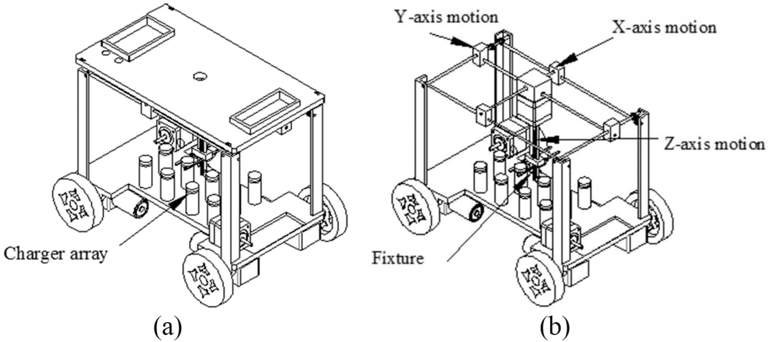
Schematic diagram of the charging vehicle: (a) the moving device and separable charger array and (b) the mechanic fixture with x, y, and z-axis motion capabilities for grasping the charging battery.
Operational model of the proposed charging vehicle in a WRSN
Figure 2 shows a scenario of the proposed new charging model in a WRSN consisting of sensors and chargers with various power states, a charging vehicle with separable charger array, and a base station.
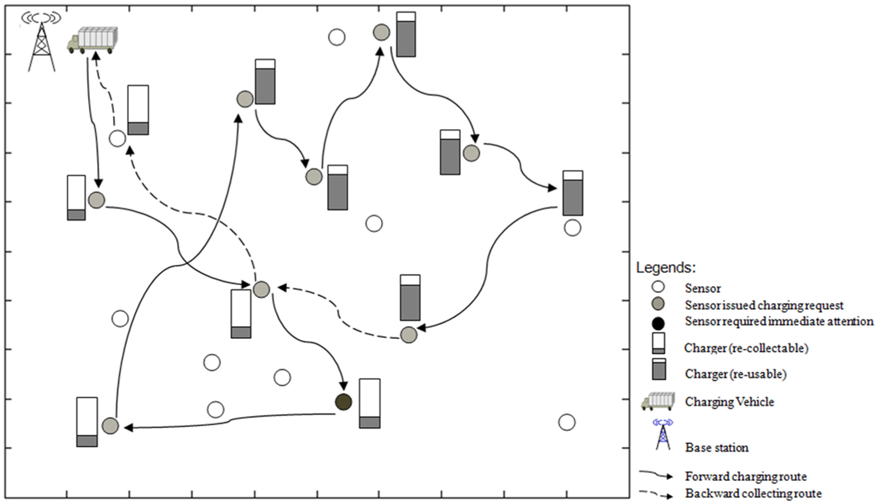
A scenario of the proposed new charging model in a WRSN.
A number of assumptions we made in the proposed new charging model are listed as follows:
There is only one charging vehicle with its initial position at the base station.
The charging vehicle can carry at most m (m > 1) chargers.
The base station has enough spare chargers for all potential charging missions.
A sensor node sends charging request when its power level drops below some pre-defined threshold (Et).
All charging requests from sensors would be successfully relayed through some path to the base station, which then makes a charging schedule for the charging vehicle accordingly. In other words, the charging vehicle is not responsible for data collection as designed in Zhao et al. 10 and Guo et al. 11
All sensors (and the charging vehicle) are equipped with positioning device (such as GPS), so that the charging vehicle can move to the appropriate position of sensors demanding energy.
All sensors and battery cells are also equipped with LED light, which sends light signal to the charging vehicle so that it may calculate the direction and distance of the targets to further guide it to the sensors demanding energy or the battery cells waiting for recollection.
The unloading and loading time of chargers is negligible as compared to the vehicle’s moving time.
The power transfer process begins immediately after the unloading of a charger to a sensor, and the charging vehicle may proceed to the next scheduled node. Also, a charger provides power to only one sensor at a time for power transfer efficiency. No assumption is made as to which kind of wireless charging technologies would be used, although magnetic resonance is favored at this point as it does not require the charging and charged devices located in very close range.
A sensor ceases to operate when its power level drops below some pre-defined threshold (Ed).
Forward charging and backward chargers recollection
According to section “Operational model of the proposed charging vehicle in a WRSN,” the charging vehicle begins its mission from the base station with m chargers on board. We divide the mission into two phases: the forward charging and backward charger recollection phases. The more detailed descriptions of the two procedures are given as follows.
The forward charging phase and its goals
The forward charging phase refers to the charging trip of the charging vehicle from the base station to the last node of a scheduled path given by base station. Specifically, the base station receives the charging request of Nr sensors through various routing mechanisms of the WSN and calculates the charging path according to the proposed REDF algorithm. Charging vehicle then loads m chargers from the base station, starts its trip to each requested sensor and unloads charger according to the scheduled route. The goals are extending the lifetime of the sensor network and shortening the moving distance of the charging vehicle.
The backward charger recollection phase and its goals
The backward charger recollection phase refers to the trip that the charging vehicle returns to the base station upon completing its scheduled forward charging mission. While on the way back, the vehicle may collect chargers to the base station for recharging and fills its charger array again for the next mission. The backward charger recollection phase is not our main focus in the paper. Accordingly, only a simple strategy, in which the charging vehicle collects as many as possible chargers that are within some limited detouring range along its way back to the base station.
In the following, we will present the details of the forward charging process, the REDF algorithm, in section “REDF scheduling algorithm,” and briefly explain the backward charger recollection procedure in section “Backward chargers recollection.”
REDF scheduling algorithm
In this section, we will first show the idea of our proposed revised EDF by demonstrating an example as depicted in Figure 3, followed by detailed descriptions of the corresponding algorithms. Figure 3(a) presents a scenario showing a potential visiting order, which we called a mission, of the charging vehicle as a result of an application of the EDF scheduling. The weight of the directed edge represents the traveling time of the charging vehicle from one sensor node to the other, while x/y beside a sensor node indicates its battery’s remaining time (time the sensor node dies) and the expected arrival time of charging vehicle, respectively. It is clear that in this case of EDF scheduling, three sensors marked with star notation in this scenario would have been dead prior to the arrival of charging vehicle. However, if we also take into consideration the factor in the charging vehicle’s moving time in between nodes (instead of focusing only the urgency in recharging factor, as EDF does) and make appropriate adjustment of visiting sequence, as shown in Figure 3(b), every single sensor node can stay alive as they would all be properly charged in time.

(a) Charging vehicle’s visiting order with EDF scheduling and (b) revised visiting order.
The intuition behind the above example suggests that if a scheduled mission does not meet the deadlines of some requested nodes, its visiting order can be rescheduled by giving higher priority to the possible failed nodes, provided that these arrangements would not result in missing deadline for those affected nodes.
According to previous discussions, we propose a two-step REDF algorithm. The algorithm proceeds by first applying EDF algorithm to schedule the visiting order of the request-for-charging sensors, followed by a rescheduling of the previous EDF output. A number of notations used in the following discussion are listed in Table 1. The EDF and main REDF algorithms are shown in Algorithms 1 and 2, respectively.
Notations and their corresponding meaning.

WSN: wireless sensor network.


The EDF algorithm concerns the urgency of charging requirement and generates a corresponding schedule, which may meet the very basic need of a WRSN. However, it does not take into account the possibility of re-ordering some visiting sequence (provided that this change does not compromise the mission) to shorten the moving distance of the charging vehicle. Accordingly, the idea of our proposed REDF algorithm is to review all the possible permutations of the charging route derived from the EDF algorithm and finds a better visiting order that may further minimize the overall moving distance of the charging vehicle. However, in case the EDF-generated schedule involves a long path that contains many sensors, the number of permutations may increase substantially. As a result, our algorithm adopts the concept of working window, which limits the number of sensors under review to some pre-determined window size, that is, w, without having to process the whole charging route with all Nr sensors. The determination of the size of window will be included in the simulations in section “Simulation results.”
Instead of reorganizing the partial charging route (within the window) unconditional as described above, we may also set some criteria to filter out scenarios that optimization is not required based on route quality. For example, in Figure 4, the charging vehicle moves from base station (BS) to node A, B, C,…, H sequentially and then goes back to BS. Also, the weight of an edge represents the distance between its two end nodes. It is clear that this particular scheduled route is far from optimal. First of all, the angle formed by segments from BS to A and A to B is so sharp that it looks like the vehicle would be virtually moving back and forth, which is a sign of potentially poor scheduled visiting order. Second, the distance between BS and A appears to be a bit longer than the other segments. If, however, an intermediate node (e.g. node C) can be visited with only minor detour along the way to node A (from the BS), the charging tour may be more efficient in terms of overall moving distance. Accordingly, this longer distance of a particular route segment may also be considered as a sign of bad scheduled visiting order.

A scenario illustrating two possible criteria in evaluating charging route quality.
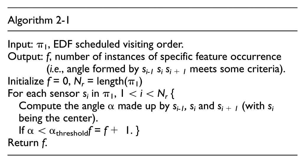
As illustrated above, the collective occurrences of these signs may be used to evaluate the quality of a specific scheduling, and thus to determine whether a rescheduling procedure needs to be initiated. For example, we may consider two occurrences of acute angles or two particular long segments in a scheduled route as acceptable. On the other hand, if it is not the case (i.e. more than two occurrences), the partial rescheduling procedure would be activated. The detailed REDF algorithm is given in Algorithm 2. Note that we denote unconditional partial route rescheduling with no filtering as REDF_NF. Determine whether to perform the partial route rescheduling by considering the occurrences of acute angle, longer distance route segment, or both of the above, are denoted as REDF_A (Algorithm 2-1), REDF_L (Algorithm 2-2), and REDF_AL (Algorithm 2-3), respectively, as shown in Step 4 of Algorithm 2.


The complexity of the revised EDF algorithm (Algorithm 2) is analyzed as follows. Let Nr be the number of sensor nodes that issued charging requests, each of which also corresponds to the path length of EDF scheduled charging route, π1. And, w, as specified earlier, is the pre-determined window size.
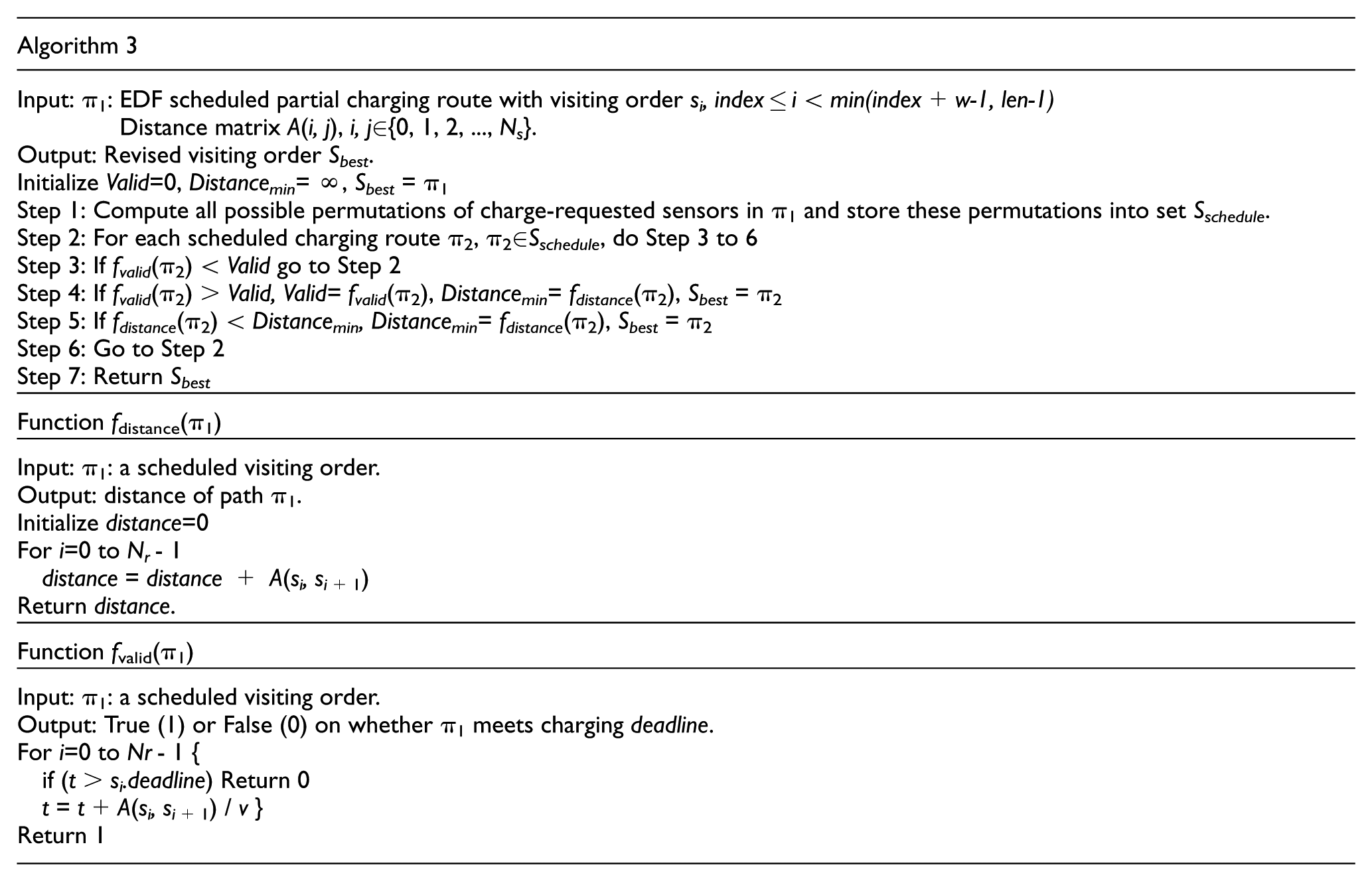
As Algorithm 2 consists of Algorithms 2-1, 2-2, 2-3, and 3, we first show their complexities. Algorithms 2-1, 2-2, and 2-3 are straightforward, each takes O(w) time since the maximal input path length to the above four algorithms is w. Step 1 of Algorithm 3 takes O(w × w!) time in complexity as it needs to compute all visiting order permutations, O(w!), of the input nodes, with each permutation requiring O(w) computational time. Steps 3–6 will be performed in O(w!) time, and the complexities of fdistance and fvalid are both O(w), which also makes it O(w × w!). Accordingly, the overall complexity of Algorithm 3 remains O(w × w!).
Back to Algorithm 2, the EDF algorithm (sorting the charging order of the Nr request-charging sensors) and the computation of distance matrix, A(i, j), takes O(Nr log Nr) and
Backward chargers recollection
On its way back to the base station, the charging vehicle is supposed to collect chargers that have completed their tasks for future use. As our focus of this article is on the forward charging process, here we only propose a very simple and straightforward algorithm for chargers recollection. The algorithm proceeds by first drawing a straight line in between the charging vehicle’s returning position and the base station, as shown in Figure 5. The charging vehicle then collects those chargers that are located within a fixed range, d, along the straight line (circles in dark color). The algorithm is designed such that the charging vehicle would not deviate much from its direct returning path in order to contain the cost of charger re-collection (Algorithm 4). It also allows us to evaluate the approximate number of chargers required at this stage. However, a more complex recollection policy and its effects on the forward charging and number of chargers collected should be assessed in the future.

Illustration of the backward charger recollection algorithm.

Let m be the number of task-completed chargers. Steps 1–3 take O(1), O(m), and O(m log m) time. As a result, the complexity of the backward charger recollection algorithm is O(m log m).
Simulation results
As there is no similar previous work, the main objective of our simulation would be comparing performance between our proposed REDF and the EDF algorithms, and among variations of the REDF algorithms (i.e. REDF_NF, REDF_A, REDF_L, and REDF_AL). In our simulations, we assume that there are Ns (=100) sensors randomly and uniformly distributed in a 600 m × 600 m rectangular region. The base station locates at the center with coordinate (300 m, 300 m). The charging vehicle is set to move at speed v (=10) meter/second. We define the lifetime of a given wireless sensor network (Twsn) being the time between the beginning of network operation and the first dead sensor appears, which will then stop the simulation. Twsn would be one of the main indicator in evaluating the performance of the algorithms in this study. In addition, the number of requests from sensors that are successfully recharged (Nc) and the average moving distance of the charging vehicle (Davg) would also be our metrics in measure the WRSN performance.
It is noted that the busier a WSN is, the more power consumption of its sensors, and thus the more frequent in issuing requests for recharging. In our simulation, we defined three network loading conditions (referred to as heavy, medium, and light) with sensors issuing one charging request every 0–400, 400–800, and 800–1200 s, respectively. In all of the following simulations, 100 charging requests are generated randomly, and all numbers shown are the averages of 10 simulation results.
First of all, we would like to evaluate the appropriate setting of sensors’ power level threshold (Et) that triggers the charging request under the above-mentioned network loading conditions through EDF simulations. Totally nine ranges of Et are defined in this simulation, which are 300 ± 100, 500 ± 100, 700 ± 100,…, and 1900 ± 100, referring to as battery’s remaining time in seconds. The simulation results, as shown in Figure 6, indicate that when Et is set higher than 1500 ± 100 (in between 1400 and 1600 s), more than 50 and up to 95 (out of 100) charge requests can be successfully satisfied (Nc). It also appears that lower Et settings (i.e. less than 900 ± 100) correspond to very poor performance both in lifetime of a WSN (Twsn) and number of successful recharge (Nc). As a result, setting Et to the five ranges center at 1500 ± 100 should be a good choice for evaluating the potential improvement with our proposed REDF algorithm.
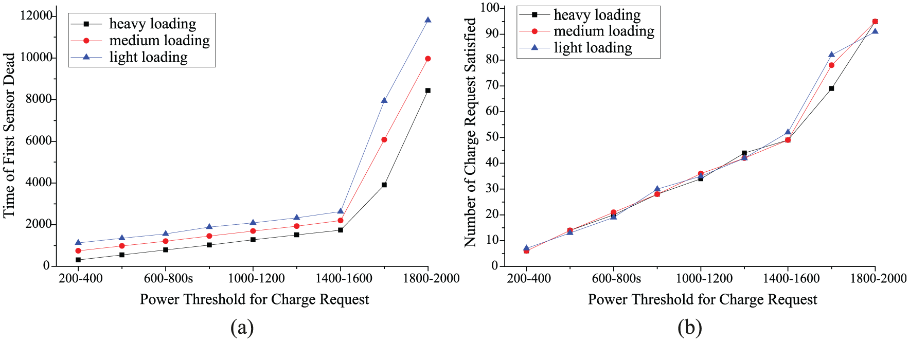
EDF performance on heavy, medium, and light network loadings under various power level settings: (a) time of first sensor dead (in seconds) and (b) number of charge request satisfied.
Next in our simulations, we tried to examine the effect of window size in the case of REDF application (using case of REDF_NF in Algorithm 2). The window size is varied between 3 and 10 with network loading set at medium (one charging request issued every 400–800 s). The results are shown in Figure 7. Note that results with window size equals to 3 and greater than 8 are not shown due to poor performance and excessive computational time. It appears that both good performance and reasonable computation time can be achieved at the same time when w is set to 7, which will also be adopted in subsequent simulations.

Effect of window size (w) on REDF algorithm (REDF_NF of Algorithm 2) under various power level settings: (a) number of charge request satisfied and (b) computation time (in seconds).
In Figure 8, we compare the performance of EDF and REDF (with no filtering, REDF_NF, and window size, w, set to 7) under medium network traffic condition. As we can see, REDF outperforms EDF in almost every performance metric, including lifetime of WSN, number of charge requests satisfied, and average charging distance, while with only roughly 6 s increase in computational time. As a matter of fact, in most cases of this simulation (9 out of 15), REDF does satisfy all the charging requests issued by the sensors. While, on the other hand, the EDF fails to meet all the sensors’ charging demands in every simulation cases. In addition, as shown in Table 2, the REDF achieves that with only a few extra chargers than that of EDF in case all the charging requests are satisfied. Overall, the REDF does perform significant better than EDF with slightly extra cost on the computation time in scheduling and number of chargers used.

Performance comparison between REDF and EDF algorithms on heavy, medium, and light network loadings under various power level settings: (a) WSN lifetime (in seconds), (b) number of charge requests satisfied, (c) average charging distance of vehicle (in meters), and (d) computation time (in seconds).
Number of total chargers used concurrently in various scenarios.

EDF: earliest deadline first; REDF: revised earliest deadline first.
95 (out of 100) charging requests are satisfied.
91 (out of 100) charging requests are satisfied.
In addition, we also evaluate the effects of using filters (Algorithms 2-1, 2-2, and 2-3) in determining whether the partial route rescheduling process (Algorithm 3) should be initiated. The simulation is performed under medium network traffic condition with w and Et set to 7 and 1500 ± 100, respectively. The results are shown in Figure 9. Note that the number of features represents the collective occurrences of some particular sign. For example, when the number of features set at 2, it means that to initiate the partial route optimization, there needs to have at least two occurrences of acute angle instances in the case of REDF_A or two occurrences of longer distance segments (than the average distance) in the case of REDF_L. Accordingly, zero number of feature corresponds to REDF_NR scenario, which indicates the partial route rescheduling would be performed unconditional. According to the results, it appears that using the occurrences of acute angles (REDF_A) or combination of acute angles and long segments (REDF_AL) as the conditions for initiating partial route rescheduling may reduce the computation time, and still maintaining pretty good performance both in WSN lifetime and in fulfilling sensors’ charging needs as compared to the REDF_NF case. However, the average charging distance increases quite sharply if the number of features set higher (above 3) in the case of REDF_A, which is quite as expected as that means charging vehicle was moving back and forth. Overall, it seems to be a good idea in using REDF_AL to avoid frequent activation of route rescheduling in case the computation resource (of base station) is limited.

Performance comparison among REDF with various filtering strategies (REDF_A, REDF_L and REDF_AL) under various feature size settings: (a) WSN lifetime (in seconds), (b) number of charge requests satisfied, (c) average charging distance of vehicle (in meters), and (d) computation time (in seconds).
Finally, the simulation results regarding how the simple backward charger recollection algorithm (with d set to 30) performs is shown in Table 3. Note that the numbers depicted are recollected chargers throughout the whole simulation, instead of just one returning trip. Apparently, there is still much to be done regarding charger recollection algorithm in the future.
Number of recollected chargers in the backward charger recollection phase.
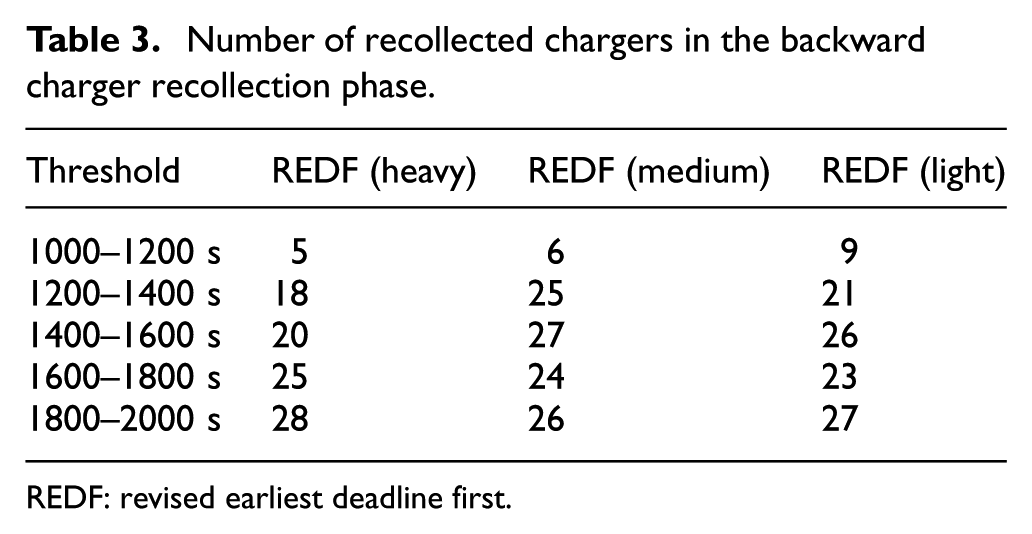
REDF: revised earliest deadline first.
Conclusion and discussion
In this article, we propose a new WRSN model that provides power replenishing using a charging vehicle equipped with separable charger array. The charging vehicle works like the conventional one that is capable of moving around the sensors deployment area. The major difference lies in the separable charger array, which consists of multiple chargers and a mechanic fixture with three-dimensional motion capabilities that may unload chargers to sensors for recharging and collect chargers that have finished their jobs. The fact that charging vehicle in our model needs not to stay on site with the sensor being charged ensures that it works in a much more efficient way than the conventional ones. Corresponding scheduling algorithms, which include forward charging and backward charger recollection, are also proposed to work with this new model. With emphasis focus on the forward charge scheduling, our extensive simulations demonstrated that it can outperform the more straightforward EDF algorithm in almost every aspect that includes mainly (1) meeting the charging need of sensors and thus increase the overall WSN lifetime, and (2) shorten the average moving distance of the charging vehicle so that it may service more sensors in a more efficient way.
However, despite the encouraging perspectives that our proposed model presents, there are still more works to be done. First of all, the recollected chargers with our simple backward charger recollecting algorithm seem to be limited in number. We will be working on more sophisticated algorithms so that chargers can be reused more efficiently in order to reduce the overall number of chargers needed in our model. Second, it appears to us that our simulation conditions may be a bit stricter. Accordingly, exploring more realistic parameters settings that fit more closely to the real-world scenarios in order to investigate the characteristics of the new model will also be our major concern in the future.
Footnotes
Handling Editor: Chang Wu Yu
Declaration of conflicting interests
The author(s) declared no potential conflicts of interest with respect to the research, authorship, and/or publication of this article.
Funding
The author(s) disclosed receipt of the following financial support for the research, authorship, and/or publication of this article: This work is supported by the Top-notch Academic Programs Project of Jiangsu Higher Education Institutions.