
Abstract
Wireless sensor networks are composed of low-energy, small-size, and low-range unattended sensor nodes. Recently, it has been observed that by periodically turning on and off the sensing and communication capabilities of sensor nodes, we can significantly reduce the active time and thus prolong network lifetime. However, this duty cycling may result in high network latency, routing overhead, and neighbor discovery delays due to asynchronous sleep and wake-up scheduling. These limitations call for a countermeasure for duty-cycled wireless sensor networks which should minimize routing information, routing traffic load, and energy consumption. In this article, we propose a lightweight non-increasing delivery-latency interval routing referred as LNDIR. This scheme can discover minimum latency routes at each non-increasing delivery-latency interval instead of each time slot. Simulation experiments demonstrated the validity of this novel approach in minimizing routing information stored at each sensor. Furthermore, this novel routing can also guarantee the minimum delivery latency from each source to the sink. Performance improvements of up to 12-fold and 11-fold are observed in terms of routing traffic load reduction and energy efficiency, respectively, as compared to existing schemes.
Keywords
Introduction
Wireless sensor networks (WSNs) are composed of a large number of unattended sensor nodes. Generally, WSNs are deployed in hostile, hazardous, and inaccessible environments, for example, health, military, home, 1 target tracking, 2 water monitoring, 3 and surveillance. 4 Sensor nodes are often powered by batteries that may not be recharged. Moreover, many sensor network applications are meant to last for a long time. An efficient solution to meet this end is to densely deploy sensor nodes and scheduling to sleep and wake-up duty cycling.5–10 This helps sensor nodes to reduce communication overhead and sensing duty cycles.
The scheduling scheme significantly decreases the number of active nodes, thereby prolonging network lifetime. However, decreasing the number of active nodes may cause the network to be intermittently connected. In sensor networks with such a scheduling mechanism, traditional routing protocols, for example, shortest path routing, may not be able to find routes with low latency. That is a mandatory requirement in many delay sensitive applications, such as, military surveillance, security monitoring, and forest alarms.
The problem of finding optimal routes in terms of delivery, latency, and energy consumption in duty-cycled WSNs has sparked interest as seen in the literature.11–20 However, most of the previous work focused on finding optimal routes at each time slot in a duty cycle, eventually resulting in high routing overhead, especially when the number of time slots is huge. This motivates us to present a new scheme to overcome these challenges.
In this article, we employ the concept of non-increasing delivery-latency interval (NDI), a non-extendable time interval of a node in which delivery latency decreases steadily or remains the same. Furthermore, we propose an NDI-based routing scheme that finds minimum latency routes from sensors to the sink at each NDI instead of at each time slot, therefore guaranteeing minimum delivery-latency routes. This scheme is lightweight due to small routing tables on sensor nodes, reduced traffic overheads, decreased delays, and energy efficiency. The main contributions of our work are as follows:
Minimizing the routing information (i.e. routing table size) stored at each sensor and thus reducing the storage cost.
Significantly reducing the routing traffic load which could support in increasing network quality of service (QoS).
Conserving a large amount of energy per node on routing process to extend network lifetime.
The remainder of this article is organized as follows: “Related work” discusses the related literature review. “Network model and problem formulation” presents a network model, assumptions, and definitions. “Proposed NDI-based routing scheme” describes the proposed scheme. Section “Performance evaluation” gives the simulation environment and results. Finally, conclusions and future directions are outlined at the end of this article.
Related work
Sleep and wake-up scheduling has been exploited to conserve energy 6 which can prolong network lifetime. 21 The scheduling scheme significantly decreases the number of active nodes for a given time unit, thereby prolonging network lifetime. The decrease in the number of active nodes may cause the network to be intermittently connected. In such a network, traditional routing protocols may not be able to find minimum latency routes. The problem of finding optimal routes in terms of delivery latency and energy consumption in duty-cycled WSNs has been studied.11–20,22,23,24 The majority of works find optimal routes at each time slot in a duty cycle. That results in high routing overhead, especially when the number of time slots is large. This motivates the need for new scheme to overcome these limitations.
Beraldi et al. 11 addressed the lowest latency path problem, that is, the characteristics of a path with minimum delay that connects a source node to the sink under random duty cycling nodes. Furthermore, they proposed a forwarding protocol based on biased random walks. The sensor nodes just require local information about neighbors and their next active period to make forwarding decisions. This technique is called lukewarm potato forwarding. Their analytical model and simulation experiments showed that it is possible to reduce path latency without significantly increasing the number of transmissions for message delivery to the destination. Specifically, deviating from the shortest path requires additional transmissions, and hence, higher energy consumption. This shows that reducing latency at the cost of an increased number of transactions is not an energy-efficient solution.
Gu and He 12 presented the concept of dynamic switching-based reliable forwarding (DSRF) that optimizes: (1) expected data delivery ratio, (2) expected communication delay, or (3) expected energy consumption for low-duty-cycled WSNs. DSRF was designed for networks with possibly unreliable communication links and predetermined node communication schedules. It focuses on energy and delay reduction by reducing the number of transmissions. This work presents a wake-up scheduling algorithm with a low computational cost. However, it does not reduce the routing table size and guarantee minimum latency paths.
Gu et al. 13 presented three different approaches to provide a real-time guarantee of communication delay. First, they presented a method for increasing the duty cycle at an individual node. Second, they described a scheme of placement of the sink nodes. Third, they proposed a hybrid approach that showed better balance between cost and efficiency on bounding communication delay. The proposed scheme is global optimal in terms of minimizing the energy consumption for bounding pairwise end-to-end delay. However, this scheme does not reduce routing table size and energy consumption.
Research work
15
addressed the important problem of minimizing average communication latency for the active flows while providing energy efficiency in WSNs. The authors formulated a joint scheduling and routing problem aimed at finding the schedules and routes for current active flows with minimum average latency. By constructing a novel delay graph, the problem can be solved optimally by employing the
Sun and Xu 17 is another closely related work. It proposed and evaluated a delay-aware routing scheme for low-duty-cycled sensor networks. The proposed algorithm organizes the network into a layered structure. The sensor, with packets ready to be sent, dynamically determines a forwarder from multiple potential next-hop sensors in terms of timeliness. This delay-aware scheme is limited since it cannot minimize routing table size and guarantee minimum latency routing from multiple sources to a single sink. It can be found that these related works address the target problem partially while a solution dealing with the aforementioned limitation is required.
Galzarano et al. 25 investigated the influence of the number of deployed nodes on such major network performance metrics as energy consumption, delay, and traffic congestion. In contrast to the commonly used network density, they introduced node concentration and evaluated performance of one of the most popular protocols, ad hoc on-demand distance vector routing (AODV), with respect to this new parameter. Moreover, authors proposed an improvement of AODV, which is based on a node concentration-driving gossiping approach.
Network model and problem formulation
Network model and assumptions
A sensor network is composed of static, homogeneous, and randomly deployed sensor nodes. Each sensor consists of a limited and fixed amount of energy and range. Sensor network lifetime is divided into rounds of equal duration

Time round structure where
This work makes the following assumptions:
A simplex bidirectional communication is assumed, that is, node
The network time is locally synchronized so that a node knows when it should send a packet to its neighbor given a working schedule.12–17 Time synchronization of local clocks can be achieved using an energy-efficient time synchronization protocol (ETSP). 26
Thus, for communications between sensors, we assume that the network has a disk communication model with a given communication range.9–11
For the sake of simplicity, we assume there is only one sink in the network.12–14 All the source nodes report sensing data toward the sink.
Each node has its own working schedule by which the node knows when to wake up and work. We do not consider the case where nodes invite their neighbors to wake up out of their working schedule.12–17
Sensor nodes know the working schedules of their one-hop neighbors. 27 This can be achieved using a setup phase in which all nodes are awake and every node broadcasts its working schedule to its one-hop neighbors.
Problem formulation
Table 1 shows the minimum latency routing table of node
Minimum latency routing table for node


An example for the proposed scheme; dark gray and white rectangles denote working and sleeping periods, respectively.
Basic definitions and lemmas
Before presenting definitions and lemmas, we summarize the notation used in this article in Table 2. The basic definitions, examples, and lemmas help in understanding the proposed method. We use these properties later in driving the three algorithms used in our approach.
Descriptions of notation.

Note 1
Definition 1
Example 1
As shown in Figure 2, we have
Definition 2
If node
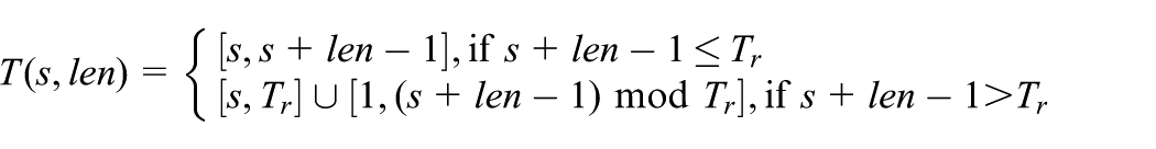
Definition 3
The interval from time
Example 2
As shown in Figure 2,
Note 2
The minimum delivery latency of a link
Definition 4
Delivery latency of node
Property 1
Note 3
Let
Definition 5
Definition 6
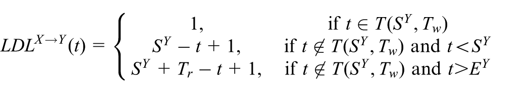
Given a link

An illustration of basic definitions and lemma 1: (a) an illustration of NLDI, (b) NLDIA → B, (c) NLDIA → E, (d), (e) link A → B contains one NLDI, (f) link A → B contains two NLDI, (g) NDIA,B, (h) NDIA,E, and (i) NDIA.
Formally,
For any
Condition (1) infers that link delivery latency decreases steadily or equals to 1; (2) and (3) mean
Example 3
As shown in Figure 3(b) and (c),
Lemma 1
Given a link
Case 1
Assume
Without loss of generality, we can assume
Based on the definition of an
Case 2
Assume

Without loss of generality, we can assume


Since

Let’s consider the interval
From (a) and (b),
Definition 7
Assume node
Formally,
For
where
Condition (1) means link delivery latency decreases steadily or is equal to the minimum latency of this interval (
Example 5
As shown in Figure 3(g) and (h),
Definition 8
An NDI of node
Example 6
As shown in Table 1 and Figure 3(i),
Lemma 2
Assume node A forwards a packet to the sink node S via node B. An
n = 0: there does not exist any
There are three possible cases shown in Figure 4(a)–(c). Since the cases in Figure 4(a) and (b) are very similar and the case in Figure 4(b) is more general, we will focus on the case in Figure 4(b). As shown in Figure 4(b) (refer to Figure 3(e)),

For any
For any
From (1), (2), and (3),

An illustration of basic definitions and lemma 2: (a) one NLDIA → B contains one NDIA,B, (b) one NLDIA → B contains one NDIA,B (general), (c) one NLDIA → B contains one NDIA,B, (d) working schedules, (e) LDLA → B, (f) DLB, one NLDIA → B contains two NDIA,B, (g) one NLDIA → B contains two NDIA,B, (h) one NLDIA → B contains (k + 1) NDIA,B, and (i) property of combined ATS.
n = 1: there is one
From lemma 1,
For
For
From (1), (2), and (3),
The proof is similar to the above case.
n = k: assume lemma 2 holds with
Lemma 2 holds with
Let’s consider the interval
Definition 9
The start time of an
Property 2
Let
Figure 5 shows the routing table formats representing routing information.

Routing table (a: time-slot-based routing and b: NDI-based routing scheme), format of an RAP (c), and routing record table (d: time-slot-based and e: NDI-based routing).
Simple RT’s format of the time-slot-based routing scheme: to determine the minimum latency routes from each sensor to the sink, the
Simple RT’s format of the NDI-based routing scheme: as mentioned in definition 7, we need the delivery latencies at the starting and ending times of each NDI to calculate the delivery latency at any time slot inside this NDI. Therefore, in order to find the minimum latency routes from each sensor to the sink, the
RAP’s format of the time-slot-based and NDI-based routing schemes:
Proposed NDI-based routing scheme
The proposed routing scheme has a small footprint in terms of size of routing tables, amount of energy required by the routing process, traffic load, and creation of minimum latency routes. The lemmas and related properties derived in the previous section are used to formulate the three algorithms used in our scheme.
Overview
The proposed scheme finds minimum latency routes from sensors to the sink at each interval of time instead of at each time slot. Obviously, to minimize the number of intervals to be stored at each sensor, we have to maximize the length of an interval, but we have to guarantee obtaining the minimum latency routes from each sensor to the sink. In this article, we introduce the concept of a NDI: a non-extendable interval of time inside the working interval of a node in which delivery latency decreases steadily or remains the same (refer to definition 7). Using NDI, we can easily obtain the above goal. Therefore, the purpose of the proposed NDI-based routing scheme is to find the list of NDIs and corresponding minimum latency routes to the sink at each sensor.
Algorithm description
Our proposed scheme uses an initialization phase, in which all sensors are awake, to build the
Algorithm 1
Processing

Pseudocode of the RAP-processing algorithm.
Algorithm 2
Building

Pseudocode of the RT-building algorithm.
Algorithm 3
Updating
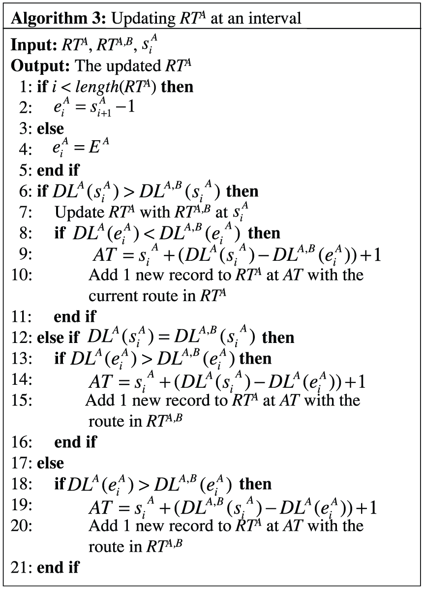
Pseudocode of the RT-updating algorithm.

An illustration for algorithm 3: (a) lines 6–11, (b) lines 12–16, and (c) lines 17–21.
Algorithm walk-through
We use the example in Figure 2 to illustrate the walk-through of the proposed NDI-based routing scheme. For the sake of simplicity, we describe the routing process in four steps: (1)
Routing advertisement packets summary of node X.

DL: delivery latency.
Routing table summary of
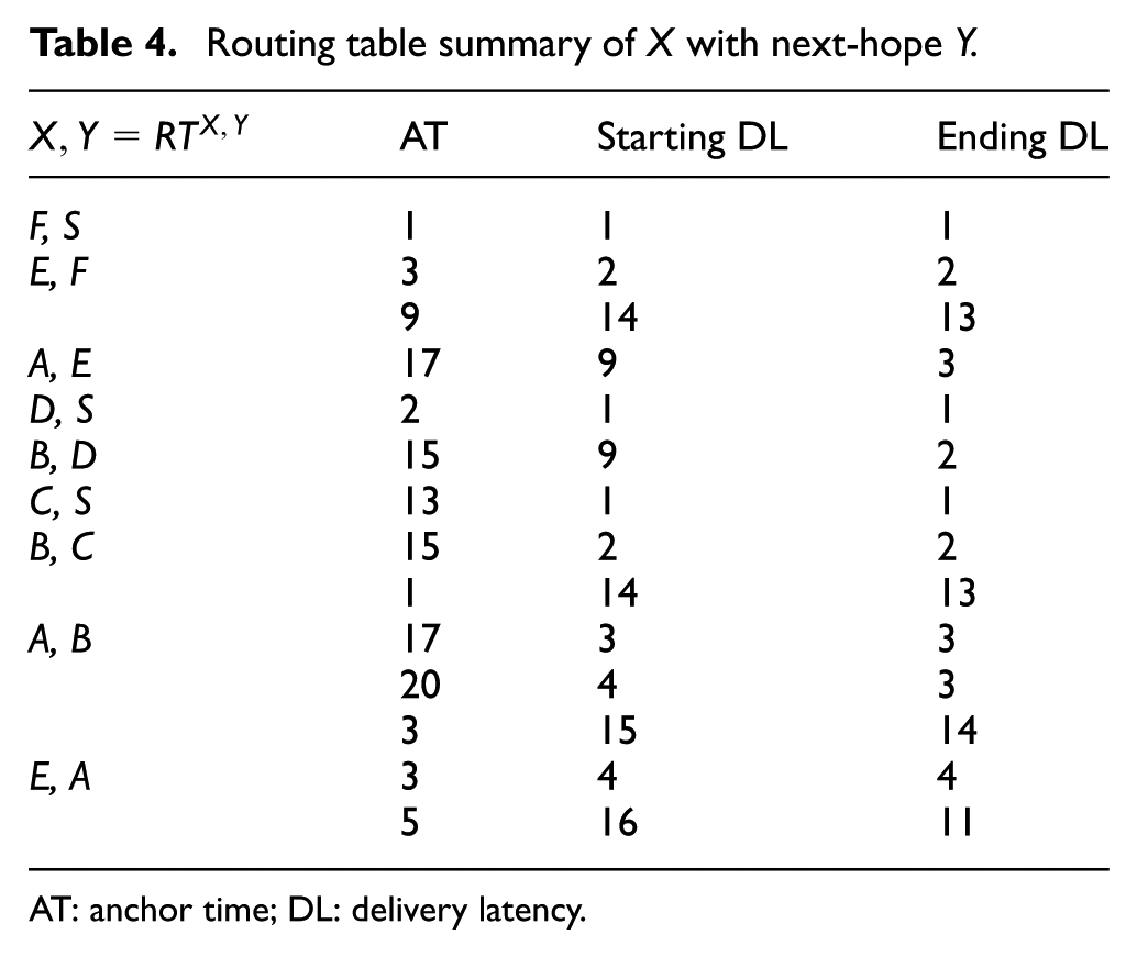
AT: anchor time; DL: delivery latency.
Node
Routing table summary of node

AT: anchor time; DL: delivery latency.
Node
Final routing summary after comparison.
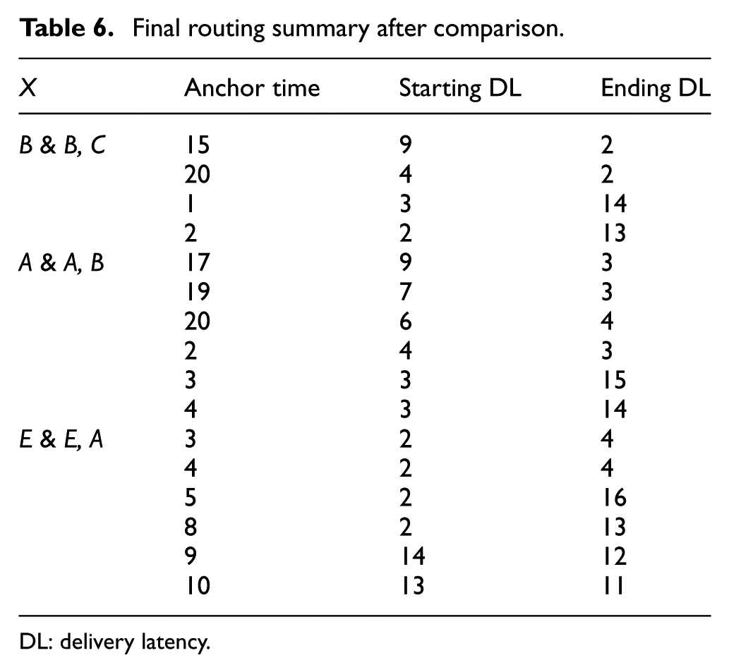
DL: delivery latency.
Node
Thus, node
Performance evaluation
In this simulation study, we employ a custom built simulator in Java to evaluate the performance of the proposed scheme, NDI-based routing, under different network sizes, duty cycles, node densities, and lengths of time round. We compare the proposed scheme with the time-slot-based routing scheme. 23 The time-slot-based routing scheme is implemented exactly the same as the proposed NDI-based routing scheme, but finds the minimum latency routes from sensors to the sink at each time slot. We used the following three metrics to evaluate the performance:
The size of routing tables. The average number of bytes stored at each sensor for the routing purpose.
Routing traffic load. The amount of traffic transmitted during the routing process.
Energy consumption per node. The average amount of energy consumed by each sensor to obtain the minimum latency routing table.
Note that the proposed NDI-based routing scheme guarantees obtaining the minimum latency routes from sensors to the sink, and the performance of the NDI-based routing scheme is exactly the same as the flooding scheme. Therefore, we do not show the performance result in terms of delivery latency.
Simulation environment
Sensor nodes are randomly deployed and each node randomly selects the starting time of its working interval. The working interval
Different network sizes. The number of nodes increases from 200 to 1000 and the deployed area increases proportionally from
Different duty cycles. The node duty cycle increases from 10% to 50%.
Different node densities. The node density increases from 6 to 12.
Different lengths of time round. The time round increases from 100 to 500.
Simulation parameters.

PHY: physical; MAC: media access control; NDI: non-increasing delivery-latency interval.
For each setting of network sizes, duty cycles, node densities, and lengths of time round, a simulation is run 100 times and we average them to get the mean value with 95% confidence.
Simulation experiments results
In this section, performance measure of the proposed scheme is compared with existing schemes.
The size of routing tables
As mentioned in the previous sections, the proposed NDI-based routing scheme minimizes the routing information stored at each sensor. As shown in Figure 10, the NDI-based routing scheme significantly improves the performance of the time-slot-based routing scheme in terms of the routing table’s size. Note that in the case of the NDI-based routing scheme, we obtained the mean (Mean of max NDI-based routing) and the maximum (Max of max NDI-based routing) of the maximum routing table’s size of sensor node in each run.

The size of routing tables: (a) network size, (b) duty cycle, (c) node density, and (d) length of time round.
For example, as shown in Figure 10(d), when the
Routing traffic load
Since the proposed NDI-based routing scheme minimizes the size of a routing table, it significantly reduces the routing traffic load in the network, as shown in Figure 11. For example, as shown in Figure 11(a), when the number of nodes is 1000, the traffic load of NDI-based and time-slot-based routing are 5326.88 and 64,896.31 kilobytes, respectively. That is, the NDI-based routing improves the performance of the time-slot-based routing is 12.18-fold.
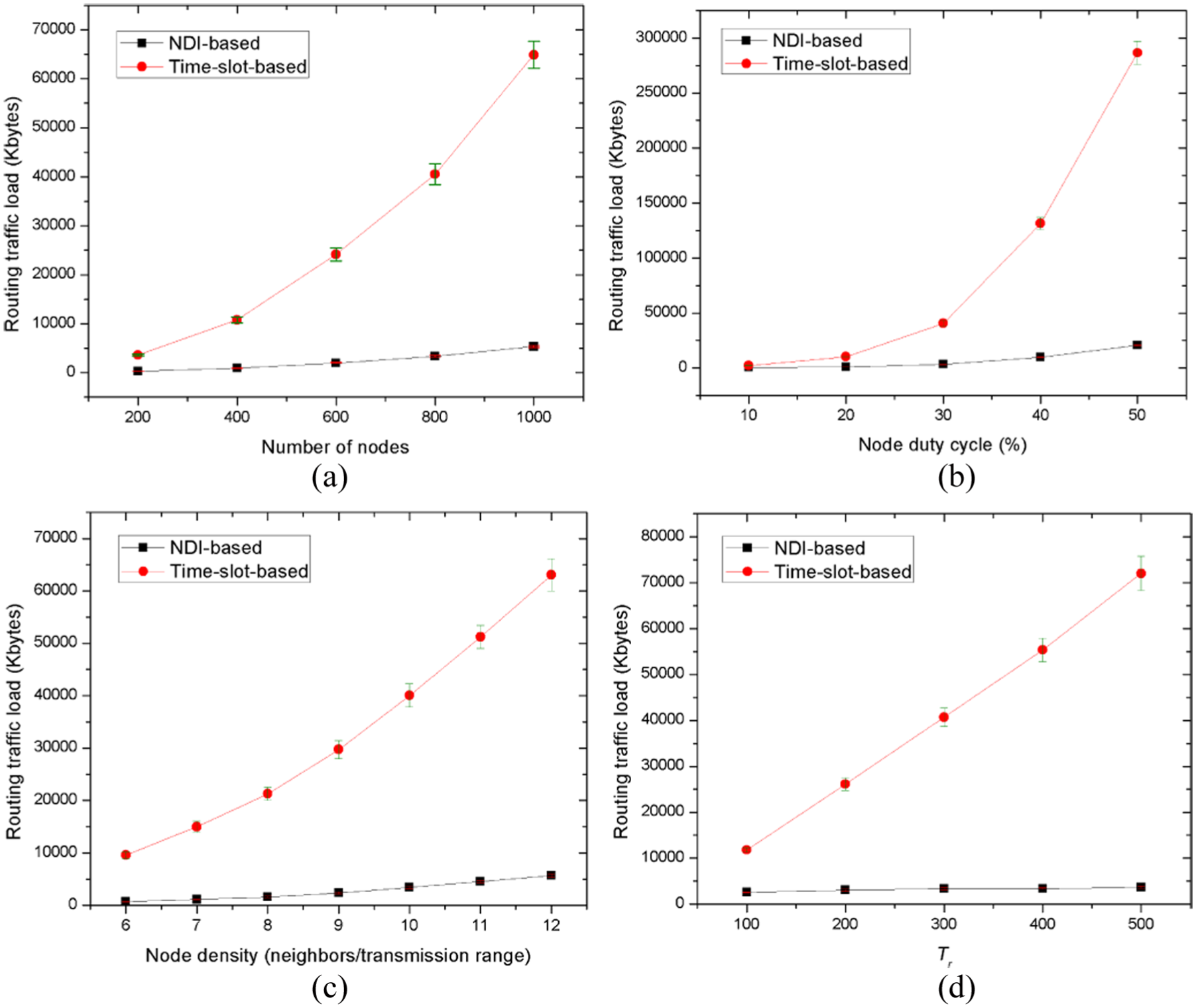
Routing traffic load: (a) network size, (b) duty cycle, (c) node density, and (d) length of time round.
Energy consumption per node
Due to the reduction of the routing traffic load, the proposed NDI-based routing scheme helps sensors conserve a large amount of energy consumed in the routing process, as shown in Figure 12. For example, as shown in Figure 12(c), when node density is 12 neighbors/transmission range, the energy consumption per node of NDI-based and time-slot-based routing are 187.21 and 2099.11 mJ, respectively. It means NDI-based routing improves the time-slot-based performance is 11.21-fold.

Energy consumption per node: (a) network size, (b) duty cycle, (c) node density, and (d) length of time round.
Conclusion
Finding routes with low delivery latency in sleep- and awake-scheduled WSNs is a mandatory requirement in many critical applications. The majority of recent schemes find the optimal routes at each time slot, thereby resulting in very high routing overhead. In this article, we proposed the concept of an NDI and proposed the NDI-based routing scheme that finds minimum latency routes from sensors to the sink at each NDI instead of each time slot.
Analysis and simulation results showed that the proposed NDI-based routing scheme minimizes the routing information stored at each sensor and significantly improves the performance of the time-slot-based routing scheme in terms of routing traffic load and energy consumption. Furthermore, it also guarantees the minimum delivery-latency routes from the sensors to the sink. In this work, we assume the network has a disk communication model with a given communication range. We will consider the lossy environment in our future work. Furthermore, we will consider the multiple-sink-based network scenario to test our proposed scheme.
Future work
In this article, we have presented our NDI-based routing scheme and validated it using extensive modeling, simulation experiments, and significant performance improvements. Several additional WSN aspects and scenarios in our approach can lead to interesting future work. One direction can be hardware implementation as a next logical step. Another way forward is to consider addition and/or eviction of the sensor nodes. Considering the cost of time synchronization in terms of exchanged messages would also be an important aspect to consider. One more challenging issue for future research is to adopt the proposed idea for a scenario with a random wake-up interval. Last but not least, a multiple-sink-based WSN scenario is also an interesting future extension of our proposed method. Moreover, we intend to investigate the possibility of an extension of the proposed scheme for using in an Internet of things (IoT) scenario, such as Smart Cities, where a WSN can be considered as a building block for an area sensor network. 29
Footnotes
Handling Editor: Zhong Shen
Declaration of conflicting interests
The author(s) declared no potential conflicts of interest with respect to the research, authorship, and/or publication of this article.
Funding
The author(s) disclosed receipt of the following financial support for the research, authorship, and/or publication of this article: This research was supported, in part, by Korean government, under G-ITRC (IITP-2018-2015-0-00742), ICT R&D (B0101-15-1366, IITP), Priority Research Centers (NRF-2010-0020210), and Basic Science Research Program (NRF-2016R1D1A1B03934615).