
Abstract
Tunnels and subway blast doors are effective barriers to terrorist attacks and emergencies, and research into the mechanical properties of blast doors under explosive dynamic loads can improve and enhance the performance thereof. In this article, surface strain measurements on subway blast door models under dynamic load are carried out using quasi-distributed fibre Bragg grating sensors. The principle underpinning fibre Bragg grating sensing is introduced before the experiment. In the experiment, a model of an explosion-proof door was designed, and the experimental foundation pit was designed to be used to fix the explosion-proof door. Then, eight fibre Bragg grating sensors are placed at different positions on the surface of the explosion door to measure the strain at the time of explosion. Through the experiment we found that the optical fibre grating sensing system can be used under explosive loading surface strain: the strain distribution on the surface of the protective door is revealed under large dynamic strain. At the same time, the rebound effect of the protective door in the explosion was found through the strain phenomenon in double peak phenomenon. The strain distribution and rebound effect in the test results can provide a useful reference for the mechanical design of the blasting door and the strain monitoring of reinforced concrete structures under dynamic load.
Introduction
Currently, the scope of terrorist attacks is expanding, and explosives are commonly used in terrorist attacks.1–3 As subway tunnels are usually in confined spaces and bear a large flow of people, they have become a target for explosive attacks.4,5 Blast doors are the most important protection and partitioning equipment in the subway which are capable of isolating the explosion from further spreading to the crowd. Reinforced concrete blast doors are a common type, while most studies focus on the structural design of the blast door and the ultimate anti-explosive performance.6–10 Due to electromagnetic interference and the destructive effects of an explosion,11,12 there are usually more qualitative studies of explosions rather than a quantitative research, such as by means of finite element analysis for the blast resistance of a door structure.6–16 This article will focus on the monitoring and evaluation of the surface strain on the blast door caused by an explosive shock wave.
In general engineering applications, strain gauges are widely used for measurement of the deformation characteristics of reinforced concrete structures,17–20 but these sensors suffer disadvantages of low precision and poor resistance to electromagnetic interference.21,22 Unfortunately, there is a large instantaneous electromagnetic field generated in this explosion test, so resistance strain gauges cannot be used. Fibre Bragg grating (FBG) sensors have been widely used in deformation monitoring in recent years, with high precision and anti-electromagnetic interference advantages.23,24 If FBG sensors are bonded on a composite blast door, any change in strain on the blast door is reflected by the FBG sensor: as a result, strain measurement by FBG sensors reflects the strain on the blast door if the strain transfer coefficient is known.
For strain measurement with FBG sensors, scholars have conducted static test studies. Lau et al.25,26 compared bare FBG sensors and the theoretical element method on fibre-reinforced polymer (FRP) strengthened concrete beams, and the results showed that FBG sensors can be confidently used given sufficient bond length. Kesavan et al. 27 constructed FBG sensors for interfacial strain measurement on reinforced concrete beams strengthened with carbon fibre–reinforced polymer (CFRP), in which the initiation and propagation of debonding of CFRP was found. Almubaied et al. 28 presented experimental studies on corrosion monitoring by FBG sensors and found a correlation between the FBG wavelength shift and corrosion of the reinforcement. Kang et al. 29 used 20 FBG sensors to monitor the strain in a filament-wound composite tank. Allen et al. 30 studied strain measurement with FBG sensors for investigation of crack propagation and found that strain patterns and crack positions showed a good correlation with relative errors below 10%. In summary, the application of FBG sensors in static strain measurement has been studied widely. These methods and conclusions can provide some reference for dynamic strain measurement; however, compared with static measurement, studies of dynamic strain measurement using FBG sensors remain sparse. Internal strain measurement under dynamic load was carried out using FBG sensors and the experimental results show that the modal analysis of shock and vibration is consistent with the numerical model. 31 Some FBG sensors have been tentatively applied to targets that generate high-speed strains, such as gun barrel, and the results show that FBG can accurately measure the strain in harsh environments of strong electromagnetic radiation. 32 Ayers et al. 33 present a study using FBG sensors under high-strain-rate loading in a Hopkinson bar experiment, in which one-dimensional (1D) and two-dimensional (2D) strain measurements were carried out, and the viability of these sensors under more complex dynamic loading was evaluated. This article describes dynamic strain measurement under explosive load on a special subway door.
This article is organised as follows: section ‘Principle of FBG sensing’ describes the principle of FBG sensing; section ‘Dynamic strain measurement test on a blast door’ details the construction of the design of concrete structure model, the explosion test and the structure of the quasi-distributed FBG sensing system; the experimental results and analysis of sensor data are presented in section ‘Results and analysis’; and finally, conclusions are drawn in section ‘Conclusion and discussion’.
Principle of FBG sensing
An FBG is a passive optical component, which is one of the most widely used optical fibre sensors. This sensor can change the wavelength of the reflected light wave according to the change in temperature or strain. The basic principle of strain sensing using an FBG sensor is shown in Figure 1.
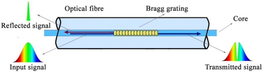
Workings of an FBG sensor.
When a beam of light hits an FBG, each segment of the fibre will only reflect a specific wavelength of light, the wavelength is called the Bragg wavelength after the refractive index is changed, as in equation (1). The wavelength of the signal reflected by Bragg grating is given as34,35

where
The relationship between the reflected wavelength

where
Dynamic strain measurement test on a blast door
Concrete structure model
Two circular reinforced concrete blast door models were designed and used in these experiments: they had a radius of 1.5 m and a thickness of 1 m. The two models are made of concrete (grade C40 and steel bars, grade HRB335; Figure 2). Figure 2(a)–(c) shows the geometric design of the model, the front view of the model and a side view of the model, respectively.
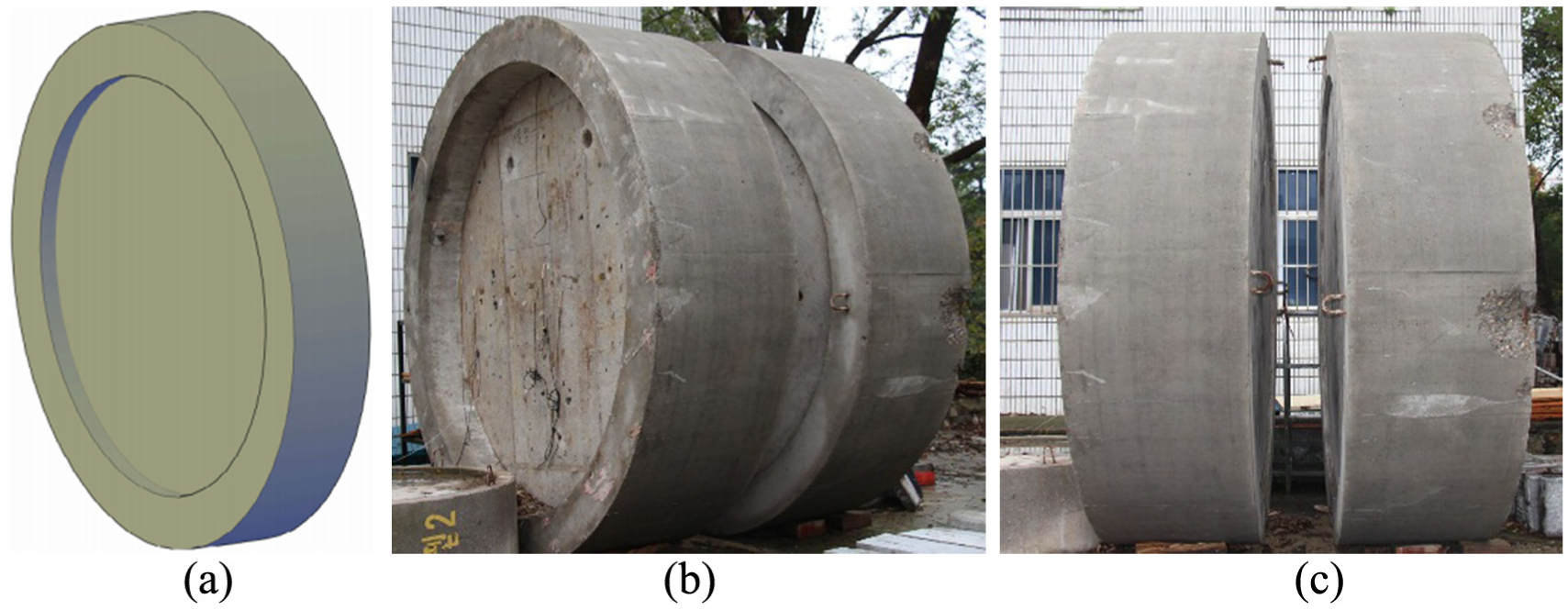
Structure of reinforced concrete model: (a) geometric design, (b) front view and (c) side view.
The experimental set-up in the article was aimed at simulating the effects of an explosion in the tunnel. In the explosion test, the reinforced concrete model was first placed in a prefabricated foundation pit and then a sand surround was installed. After that, the detonating cord is placed in the cavity between the two models (Figure 3). In the explosion test, the physical and chemical reactions of explosives at high temperature and high pressure compress the surrounding air to form a shock wave so that, when the surface of the shock wave arrives at reinforced concrete models, it will instantly deform the outer surface of the models. The authors attempted to install quasi-distributed FBG sensors outside the model to measure and evaluate the deformation of the model during the explosion test.

Position of reinforced concrete model for explosion testing: (a) geometric design and (b) as-installed.
The structure of the quasi-distributed FBG sensing system
For surface strain measurement on the reinforced concrete model subjected to explosion testing, the authors design a quasi-distributed FBG strain measurement system, which consists of the following three parts:
The quasi-distributed sensor. Eight different centre-wavelength FBG sensors are connected in series by fibres to form a quasi-distributed sensor. US-made SMF-28C FBG sensors were used in the experiment and their data were processed by UV laser engraving technology. The effective reflectivity is more than 90%.
Fibre grating demodulator. The fibre grating dynamic demodulator SM130-700 is designed and produced by Micro Optics Co., and uses 16-channel synchronous 2 kHz sampling (Table 1).
Data acquisition and processing server. We installed Micro Optics software on a computer and collected, processed and synthesised all sensor strain data. The quasi-distributed FBG strain measurement system is shown in Figure 4.
Parameters of SM130-700 dynamic fibre grating demodulator.


The quasi-distributed FBG measurement system.
Due to the uneven distribution of the material in the reinforced concrete model and the effect of the steel structure, the distribution of surface strain may be unique. To measure the surface strain on the model under the impact of the explosion more accurately, the gauge distance of the FBG is set to 8 mm, which is used to obtain the mean strain value of the model to reduce the influence of singularity. The FBG sensor is fixed as shown in Figure 5(a), in a cross-symmetrical distribution, along the radial direction at 0.5 m intervals, and then all the sensors were mounted in series to allow quasi-distributed measurement.
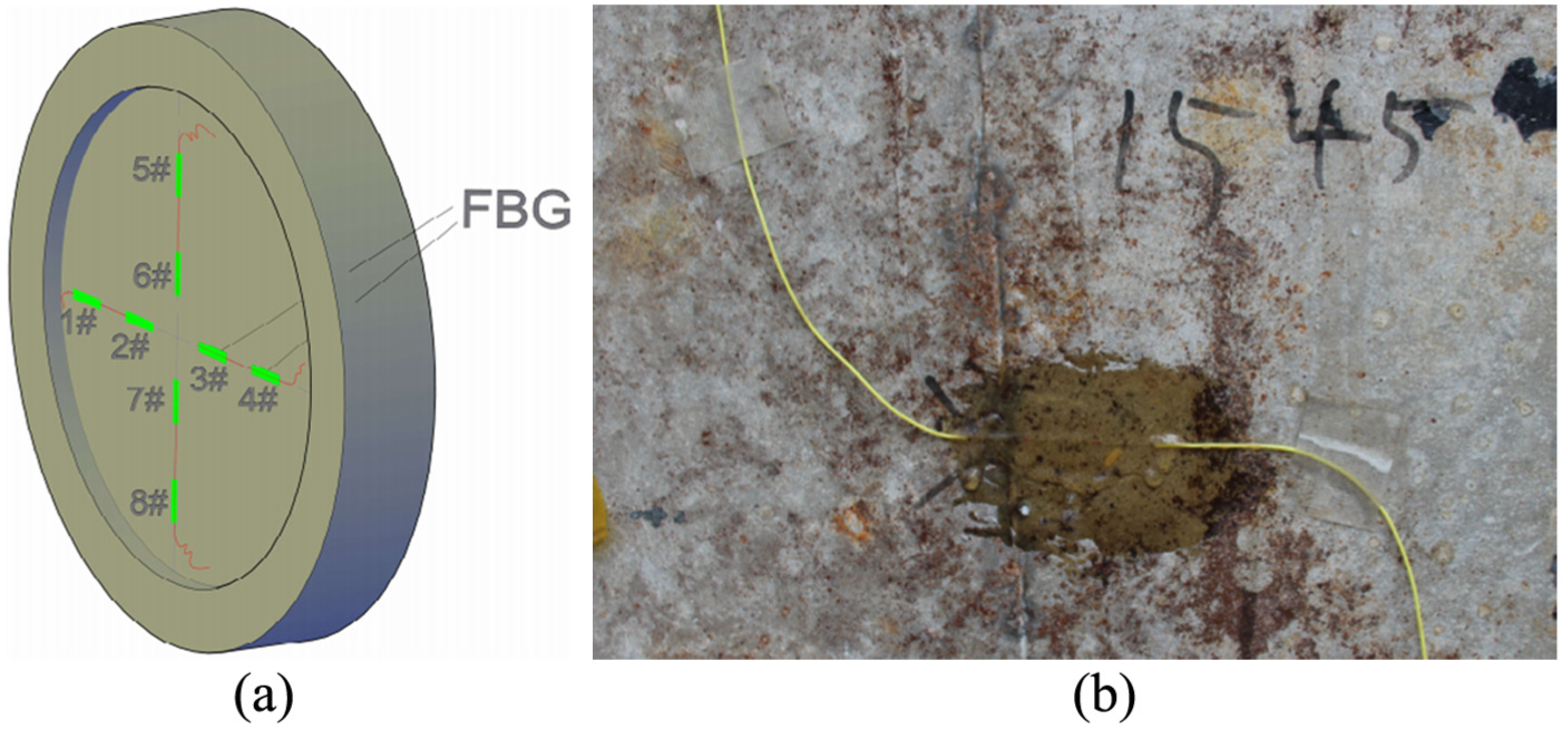
Sensor locations and installation: (a) sensor locations and (b) sensor installation and protection.
To measure the surface strain, FBG sensors were fixed as follows (Figure 5(b)):
Step 1. The rough surface of the model is decontaminated, cleaned and then the fine pores of the model surface are filled with epoxy glue.
Step 2. The fibre grating is pre-tensioned and uniformly cured with epoxy glue.
Step 3. To prevent the fibre from being damaged during the test, we used a jacket to protect the bare fibre leads in the FBG sensors.
Results and analysis
The dynamic response on the blast door under the explosion condition is complicated and it is difficult to express it with a theoretical model. Therefore, it is ideal to carry out a field explosion test. In the experiment, the surface strain of the blast door during the explosion was measured using a quasi-distributed FBG strain sensing system. The strains are calculated using formulae (1) and (2) in section ‘Principle of FBG sensing’; the strain transfer coefficient is not considered in this article due to the high strain-transmission ratio of the bare fibres, which is typically greater than 0.98. The layout of the eight FBG sensors used in the experiment is described in detail in the previous section. In this experiment, all sensors measured the blast door strain data at the time of the explosion.
First, four horizontal FBG sensors are analysed: the peak values of explosion strain measured by four horizontal FBG sensors are between 40 and 80 με (Figure 6). Sensors #1 and #4 (Figure 6(a) and (d)) show lower strains than sensors #2 and #3 (Figure 6(b) and (c)), which is due to the proximity of sensors #2 and 3# to the centre of the explosion. All of the strain peaks are positive, which is due to the expansion of the blast door.

The four horizontal FBG sensors: (a) sensor #1, (b) sensor #2, (c) sensor #3 and (d) sensor #4.
Second, the four vertical FBG sensor data are analysed: differing from the horizontal direction, there are positive and negative peaks in the vertical direction at the moment of the explosion, in which the positive peak range is between 50 and 100 με and the negative peak is above 100 με (Figure 7). Sensors #5 and #8 (Figure 7(a) and (d)) recorded values less than those at #6 and #7 (Figure 7(b) and (c)), which is because the two are far from the centre of the explosion. Analysis of the positive and negative peaks follows below.

The four vertical FBG sensors: (a) sensor #5, (b) sensor #6, (c) sensor #7 and (d) sensor #8.
In sensors 2, 3, 5 and 7, we also observed a significant strain from the rebound vibration (Figure 7). The reason may be due to the sand between the model and the experimental pit being soft; there is a certain pore volume, which due to the explosive load allows the model a certain displacement and collision with the experimental pit follows. In sensors 6 and 8, we found positive and negative staggered high-frequency vibrations (Figure 8): we initially inferred that the collision may be due to non-uniform strain.
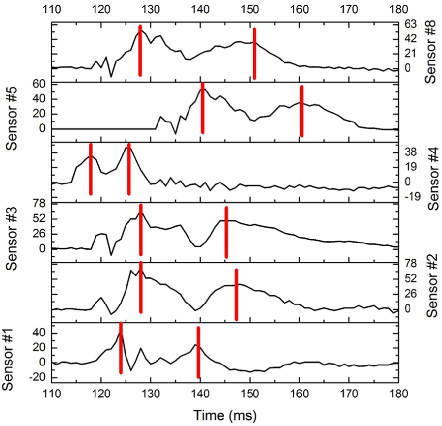
Strain vibration response: sensors 1–5 and 8.
By further analysing the strain values at the time of the explosion, we found that six of the eight FBG sensors had a double positive peak, while the remaining two sensors had positive and negative peaks. Among them, the double positive peak sensors occurred at all four horizontal sensors (1–4) and at two vertical sensors (5 and 8). Figure 8 shows the double positive peaks at six sensors, from which we find that there is a certain difference between the time to first peak occurrence, the earliest occurrence at sensor 4 and the latest occurrence at sensor 5. We also found that the time interval between the two peaks was different, the sensor #4 time interval is shorter (within 10 ms) and the remaining sensors had a time lag of about 20 ms. Overall, the double positive peak time is monitored between 10 and 20 ms and reflects the very pronounced rebound effect of the explosive load measured by these sensors.
In Figure 9, the strains measured at sensors 6 and 7 are shown, which are significantly different from the other sensors. In both the sensors, in addition to the presence of a positive peak, there is a clear negative peak: negative peak values exceed the positive peak values. This proves that the location of the deep explosion sensors 6 and 7, except under outwards expansion, encountered the constraints of the test foundation pit, a clear rebound occurred and negative deformation (inward compression) occurred at the moment of rebound. Therefore, we conclude that the entire protective gate underwent elastic deformation at the time of explosion and the deformation was not uniform. Due to the presence of the experimental foundation pit, internal compression occurred near the edge of the foundation pit.

Strain vibration response of sensors 6 and 7.
Table 2 summarises the test results for all the sensors: in all, eight FBG sensors monitored the results; the maximum strain in the positive direction is 97.53, the maximum strain in the negative direction is −116.20, the average maximum strain is −7.53 and the standard deviation of the largest set of data is 11.22, of which, three indicators were concentrated at sensor 7, making it the most critical.
Statistical analysis of the measured results.

FBG: fibre Bragg grating; SD: standard deviation.
Conclusion and discussion
A quasi-distributed FBG sensing system is used to measure the surface strain at the moment of explosion for a reinforced concrete model of a subway blast door. In the course of the explosion, the eight sensors measured strain values which reflected the instantaneous strain and rebound effect on the blast door. Through analysis of the monitored results, the following conclusions are drawn:
Eight FBG sensors were placed in different positions on the blast door model and eight sets of data were measured in the explosion test. Analysis of these monitoring data showed that almost all FBGs measured the first shock wave caused by the explosion and were essentially consistent with regard to the arrival time and the order of magnitude of the strain pulses. Therefore, it is feasible to measure the strain on the model surface under explosive loading in the presence of strong electromagnetic interference and transient strain. A quasi-distributed FBG sensing system is used to measure the surface strain under explosive loading.
Strains measured by sensors 1, 4, 5 and 8 are significantly smaller than those measured by sensors 2, 3, 6 and 7: this is because the closer the explosion, the greater the strain. Therefore, in the structural design of a subway explosion-proof door, the location of large explosions should be considered and reinforcement should be increased at this location.
The double-peak phenomenon in FBG sensors 1–8 confirmed the existence of a rebound in the explosion, while different measured differences also reflect the influence of the shock wave and the strain patterns are complicated. In the design of a blast door, to prevent positive and negative peak damage to the blast door, it is necessary to strengthen the area around the blast door in the presence of constraints.
Through the experimental work, quasi-distributed FBG sensing technology can provide a new, reliable method of explosion-response measurement. The results can provide a reference for the response of a blast door under explosive load.
Footnotes
Handling Editor: Zedong Wu
Declaration of conflicting interests
The author(s) declared no potential conflicts of interest with respect to the research, authorship, and/or publication of this article.
Funding
The author(s) disclosed receipt of the following financial support for the research, authorship, and/or publication of this article: This work was carried out with funding from The National Natural Science Foundation of China (41604024 and 51609129), China Postdoctoral Science Foundation (Grant nos 2017M611816 and 2016M601815), Beijing Key Laboratory of Urban Spatial Information Engineering (Grant No. 2017210), The State Key Laboratory of Geo-information Engineering (SKLGIE2016-Z-1-3), Shandong Provincial Natural Science Foundation, China (Grant No. ZR2014EEQ002), and Shandong postdoctoral innovation project special Foundation (Grant No. 201502025) and The Fundamental Research Funds of Shandong University.