
Abstract
In wireless multihop bidirectional communication environment, there is a possibility that packet collision and retransmission owing to the hidden node problem decrease efficiency of throughput. The aim of this article is to achieve efficient and reliable packet transmissions in such environments. To do so, we propose a packet transmission scheme named inter-flow network coding with passive acknowledgment. In inter-flow network coding with passive acknowledgment, it is necessary to optimize the encoding latency and to avoid passive acknowledgment packet collision, so we address these issues in this article. Finally, we also confirm that the inter-flow network coding with passive acknowledgment scheme is effective in terms of the collection ratio and delay through simulations.
Keywords
Introduction
In a multihop wireless local area network (LAN) or a wireless sensor network, packets are transmitted from the source node to the destination node by relay from one wireless station (node) to another or “multihop transmission.” The advantages of wireless multihop transmission are that it allows the transmission to a node which cannot be directly reached from the source node and that it does not require base stations or other transmission infrastructure. This is why it is being considered for use over a wide variety of applications, including smart meters, structure monitoring, and disaster response. Market-ready systems are being prepared on the basis of countless R&D efforts and validation tests. Among these applications are, for example, the disaster response system1,2 based on a wireless sensor network described in section “Evaluation of practical applications by simulation,” in which data packets are directed from the sensing nodes to multiple data collection nodes (sinks). This system contains sensors and actuators and collects sensing data from the nodes and transmits signals to operate actuators. Thus, its paths are quite busy with traffic in both directions.
However, in a multihop wireless network based on IEEE 802.11 standard 3 for wireless LANs or IEEE 802.15.4 standard 4 for wireless sensor networks, a flow of traffic in both directions over the paths may degrade throughput due to the hidden node problem. 5 In medium access control (MAC) of these standards, carrier sense multiple access with collision avoidance (CSMA/CA) is employed. Under CSMA, since any transmitting stations outside carrier sense range do not detect packet transmissions by other stations, it is possible for any one such station to transmit regardless of the fact that another station is already in the process of transmission. This causes packet collision and is called “the hidden node problem”; the colliding packets must be retransmitted, and this drastically slows throughput as a result. One of the ways to mitigate this problem is to reduce the number of packet transmissions.
“Network coding” (NC) 6 is expected to reduce the number of packet transmissions. A form of NC in which packets in different network flows are encoded by relay nodes is called inter-flow network coding (IFNC).7,8 In this article, with the objective of enabling highly efficient and reliable packet transmission in bidirectional communication environments, a scheme referred to as IFNC with passive acknowledgment (IFNCPA) is proposed here; this scheme is a packet transfer protocol combining IFNC and passive ACK. 9 This article combines the information of two previous technical reports10,11 with the results of an evaluation of the new capabilities under the proposed scheme to demonstrate that the proposed scheme improves the transmission and efficiency.
As described in section “Preparations and issues,” when packets encoded using IFNC are broadcasted to neighboring nodes (the next-hop nodes), if the broadcast packets are not accurately received, there is no way for the transmitting node to “know” that because a broadcast packet is not usually acknowledged. Since the packets are not retransmitted, the transmission reliability is degraded. The transmission simulation results described in section “Parameter tuning and basic evaluation” also support this, showing that during sequential unicast transmission of packets under only IFNC, the collection ratio is lower than under multihop transmission.
COPE 12 is known as the first practical implementation for wireless mesh networks. COPE is located between the MAC layer and the Internet Protocol (IP) layer. COPE header is inserted between the IP header and the MAC header. By including ACK blocks in the COPE header, an adjacent node is notified of reception of the encoded packet. BEND 13 incorporates the function of IFNC into the MAC layer of IEEE 802.11. For the sake of this, the IEEE 802.11 MAC header needs to be modified. In BEND, a modified ACK frame is sent to notify of reception of the encoded packet. These ACK mechanisms for encoded packets lead to overhead. Several variants of COPE and BEND have been proposed to enable more coding opportunities and increase network capacity, for example, DCAR, 14 CORE, 15 DODEX+, 16 INCP, 17 and FlexONC. 18 These schemes can be regarded as inheriting the ACK mechanism of COPE and BEND, and none of them utilizes passive ACKs.
Dualcast transmission 19 is another approach for the exchange of ACK packets rather than the multicast transmission in order to compensate for degradation in reliability in IFNC. It is no easy matter to extend the MAC layer, which must be done for dualcast transmission, making it difficult for practical application. In contrast, employing passive ACK, which provides confirmation by monitoring packet relay by the next-hop node, the IFNCPA scheme attempts to compensate for the reduction in reliability in broadcast transmission, with no necessity to extend the MAC layer at all.
As explained in section “Preparations and issues,” IFNC inherently has the function of implicit passive ACK for encoded packets, which is not fully utilized in the previous studies. In IFNCPA, passive ACK is also applied to native packets, that is, unencoded packets. This IFNCPA scheme is not merely a combination of IFNC and passive ACK. As section “Preparations and issues” will show, the encoding latency must be set to the proper interval, and the issue of collision of passive ACK packets must be avoided. Therefore, a combination of systems is examined in this study. One system determines the encoding latency dynamically using the intervals between arriving packets from previous counterflow data, and the other avoids passive ACK packet collision by determining the best offset for the shifts the timing of transmission of one or the other neighboring nodes which have received an encoded packet.
This article is organized as follows: section “Preparations and issues” gives an overview of the IFNC scheme and passive ACK and related issues and section “Details of IFNCPA scheme” presents the details of the IFNCPA scheme. Section “Parameter tuning and basic evaluation” traces the process of parameter tuning and presents a basic evaluation using a simulation of a linear network topology. Section “Evaluation of practical applications by simulation” provides another evaluation by simulation whose scenario features a disaster response system as a practical application of the IFNCPA scheme. Section “Conclusion and remarks” is a summary of our results.
Preparations and issues
The IFNCPA scheme is a combination of IFNC and passive ACK. This section presents an overview of IFNC and passive ACK and two issues related to these schemes.
IFNC
Let us describe XOR (eXclusive OR) operations, which reduces the number of transmitted packets, using the simplest example of IFNC. Figure 1 shows an example in which

Reduction in transmitted packet by XOR operation: (a) unicast and (b) IFNC.
Figure 1(a) depicts the case of ordinary packet relay by simple unicast transmissions. Figure 1(b) depicts the case of IFNC using the XOR operation, in which the encoded packet is transmitted by broadcast. In Figure 1(a),
As a side effect, however, broadcasting the encoded packets can lower reliability. In general, under MAC schemes like IEEE 802.11 and IEEE 802.15.4, ACK is not required in broadcast or multicast transmission, in contrast to a unicast transmission. This is because simultaneous ACKs from multiple receiving nodes would collide and it fails to properly verify receipt of packets. Therefore, even if the encoded packets are not accurately received, the relay node, say
Note that, for the XOR operations, each node equips with two types of buffers. For example, in Figure 1(b), after transmitting
Issue 1: determining the appropriate encoding latency
An encoded packet is generated from two packets. The node that has a packet to be relayed cannot wait forever for the arrival of another packet. In the example in Figure 1(b),
Too long interval, however, possibly leads to large latency in the case of a few counterflow packets as shown in Figure 2(a). On the other hand, too short interval reduces the opportunities for encoding packets and results in little improvement in transmission efficiency as shown in Figure 2(b). Thus, the best policy is to wait the usual interval between packet arrivals from counterflow, as long as the encoding latency is not too long. It is essential to have a scheme for determining the appropriate encoding latency.

Issue on encoding latency: (a) long waiting time interval and (b) short waiting time interval.
Passive ACK
The IFNCPA scheme utilizes passive ACK in order to compensate for the reduction in reliability of broadcast transmission of encoded packets in the IFNC scheme.
Passive ACK is a scheme for each node to passively verify that its packets have been correctly transmitted by observing the relay transmission by a neighboring node (next-hop node). In Figure 3, node

Passive ACK and explicit ACK.
Note that passive ACK is only used when the receiving node relays the packet on. For example, when the receiving node is a (final) destination, it will never further relay the packet. In such a case, the receiving node needs to generate an ACK packet (namely, “explicit ACK”) in a layer higher than MAC layer and send by unicast like
Issue 2: avoiding collisions of passive ACK packets
A preliminary simulation clearly showed that if IFNC and passive ACK are simply combined, the passive ACKs often collide, defeating the purpose of verifying receipt of packets. 11 Through the analysis of the simulation results, there were often observed two cases as shown in Figures 4 and 5.

Passive ACK collision case 1.

Passive ACK collision case 2.
Let us begin with an explanation of case 1, shown in Figure 4. Nodes
Case 2 is described using Figure 5. Nodes
Details of IFNCPA scheme
To our best knowledge, the two issues described in section “Preparations and issues” have not been addressed in the past research. This section proposes the IFNCPA scheme, which incorporates measures against these issues. The approach for the first issue is described in section “Determining the appropriate encoding latency and time-outs.” For the second issue, the offset mechanism to avoid collisions of passive ACKs is introduced as described in section “Basic idea to avoid passive ACK collisions.”
In what follows, we assume that the IFNCPA scheme is installed on the application layer to make it more convenient to use, and it is assumed that the User Datagram Protocol/Internet Protocol (UDP/IP) is employed to access it on lower layers. Therefore, “message” is interchangeably used with “packet” hereafter. The IFNCPA scheme would also be possible to install it on the network layer and avoid the use of IP. Passive ACK was established by operating the MAC layer in promiscuous mode so that MAC frames not addressed to the monitoring node could be monitored.
Message format
Figure 6 provides an example of the format of a data message in the IFNCPA scheme (a protocol data unit (PDU) on the application layer). An encoded data chunk is generated by the XOR operation from two native data chunks and the result is stored in the data field of an encoded message. In order to guarantee this operation, the data chunk is of a fixed length. The encoded data must be associated with the identifier (ID) of the native data chunk. Two fields, ID1 and ID2, in the message are reserved to store this ID. Each ID consists of the following: the IP address of the source node of the native data chunk (in other words, the node where the data were generated), the IP address of the destination node, and a sequence number attached to the data chunk by the source node. The data chunk is uniquely identified by these. Note that the data message itself is of a fixed length since the ID field is also of a fixed length, for example, 10 octets as shown in Figure 6.
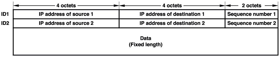
Data message format of IFNCPA.
The first field ID1 of the encoded data message holds the ID of the native data previously received and kept in the encoder buffer to hold received data, and the second field ID2 holds the ID of the native data received subsequently and appropriate for the relay. For example, in Figure 1, ID1 and ID2 of the encoded message
For simplicity, we assumed that the message size is a fixed length. In fact, however, the XOR operation is applicable for variable message length if a message length field is introduced in ID format. Suppose that data chunk
Transmission on MAC/PHY layer
Recall that a data message is a PDU on the application layer. When a message which includes encoded data chunk is transmitted, its destination IP address is set to the broadcast IP address. Thus, the destination MAC address also becomes the broadcast MAC address, and broadcast transmissions are executed on the MAC layer. The IP address of the destination node for the data chunk is stored in the ID field, so this information is never lost. As a result of this broadcast transmission, the message reaches an IFNCPA-type entity of the application layer of the neighboring node.
As shown in Figure 3, when the receiving node is a (final) destination, the IFNCPA-type entity replies an explicit ACK message, which is also a PDU on the application layer like a data message. An explicit ACK message includes only the ID of the data chunk to be acknowledged and it is sent in a unicast transmission to the neighboring node to be acknowledged.
In this study, the data rate of MAC is assumed to be the same among all nodes.
Communication model
In Figure 1(b), the relay node
Let us generalize this to a communication model as shown in Figure 7. Here, we focus on node

Communication model.
A native data chunk of
Basic idea to avoid passive ACK collisions
Let us explain a mechanism to avoid passive ACK collisions as much as possible, the necessity of which was mentioned in section “Issue 2: Avoiding collisions of passive ACK packets,” referring again to Figures 4 and 5. This mechanism attempts to avoid collisions between messages for passive and/or explicit ACK by delaying the transmission of one message by the offset time as shown in Figures 8 and 9.

Effect of offset to avoid passive ACK collision case 1.

Effect of offset to avoid passive ACK collision case 2.
In this study, we assume that the length of data chunk and the data rate are both constant. Let
As shown in Figure 9, the timing of transmissions
Transmission procedure
Regardless of an encoded message or a non-encoded message, the IFNCPA entity temporally stores the transmitted data chunk and the associated ID in its decoder buffer until it receives the corresponding ACK. Note that the data chunk and its ID stored in the decoder buffer are also used when the IFNCPA entity extracts native data chunk from a directed encoded data message.
In the case of the encoded data message, such as message
In the case of the non-encoded data message, such as message
Reception and relay procedure
When receiving an encoded data message, the IFNCPA entity determines whether it is “directed” to itself or not. If the encoded data message includes the native data chunk that the entity has transmitted and holds in the decoder buffer, the message is “directed” as explained in section “Communication model.” Then the entity extracts the native data chunk to be received or relayed by decoding from the message and the other native data chunk stored in the decoder buffer. Otherwise, the message is discarded since it is not directed. When receiving a non-encoded data message, the entity simply receives the native data chunk of the message since it is unicast.
The received native data chunk is concluded to arrive at the (ultimate) destination if the current node’s IP address matches the destination node’s IP address included in the ID associated with the native data chunk. Otherwise, the received native data chunk should be relayed, so that the next-hop node is determined according to the destination IP address based on the routing policy.
If the native data chunk is conveyed at the ultimate destination by the encoded data message, say
Immediate transmission is performed if either of two conditions holds:
If the native data chunk to be relayed cannot find other native data encodable with itself in the encoder buffer, it is stored in the encoder buffer along with the associated ID and IP address which were sent with it from the neighboring node. At the same time, the encoding latency timer is started for the native data chunk, as described in section “Determining the appropriate encoding latency and time-outs.” When the encoding latency for the native data chunk times out, it is unicast to the next-hop node immediately or after waiting for the offset time
Determining the appropriate encoding latency and time-outs
This section explains how to determine the encoding latency. As described in section “Issue 1: determining the appropriate encoding latency,” the best policy is to wait for the usual interval between packet arrivals from counterflow. However, a maximum value is set for the encoding latency to suppress the end-to-end delay to some extent.
Let us return to the communication model shown in Figure 7. Here, without any loss of generality, we focus on the


where

where
When passive ACK is employed, how long retransmission should be refrained from is an important issue. For example, the longer is the encoding latency of the neighbor nodes, the longer is the time to receive the passive ACK. The variables


Parameter tuning and basic evaluation
This section describes the process of tuning the control parameters of the IFNCPA scheme: the encoding latency coefficient
Encoding latency coefficient
As stated in section “Determining the appropriate encoding latency and time-outs,” the encoding latency must be set as appropriate to the load. Let us examine the encoding latency coefficient

When

Using the probability density function
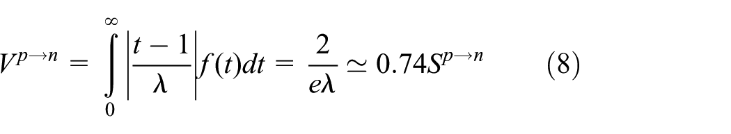
From equations (7) and (8),
Maximum encoding latency
As described in section “Determining the appropriate encoding latency and time-outs,” it is essential to suppress the transmission delays because the encoding latency lengthens especially when the traffic load is low. The parameter established for this, maximum allowed value
In ITU-T G.114, 21 it is recommended that a one-way delay of 400 ms should not be exceeded for general network planning. According to ITU-T G.1010, 22 the delays of less than 150 ms are preferred and those of 400 ms are a limit for audio or video applications. Therefore, the end-to-end delay (allowed delay) was set at 150 ms hereafter.
Next, the application was considered in an interior environment. The width of the building was varied from several tens to several hundreds of meters, the transmission distance was varied from several tens to 100 m, and the maximum hop number end to end was set at 10. Accordingly, dividing the allowed delay by the maximum hop number, 15 ms was set to the maximum
Offset
As described in section “Basic idea to avoid passive ACK collisions,” the offset
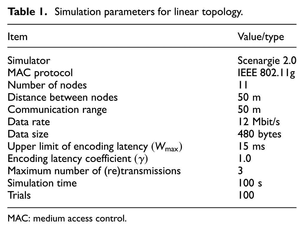
A total of 11 nodes were created in this simulation, spaced at equal intervals, to obtain
Simulation parameters for linear topology.
MAC: medium access control.
The mean encoding ratio,
Figure 10 shows how the mean encoding ratio varied with the load. There was almost no difference between

Mean encoding ratio when the encoding latency was varied.

Collection ratio when the encoding latency was varied.
Figure 12 presents the end-to-end delay as it varied with the load. The delay was greater at

Delay when the encoding latency was varied.
From the results in Figures 10–12, the offset was set to
Basic evaluation of the bidirectional communication environment under symmetric loads
A basic evaluation of the bidirectional communication environment was carried out while the model was under symmetric loads. Table 1 presents the parameters for this simulation; also,
Figure 13 shows how the mean encoding ratio varied with load under both the IFNCPA scheme and the IFNC scheme. IFNC resulted in lower ratios than for IFNCPA; the reason for this was probably that there were no retransmissions of encoded packets due to passive ACK, whereas a greater number of encoded packets gave a greater likelihood of “losing” one due to collision. In addition, during low loads, the encoding latency under the IFNCPA scheme was reduced to less than the mean packet arrival interval using

Mean encoding ratio under symmetric loads.
Figure 14 depicts how the collection ratio changed with load. Since the IFNC scheme does not equip with retransmissions, it has lower collection ratios than the IFNCPA or unicast scheme. Comparing the IFNCPA and unicast schemes, it is clear that the former has a higher collection ratio even under high loads and thus is a superior scheme to unicast. This is because the IFNCPA can lessen the number of transmitted packets, thanks to NC, while realizing reliable transmission, thanks to the passive ACKs.
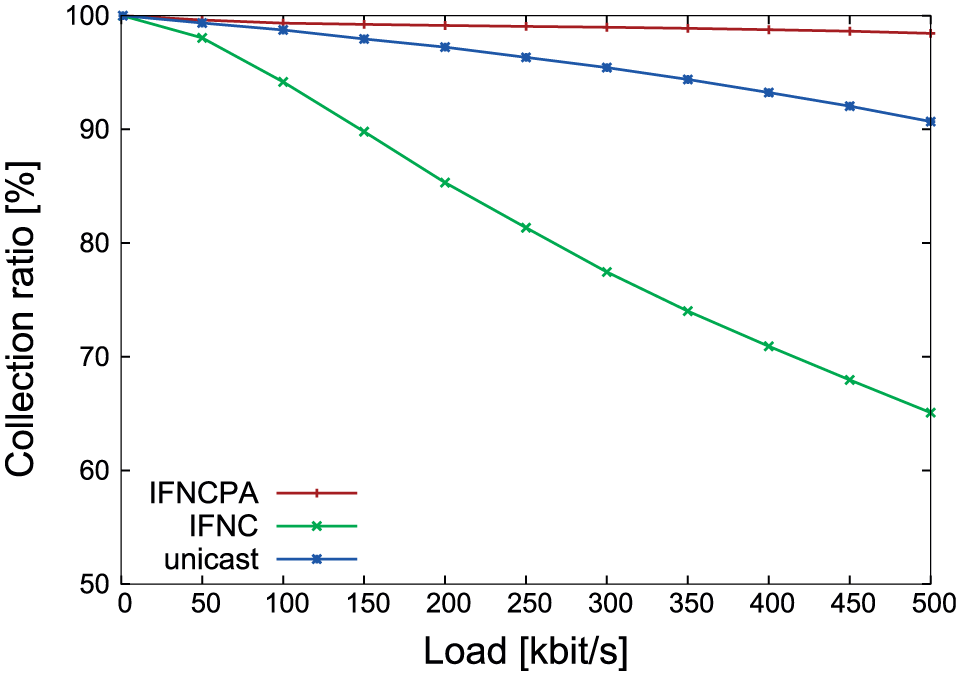
Collection ratio under symmetric loads.
Figure 15 provides the results for delay versus load. The reason for the lower delays under the IFNC scheme than under IFNCPA is that the retransmissions due to the passive ACK feature in IFNCPA increase the delays. Comparing IFNCPA to unicast, IFNCPA again shows longer delays because of the encoding latency; these delays all remained under the allowed delay of 150 ms at all loads.

Delay under symmetric loads.
These simulation results indicate that IFNCPA provides higher collection ratios than does IFNC or unicast, and its delays remain within the allowed delay; therefore, it is a more effective scheme in a bidirectional communication environment under symmetric loads.
Basic evaluation of a bidirectional communication environment under asymmetric loads
The previous section presented a simulation of operation under the IFNCPA scheme in a bidirectional communication environment under symmetric loads, which is an ideal environment for IFNCPA. However, it is also essential to examine whether this scheme remains effective in an environment under asymmetric loads. In this section, therefore, a basic evaluation of a bidirectional communication environment under asymmetric loads is performed. The ratio
Figure 16 is a graph of the mean encoding ratio with respect to load asymmetry under the IFNCPA scheme. These results show that a greater degree of asymmetry is associated with a greater mismatch in directions of traffic and lower mean encoding ratio.

Mean encoding ratio under asymmetric loads.
Figure 17 shows how the collection ratio varied with load asymmetry. From these results, the high collection ratio under the unicast scheme is explained as follows: the greater the degree of asymmetry, the greater the mismatch in directions of traffic, and the lower the probability of collisions between packets flowing in opposite directions. Under the IFNCPA scheme, packet collisions were reduced by the diminished traffic thanks to IFNC, so those schemes always showed higher collection ratios than the unicast scheme.
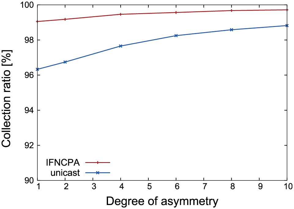
Collection ratio under asymmetric loads.
Figure 18 presents the variation in delay with load asymmetry. Under the IFNCPA scheme, the delay increased with degree of asymmetry. The maximum delay was over the allowed delay of 150 ms when the degree of asymmetry is over about 3.5. This was caused by resulting increased RTO, which was calculated according to equations (4) and (5), because the disproportionate amount of traffic leads to the larger RTO in the traffic flow of one direction. If the RTO is limited to reduce the end-to-end delay, there is a possibility that the encoding efficiency is lowered. Investigation on this will be left as a future study.

Delay under asymmetric loads.
These simulation results demonstrated that IFNCPA provides a higher collection ratio than unicast at the cost of end-to-end delay. Therefore, IFNCPA is an effective scheme in a bidirectional communication environment under the condition that the degree of asymmetry is less than 3.5.
Evaluation of practical applications by simulation
As described in section “Introduction,” the proposed scheme was employed in a model of the disaster response system using a wireless sensor network as an example of a practical application. The role of a sensor in a system such as this is to become disconnected from the network due to fire; therefore, the system cannot be a single-sink wireless network but rather a multiple-sink wireless network 24 in order to be sufficiently robust.
In support of evacuation and rescue, it is essential to obtain information not only about the event itself but also about potential victims of disaster who have deliberately stayed in vulnerable locations or waited too long to flee.25,26 Wireless sensor network–based evacuation and rescue systems must employ packet transmission protocols that ensure high efficiency and reliability of transmission between nodes and sink nodes of any information gathered and delivered. Therefore, as described in this section, a multi-sink wireless sensor network–based evacuation and rescue system for disaster warning in a building was designed, and simulations were carried out for scenarios modeling bidirectional communication in such a system.
Simulation settings
This simulation evaluated a scenario employing a total of 28 nodes, comprising 26 sensor nodes and 2 sink nodes, on a single floor of a building (see Figure 19). As a result, the topology was nonlinear in this section, unlike the previous section. The model was based on a large (100 m × 450 m) shopping center, Aeon Lake Town, in Saitama Prefecture, Japan. It was assumed that the exterior and interior walls were of identical materials and thicknesses. Two types of traffic were generated to realize multiple bidirectional communications. In the first, sink nodes at each end of the model generated data packets at intervals according to identical exponential distributions (Traffic 1). In the second, the sensor nodes indicated in the figure by black circles were employed as source nodes, transmitting data packets with the identical exponential distribution to the sink nodes at each end of the model (Traffic 2). The sensor nodes without black circles act as relay nodes. The IFNCPA and unicast schemes were evaluated.

Floor structure and node placement.
A commercial simulator Scenargie 2.0 was also used for performing this simulation. The parameters for this simulation are as shown in Table 2. Optimized Link State Routing (OLSR)
27
was the routing protocol and indoor radio propagation model was COST231 Indoor. The equations below use

Simulation parameters for use-case.

MAC: medium access control.
The path losses


where
Results and observations
Figure 20 presents the mean encoding ratio as it varied with the load under the IFNCPA scheme. The IFNCPA (Sink, Sensor → Sink) results indicate the combination of Traffic 1 and Traffic 2 findings, and the IFNCPA (Sink → Sink) results indicate the Traffic 1 findings. The mean encoding ratio increases to only around 25%, even at high loads, in the IFNCPA (Sink, Sensor → Sink) results. This was probably due to the occurrence of single-hop transmissions in which the messages traveled directly from their source nodes to their destination nodes, never passing through relay nodes, and thus, never being encoded at all. The IFNCPA (Sink → Sink) results, in which transmission was only between sink nodes, show an increase in mean encoding ratio with an increase in loading, to about 64%.

Mean encoding ratio: use-case.
Figure 21 shows the collection ratio versus load. The unicast (Sink, Sensor → Sink) results indicate combined Traffic 1 and Traffic 2 findings, and the unicast (Sink → Sink) results indicate just Traffic 1 findings. Comparing the IFNCPA and unicast findings, the IFNCPA scheme provided higher collection ratios, including at high loads. Under the unicast scheme, Traffic 1 showed lower collection ratios than the combination of Traffic 1 and Traffic 2. This was probably due to a higher mean number of hops during Traffic 1, resulting in a greater number of message collisions.

Collection ratio: use-case.
The variations in delay with respect to load are provided in Figure 22. The delay increases slightly with the load. This was attributed to increases in the number of collisions of passive ACK packets when the load became too high, necessitating many retransmissions. Comparing the IFNCPA and unicast schemes, there are delays due to the encoding latency under IFNCPA, so it showed longer delays than did the unicast scheme, but both the schemes had delays remaining within the allowed delay of 150 ms except the IFNCPA (Sink → Sink). In the IFNCPA (Sink → Sink) results, the end-to-end delay is below the allowed delay of 150 ms with load up to 0.9 Mbit/s, but at and above a load of 0.9 Mbit/s, it is over 150 ms but still below 200 ms. Finally, comparing the combination of Traffic 1 and Traffic 2 with Traffic 1 alone, the latter had higher delays. This was probably due to the higher mean number of hops in Traffic 1 condition.

Delay: use-case.
These simulation results indicated higher collection ratios under the IFNCPA scheme than under the unicast scheme, that is, IFNCPA scheme is more reliable than the unicast scheme. The IFNCPA scheme has delays within the allowed value under a certain traffic load about 0.9 Mbit/s even for Traffic 1. These results suggest that the IFNCPA scheme is effective in an environment where the load is not extremely high.
Conclusion and remarks
In this study, the message transfer protocol of a scheme referred to as IFNC with passive ACK (IFNCPA) was proposed for the objective of highly efficient and reliable message transmission in a bidirectional communication environment. A system was investigated that would determine the encoding latency, a control parameter in IFNCPA, in a dynamic fashion with reference to the message arrival interval while addressing the issue of passive ACK collision. Parameter tuning was carried out and the effectiveness of the IFNCPA scheme was confirmed in a basic evaluation using a simulation assuming a linear network topology. A more realistic model of a wireless sensor network for evacuation and rescue systems accommodating bidirectional communication was simulated as an example of a practical application, and the IFNCPA scheme was shown to be effective and to have delays within the allowed value under a certain traffic load.
Since NC generates encoded data message from a plurality of data messages, an encoding waiting time is required. Therefore, there is essentially a trade-off between the encoding ratio and the end-to-end delay. In fact, only throughput performance was investigated in the past studies on IFNC12–17 mentioned in section “Introduction.”
18
From our simulation results, IFNCPA is considered to be useful for applications that can tolerate about a few hundred milliseconds for the end-to-end delay. Note that although the end-to-end delay is still below the limit of 400 ms for audio or video applications,
22
it exceeds the allowed value of 150 ms in the environment under asymmetric and high traffic load. This is because
Future research should feature experiments with actual equipment for evaluation of this approach and address routing protocols for effectively incorporating the IFNCPA scheme in equipment.
Footnotes
Handling Editor: Stefano Avallone
Declaration of conflicting interests
The author(s) declared no potential conflicts of interest with respect to the research, authorship, and/or publication of this article.
Funding
The author(s) disclosed receipt of the following financial support for the research, authorship, and/or publication of this article: This work was supported by JSPS KAKENHI grant nos 24500080, 15K00124, and 15K00125.