
Abstract
In many logistics applications, densely placed objects on high-speed conveyor belts are attached with passive tags for automatic identification and sorting to work more efficiently. Traditional localization or sorting methods cannot effectively work in such scenarios due to complex environments. In this article, we propose a new passive radio frequency identification sorting system for dense mobile tags on high-speed conveyor belts by utilizing the output phase. At first, a relative motion model is utilized to get the zero point time when the object passes the radio frequency identification portal. Then, the coarse-grained time and the corresponding speed of the conveyor belt are obtained by the phase curve fitting. Finally, the inverse synthetic aperture radio frequency identification is used to get the fine-grained zero point time, which is realized based on the holographic image reconstruction. And the particle filter is utilized to get a significant reduction of computational burden. The proposed method is implemented with commercial-off-the-shelf devices, and the evaluation results in various scenarios show our system can achieve an average accuracy of 97% with the tag density of 10/m and at a speed of 4 m/s.
Keywords
Introduction
The Internet of Things (IoT) is the key to industrial upgrading, which has been attracting increasing attention in both academia and industry recently. At the same time, as an important component of industrial automation, radio frequency identification (RFID)-based conveyor belts are widely deployed in many applications to identify objects quickly and improve work efficiency, such as postal sorting offices and airport baggage handling systems.
Moreover, sorting of the objects in conveyor belt systems is an important problem. Item-level processes can only be done correctly after knowing the order or the location of each object. The operation that the RFID-based conveyor belt systems distinguish objects and then deliver them to the proper destinations is usually called sorting. In these systems, the RFID reader antennas are fixed on a gate above the conveyor belt, which is called the RFID portal. Furthermore, in order to work more efficiently, objects are usually densely placed on high-speed conveyor belts which makes sorting more difficult. Both the increasing number of tags in the RFID interrogation zone and the reduction of the dwell time that a tag stays in the interrogation zone make sorting challenging.
For example, in some high-speed conveyor belts of liquor factories, RFID sorting system is used to check whether the RFID tag attached on each bottle of liquor is initialized successfully. Due to the dense and high-speed bottles on conveyor belts, special devices like near-field antennas or shielding devices are used. In these practical industrial fields, the core idea of accurately sorting objects on RFID-based conveyor belts is to limit the RFID interrogation zone to ensure that there is only one tag at a time. There are still some incorrect operations and it works better for sparse object placement. Researchers1,2 utilize the time when the tag enters the interrogation zone or received signal strength indication (RSSI) to estimate the order of the objects. However, these techniques cannot work for dense objects. The RFID interrogation is based on a probabilistic algorithm, 3 which means tags’ replies are random. And RSSI is seriously affected by noise and multi-path effect in industrial environment.
In recent years, other low-level data like phase provided by commercial-off-the-shelf (COTS) RFID readers have been exploited by the state-of-the-art systems to serve the needs of sorting on conveyor belts. Tagoram 4 and Buffi et al. 5 leverage synthetic aperture radar (SAR) concept to locate RFID tags on a conveyor belt with a centimeter-level accuracy. However, they require the prior knowledge about the speed of the conveyor belt, which may not be measured accurately. Besides, they do not consider the angle-dependent phase response of the antenna and have a heavy computational burden. STPP 6 analyzes the spatial–temporal dynamics of phase for sorting, but it requires a strong consistency among RFID tags and suffers from low read rate on account of high-speed conveyor belt.
As dense tags move fast on conveyor belts, the measurements may be sparse and thus require intelligent processing of the tag measurement results, while previous methods cannot provide sufficient accuracy to differentiate and track each tag. Therefore, we present a lightweight passive RFID sorting system (PRSS) for dense objects on high-speed conveyor belts based on COTS RFID devices. The contributions of this article are as follows.
First, a relative motion model and a phase curve fitting method are proposed to get the coarse-grained time when the object passes the RFID portal and the corresponding speed of the conveyor belt. In this step, PRSS filters out those objects which are not on the conveyor belt.
Second, inspired by other synthetic aperture RFID localization systems, we utilize the obtained coarse-grained time and matched filter for holographic image reconstruction to get the fine-grained time and the location of each tag with a light computational burden, which is further reduced by particle filter. We also analyze the theoretical −3 dB width of ambiguity for the hologram.
Finally, a prototype system is built and extensive experiment results show that it achieves up to 97% sorting accuracy on average. It has a high tolerance for the interference, multi-path, and other noise.
The rest of the article is organized as follows: the related works are presented in section “Related works.” In section “Background,” the background is introduced. The research methodology and algorithm design are illustrated in section “Research methodology and system design.” In section “Evaluation,” the performance evaluation of the system is analyzed. And finally, this article is concluded in section “Conclusion.”
Related works
The sorting problem is also a localization problem, and a great number of systems utilize RFID to identify and track objects. Our work is standing on the shoulders of previous works.
In theory, the RSSI value is inversely proportional to distance between the RFID reader antenna and the tag. 7 Early indoor localization systems like SpotON 8 and Landmarc 9 usually utilize RSSI with the radio propagation model or fingerprint map for location estimation. Some device-free systems10–12 monitor the activities of target objects by the changes of the signals from the reference tag array, but the reference tag array is almost impossible to be deployed on the conveyor belt.
RSSI is also regarded as a basis of RFID sorting system. Combined with hidden Markov model1,13 or response reception ratio, 2 RFID tags are sorted with a 0.5 m luggage distance. However, RSSI is sensitive to the environment noise, so it is still hard to get a satisfying precision of dense tags in a high-speed scenario.
Phase-based RFID localization is proposed by many research communities based on its proportional relationship to the propagation distance. 14 Some special devices are applied for phase or phase difference measurement, such as the special two-antenna array, 15 the rotating antenna, 16 software defined radio, 17 near-field cascaded shelf antennas, 18 and multiple receivers with one transmitter. 19 A joint iterative phase reconstruction with weighted localization algorithm 20 or hyperbolic localization algorithm 21 is also utilized for the localization of static tags. Tadar 22 tracks one mobile object by extracting reflections off the moving object with a learning phase. RF-scanner 23 uses the super V-zone of the phase profile to pinpoint the tag position. These systems are hardly used for the dense objects sorting on the high-speed conveyor belt.
Then, RFID-based localization is incorporating with SAR 24 in recent years to accurately locate stationary tag with a known trajectory of a reader antenna. 25 This method is called synthetic aperture RFID localization, and the known trajectory is the synthetic aperture. In contrast, a mobile RFID tag with a known trajectory is located based on the inverse synthetic aperture RFID in one dimension, 26 two dimensions, 27 and three dimensions. 28 MobiTagbot 29 excludes sample points where multi-path is likely prevalent to improve the accuracy. And it also can be utilized to capture multi-path profiles 30 for localization. The coherent reconstruction in synthetic aperture RFID localization leads to an effective multi-path distortion suppression. However, it is a pity that they all have a high computational complexity.
The output phase values are also utilized for sorting systems. STPP 6 utilizes the change of RFID phase and the change sequence to calculate the order of tags. But it suffers from the consistency among RFID tags and low read rate in dense tags with a high-speed scenario. Similar to other synthetic aperture RFID localization systems, normal coherent reconstruction 5 or differential augmented coherent reconstruction in Tagoram 4 is utilized to locate RFID tags on a conveyor belt with a centimeter-level accuracy. But they demand accurate prior knowledge about the speed of the conveyor belt, and do not consider the angle-dependent phase response of the antenna. These existing sorting systems can hardly sort the dense objects with a high speed due to the heavy computational burden and the interference from those tags not on conveyor belt in the industrial scenario.
Background
In this section, the sorting problem of dense tags on high-speed conveyor belts is described. And the output phase of RFID reader is introduced.
Problem specification
As shown in Figure 1, a sequence of objects attached with RFID tags moves along the conveyor belt at a velocity of
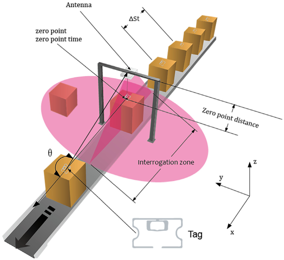
Dense tags on a high-speed conveyor belt.
For each tag, the trajectory from its first interrogation to the last interrogation is its aperture. Meanwhile, each point where the antenna interrogates the tag is known as aperture point. For convenience, the point where the tag is directly under the RFID portal is defined as zero point (the line connecting the tag and the reader is perpendicular to the x-axis). The time when the tag is at the zero point is defined as zero point time, and the distance between the antenna and the tag at the zero point is called zero point distance.
Suppose that the conveyor belt speed is
Output phase
Modern COTS RFID readers like Impinj 420 in PRSS can report the phase value


Research methodology and system design
In this section, major methodology and the system design are introduced. The system contains three stages: first, radial velocity is calculated to get the initial zero point time and filter out those tags which are not on the conveyor belt. Second, the curve fitting is used to obtain the coarse-grained zero point time and the corresponding speed of the conveyor belt. Finally, the more accurate zero point time is estimated by advanced holography-based sorting. The detailed relationship of three stages is shown next.
Radial velocity-based sorting
When a tag crosses the RFID portal, the change of phase value is regular: two consecutive phase values are decreasing before the zero point while increasing after the zero point. To find the zero point time, the radial velocity
Along the conveyor belt,

The effectiveness of radial velocity estimation: (a) the output phase values and the radial velocity (v = 4 m/s, the zero point time is 252 ms), (b) the CDF of the time needed to identify one tag twice, and (c) the maximum interval along the conveyor belt (v = 4 m/s and h = 0.5 m).
It is noticed that the phase values are discontinuous and the phase points are sparse. That is because the reader takes a modulo
Then, we explore the time needed to identify one tag twice. Different numbers of static tags are placed in the interrogation zone of the reader and each experiment lasts 5 min. As illustrated in Figure 2(b), when the number of tags is 15, in over 80% cases, the time needed to identify one tag twice is less than 40 ms. And the maximum time needed to identify one tag twice is about 70 ms when the number of tags is 20. Is this interval long enough for the radial velocity estimation?
If a tag moves
As mentioned before, it is hard to recognize whether the phase is increasing or decreasing because of the modulo operation. Fortunately, the conveyor belt is a special situation: the phase monotonically decreases before zero point and then monotonically increases. The time that a tag needs to move
For the consecutive points which satisfy
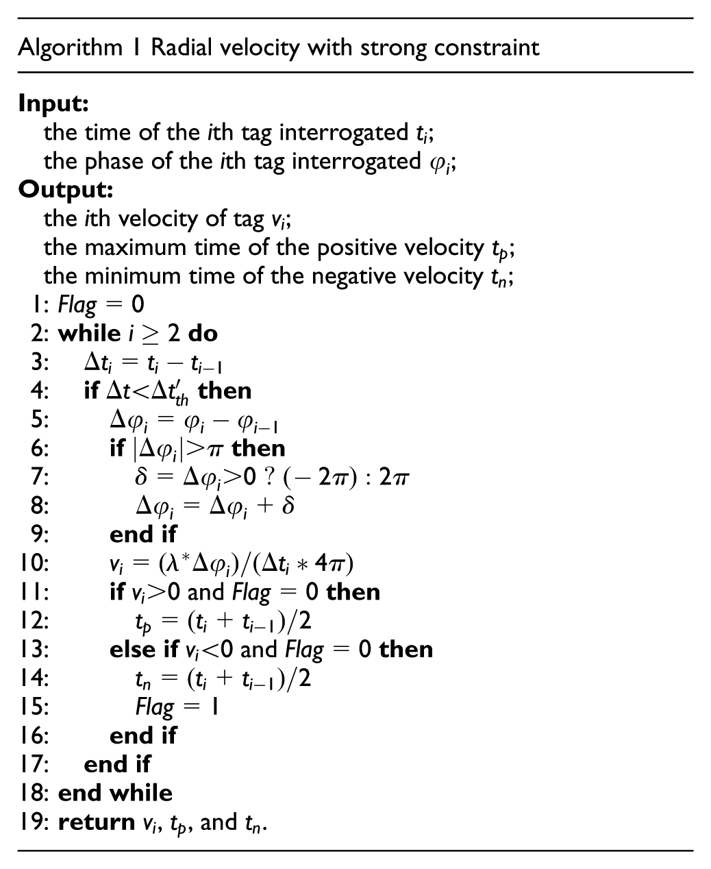
As discussed above, the radial velocity can be estimated effectively with small interval between two consecutive aperture points. As illustrated in Figure 2(b), over 60% of time differences between two consecutive interrogations are less than 40 ms, making velocity estimation practical. So, the radial velocity can be effectively estimated by Algorithm 1. After getting the maximum time of the positive velocity
In one experiment, 10 tags with a 10 cm spacing move along a conveyor belt at a speed of 4 m/s, and most of them are interrogated about 20 times in the interrogation zone. Then their radial velocity in one experiment is shown in Figure 3. The changes of radial velocity of every tag can be conveniently taken and the zero point of each tag can also be easily recognized. Only the order of tag 5 and tag 6 is nearly incorrect. The calculated velocity fluctuates wildly especially away from the zero point because the tag in the edge of the interrogation zone cannot be interrogated stably. But near the zero point, radial velocity is accurate. The values that do not satisfy the threshold criteria are ignored. Although the velocity values may be inaccurate, the change trend of velocity values is correct and really matters, which can be used to estimate the zero point time correctly. Furthermore, some more accurate methods are employed next.

Velocity-based tag sorting (
The curves in Figure 3 also show a uniform linear motion with the conveyor belt speed, which can be utilized to detect whether the tags are on conveyor belt or not. If the interrogated tag is not on the conveyor belt, its radial velocity will be different. Due to the noise, the radial velocity of static tags fluctuates around zero. The mobile tags with different directions can also be easily filtered out due to monotonically increasing. For the mobile tags with same direction, the slope of the velocity curve around the zero point may be different from that of normal tags. In addition, according to OTrack, 2 the read rate of the tag on the conveyor belt stabilizes at a certain high value around the zero point. After getting the zero point time, the read rate within 200 ms range of the zero point time is also calculated for detecting tags not on conveyor belt. From Figure 4 (an experiment with 10 interference tags), we can easily search for a threshold to filter out these tags. The threshold depends on the conveyor belt speed and the tag spacing, and it can be learned by simple classification method like logistic regression.

Detect those tags not on conveyor belt (red circles represent tags on conveyor belt, while blue crosses denote those tags not on conveyor belt).
Phase curve fitting-based sorting
The radial velocity-based tag sorting method treats the average velocity in short time as an instantaneous velocity. When the density of tags increases, the sampling interval will increase due to the reduction in read rate. This will result in an offset of the zero point estimation.
For a linear conveyor belt, if the conveyor belt speed is

The curve fitting technique can be used to estimate the zero point time

Phase curve fitting-based sorting (
As shown in Figure 2(a), there is a “V-zone” from 160 to 350 ms, where the tag moves through the zero point in this cycle. In PRSS, only the points near the zero point are selected for integration to avoid the phase difference over
So, PRSS only integrates (unwraps) the phase data around the zero point for curve fitting. If the interrogation point closest to the zero point is
The integrated phase values are substituted into equation (3). Then, the problem can be easily converted to find

where
Then, Levenberg–Marquardt algorithm is used.

where
Obviously,
Normal holography-based sorting
The noise will weaken the performance of previous method. As aforementioned, synthetic aperture RFID localization can get accurate results. For simplicity, it is assumed that there is only one antenna at first.
PRSS focuses on the zero point time and the zero point distance, which also simplifies the three-dimensional (3D) space location. Suppose the zero point time is
From equation (1), if an assumed pair
The phase difference

where
At a point near the assumption, the value of
This vector sum is also called the coherent reconstruction of a holographic image, and the output of the matched filter can be regarded as the amplitude of a holographic image, which is shown in Figure 6 with the same data used in Figures 2(a) and 5. This method can get an accurate zero point time.
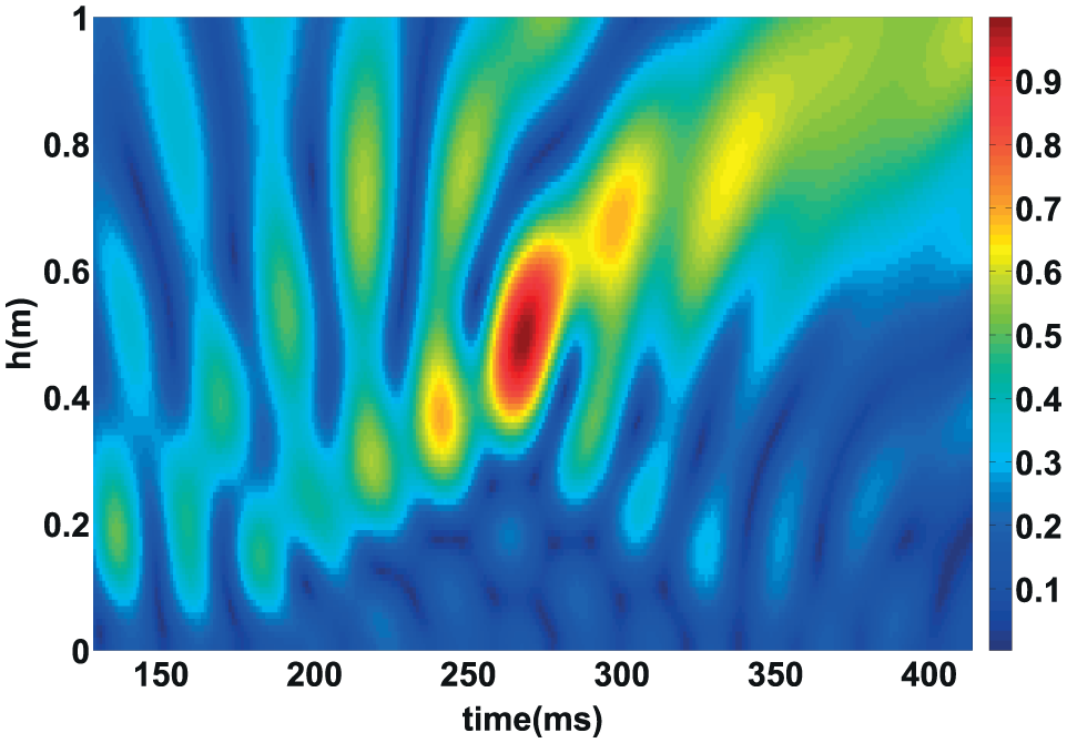
Holographic image calculated with test data
The likelihood function


where the distance between the aperture and the reader antenna
To get the lateral resolution,

Similarly, the 20% loss in intensity width in radial direction can be calculated based on the Fresnel integral

It is obvious that
Equation (6) can be simplified if the trajectories of all tags are in the same line because the zero point distance

where
Phase value calibration
The error of the measured phase, especially the regular error, would result in the performance degradation of PRSS. In the coherent reconstruction, the antenna is abstracted as a point. However, the actual antenna cannot be abstracted as a static point simply. Its phase center moves on the evolute of the equiphase wave front and can only be seen as a constant for small changes of the angle of arrival. 25 The phase response of the antenna is angle-dependent.
If the antenna at

The phase response changes along with the angle-of-arrival (the blue point is the measured data while the red curve is the fitting curve
In most scenarios, if there is a long aperture, the main localization error stems from the phase center drift, rather than the multi-path or noise which is suppressed during the reconstruction. With phase calibration, a better accuracy can be achieved.
Advanced holography-based sorting
The computational burden of the normal holography-based sorting is heavy. Even for a 2D holographic image with NM pixels and
In fact, most of the assumed points have a low likelihood value, so a simplified version of particle filter can be used. If a set of weighted particles is utilized to represent the pixels, the computational burden can be effectively reduced. Enough particles can get the accurate zero point time. And the particle number is subsequently reduced with a resample algorithm after iterations.
The zero point
At first, all pixels in the holographic image are set as particles

The positions of these son particles are the same as their fathers’. After
Moreover, not all phase values from aperture points are used for sorting in this stage. The aperture points far away from the zero point are more likely to have bigger measured error. And when the tag is far away from the antenna, it can be interrogated usually due to complex multi-path. With the help of the first two stages, aperture points are selected around the zero point at the range of 1 s.
PRSS design
Radial velocity-based sorting uses the average velocity during a short time to approximate the instantaneous velocity. This approximation will result in inaccuracy due to the long interval between two consecutive aperture points, especially when the tag is around the zero point, caused by dense tags and high speed. But it has the minimum computational burden. Phase curve fitting-based sorting needs to unwrap the phase values. This unwrapping seriously suffers from the sparse aperture points, especially when there are no interrogation points in some cycle. These two methods need enough aperture points to ensure the accuracy. Holography-based sorting achieves the highest accuracy with the maximum computational burden.
Putting things together, we get PRSS, the quick and correct passive RFID sorting method for dense objects on high-speed conveyor belt, which is illustrated in Figure 8.

The PRSS architecture.
First, PRSS utilizes radial velocity-based method implemented with minimum computational burden to get the zero point time
Second, according to
Finally, the advanced holography-based method is used. The search scope of the assumption zero point time and zero point distance is determined by the coarse-grained results from previous methods. Then, the fine-grained results are estimated in real time and the sequence is updated according to the fine-grained zero point time.
As noted above, the exact speed of the conveyor belt is significant. Due to the stability and the consistency of the conveyor belt’s speed with RFID tags, the Levenberg–Marquardt algorithm and the speed search in holography-based method are used to get the speed of the conveyor belt for the first 20 tags. And the average value is utilized for the holography-based method next.
In addition, RFID portal is usually equipped with more than one antenna. It will take extra time for antenna switching, which means a lower read rate. On the other hand, the advanced holography-based method achieves higher accuracy than other two methods. As shown in equations (9) and (10), its lateral accuracy (x-direction in Figure 1) is much better than others (perpendicular to x-direction). More importantly, the sorting system mainly focuses on the lateral positions of the dense objects on conveyor belts, especially for the linear conveyor belt, which is the most common. So, PRSS employs one antenna for sorting, while it is convenient to extend to multi antennas.
Evaluation
In this section, we present the implementation of PRSS and conduct its performance evaluation.
Implementation
We adopt a COTS RFID reader Impinj 420 with a Larid S9028PCR antenna and UPM tags without any modification for PRSS. The RFID reader operates at about 920 MHz, whose wavelength is about 0.32 m. The reader mode is set as “Dense Mode (M=4)” for the practical industrial settings and the transmit power is 20 dBm. The experiment environment is depicted in Figure 9. The maximum speed of the conveyor belt is 240 m/min, which can meet the demand of most applications. And we place the antenna on a RFID portal at a height of 1.5 m over the conveyor belt. Some tags are regularly or irregularly attached to the boxes. Low-level reader protocol (LLRP) 31 extended by Impinj is regarded as a communication approach between the computer and the reader. We implement PRSS using C# on a computer equipped with an Intel Core i7-4790 CPU 3.6 GHz and a 16 GByte memory.
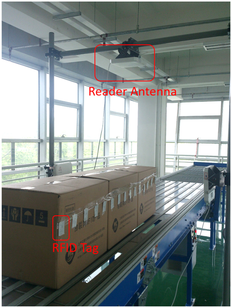
Dense tags on conveyor belt across the RFID portal.
There are two parameters that dramatically affect the system performance.
The speed of the conveyor belt determines the dwell time of a tag in the interrogation zone. A longer time length means more interrogation times and smaller phase difference between two consecutive interrogations.
The tag spacing affects the number of tags in the interrogation zone and the interrogation times of a tag. Due to the RFID air interface protocols C1G2, 3 a shorter spacing brings more collisions, which means less effective data. Densely placed tags also cause the threshold of effective velocity to be small.
The performance of PRSS
We compare PRSS with other three sorting systems, Tagoram, 4 STPP, 6 and OTrack. 2 For evaluation, the accuracy ratio is calculated by dividing the length of the longest subsequence with the correct order by the total number of tags on the conveyor belt.
At first, the tag spacing is fixed at 10 cm and the speed of the conveyor belt changes from 0.5 to 4 m/s. The interrogation zone is about 0.5 m long. Only one antenna is used, while there are 15 tags across the RFID portal in one experiment. As shown in Figure 10(a), OTrack and STPP suffer a lot from the high-speed conveyor belt, high density of tags, and short dwell time in the interrogation zone for each tag. Tagoram is also a synthetic aperture RFID localization system, which has similar performance to PRSS (both over 95% and even the speed is 4 m/s).

Performance comparisons of different sorting systems: (a) different speeds of conveyor belt, (b) different tag spacings, and (c) with unknown conveyor belt speed.
Then, we fix the speed of the conveyor belt at 4 m/s and change the tag spacing from 7 to 20 cm. As illustrated in Figure 10(b), STPP and OTrack have some improvement with the increasing spacing. But due to less samples, they are unsuitable for sorting objects on high-speed conveyor belts. PRSS and Tagoram have similar performance. On account of the phase calibration and the aperture points screening, PRSS is a little better.
The performance of holography-based sorting (PRSS and Tagoram) also depends on the accuracy of the aperture position, which is determined by the conveyor belt speed. The aperture length is about 0.5 m and the tag spacing is 10 cm. If the speed (3.9 m/s) of the conveyor belt is unknown or known incorrectly (known as 4 m/s), the sorting accuracy is depicted in Figure 10(c). Without the exact speed of the conveyor belt, the performance of Tagoram decreases a lot. If the speed is wrong, the longer the aperture is, the lower sorting accuracy ratio is achieved. So, the speed search is necessary, which can be obtained by equation (11). At the same time, although STPP and OTrack are insensitive to the prior speed knowledge, they are unsuitable for sorting dense objects on high-speed conveyor belts.
The number of aperture points
So, PRSS is adaptive for the unknown high speed of the conveyor belt and the dense objects with a small delay. And the tags sorting with 97% accuracy on average is achieved, when there are 10 tags/m and the speed is 4 m/s. PRSS achieves high accuracy with good robustness. Its first two methods can narrow down the search scope and reduce the computation burden, while the holography-based method improves the accuracy.
Detection of tags not on conveyor belt
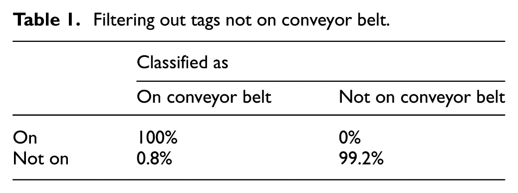
PRSS filters out those tags not on conveyor belt. Five static tags are placed near the conveyor belt and there are three people attached with five tags walking (about 1.5 m/s) around. After 50 experiments (
Filtering out tags not on conveyor belt.
Benchmarks
To further analyze the performance of PRSS, we perform several benchmarks. Usually, the aperture is 0.5 m length, the tag spacing is set as 10 cm, and the speed is 4 m/s.
The performance of three subsystems
The accuracy ratio of radial velocity-based sorting is shown in Figure 11(a). The speed of the conveyor belt and the tag spacing have great influence on the performance of radial velocity-based sorting. The descent of the tag spacing and the ascent of the speed both cause the decrease of interrogation times for a tag, that is, there are fewer velocity points to estimate the zero point time. Then, the phase curve fitting method is used to get a coarse-grained time

The performance of three subsystems (the horizontal axis shows the tag spacing, all tags are regularly placed): (a) the radial velocity-based method, (b) the phase curve fitting-based method, and (c) the advanced holography-based method.
Moreover, as aforementioned, the aperture points far away from the zero point are more likely to have more error. In an experiment, the zero point time is about 5800 ms, while there are some outliers of phase values as illustrated in Figure 12(a) (the tag is interrogated when it is static). Without the first two methods, these outliers cannot be filtered and the search scope is huge. From Figure 12(b), it is obvious that the single holography-based method cannot get the right result and the advanced holography-based method may not get global optimization. In PRSS, the noise caused by outliers is removed, and the accurate result is achieved with a small search scope, which is illustrated in Figure 12(c).

Holography-based method: (a) some outliers (<4000 ms), (b) with all data points (2567 ms), and (c) the holographic image of PRSS (5716 ms).
Different iterations
The simplified particle filter in the advanced holography-based sorting can decrease the computational burden effectively. The sorting result of the first iteration (0.1 m aperture) is inaccurate, while after five times iteration (0.5 m aperture), the accuracy is very high. The relative error is the difference between tag spacing 10 cm and the distance estimated by zero point times of two neighboring tags and the conveyor belt speed. As illustrated in Figure 13(a), after five iterations, the advanced holography-based method gets accurate results because this probabilistic method coherently utilizes all measurement phase values.

The accuracy of PRSS: (a) the CDF of advanced holography-based method after the first and the fifth iteration, (b) the CDF of advanced holography with different aperture length, and (c) different noise, multi-path, and material.
Aperture length
Different aperture lengths have different ambiguity in holography-based sorting. A longer aperture usually means more obvious difference in noise of different aperture points, which can be weakened by each other in coherent reconstruction. On the conveyor belt with the RFID portal, the aperture length is hard to be accurately adjusted. So, we change the transmission power of the RFID reader to adjust its interrogation zone. The sorting system with high transmission power will have longer aperture. As shown in Figure 13(b), a longer aperture length has a more accurate result. At the same time, due to much longer aperture, the read time for one tag with 30 dBm is almost double than that with 20 dBm. So is the computational burden. What is worse is the reader with 30 dBm has a large interrogation zone which contains a lot of tags not on the conveyor belt and will interfere other radio devices. So, our system sets the transmission power at 20 dBm and then the aperture is about 0.5 m long to achieve satisfying sorting results.
Different noise, multi-path, and material
Tag positions determine their trajectories. Irregular positions mean different tags have different zero point distances
Conclusion
In this article, we present a RFID-based sorting system PRSS for dense objects on high-speed conveyor belts with high accuracy. We take advantage of the output phase to calculate radial velocity and the phase curve fitting to estimate coarse-grained zero point time. Then, we reconstruct a holographic image to get fine-grained locations. The final process achieves a significant reduction of computational burden by a small search scope and particle filter. The algorithm parameters and performance are mathematically discussed. We implement PRSS and conduct extensive experiments to validate its effectiveness with COTS RFID devices. The experimental results show that PRSS achieves up to 97% accuracy on average in less than 60 ms delay when the tag spacing is 10 cm. Our future work will further improve the accuracy and real-time performance.
Footnotes
Handling Editor: Qi Han
Declaration of conflicting interests
The author(s) declared no potential conflicts of interest with respect to the research, authorship, and/or publication of this article.
Funding
The author(s) received no financial support for the research, authorship, and/or publication of this article.