
Abstract
The designs of highly scalable intelligent sensory application—Ethernet-based communication architectures—are moving toward the integration of a fault recovery and fault-detection algorithm on the automotive industry. In particular, each port on the same network interface card design is required to provide highly scalable and low-latency communication. In this article, we present a study of intelligent sensory application for the Ethernet-based communication architecture and performance of multi-port configuration which is mainly used in safety-enhanced application such as automotive, military, finance, and aerospace, in other words, safety-critical applications. Our contributions and observations on the highly scalable intelligent behavior: (1) proposed network interface card board design scheme and architecture with multi-port configuration are a stable network configuration; (2) timing matrix is defined for fault detection and recovery time; (3) experimental and related verification methods by cyclic redundancy check between client–server and testing platform provide comparable results to each port configurations; and (4) application program interface–level algorithm is defined to make network interface card ready for fault detection.
Keywords
Introduction
Intelligent sensory application for fault-tolerant system guarantees availability and reliability in the network connections. Redundant network in fault-tolerant configuration allows the user to maintain persistent sessions during system failure or a routing outage or change.
Timing matrix with fault-tolerant network interface is a new breed of intelligent network interface card (I-NIC). 1 Different redundant network interface hardware are available for fault-tolerant configuration; this article discusses a dual-port network interface card (NIC) with the embedded algorithm for high-performance and safety-critical systems. The hardware uses the dual Ethernet ports to handle the hardware fault or routing changes. To achieve high-speed data rates, the fault-tolerant NIC employs a processor to offload the processing load from the host processor. This allows for Ethernet port multiplexing, and dynamic port reconfiguration or switching is to switch the Ethernet port without host system consultation and information sharing.
Multiple-port systems are preferable in mission critical environment. The embedded algorithm allows for fault detection based on both hardware and software faults. Redundant physical layer (PHY) provides failover to a redundant network path. This type of failover technique is fast as failures can be detected at the physical link layer and by embedded algorithm, and a new route or tree is pre-located when a failure occurs.
An I-NIC, to support multimedia application, having high-performance processors along with software architecture has been developed.2,3 The applications of fault-tolerant networks are unlimited from server applications, financial transaction systems, data transmission in consumer electronics (e.g. Internet Protocol television (IPTV)), and automotive industry to safety-critical systems.
The rest of this article is organized as follows: section “Intelligent sensory application” outlines the intelligent sensory application, and section “Time domain matrix” gives the mathematical notations and equations. Section “Proposed system” describes the proposed system. Section “Algorithm” presents that hardware requirements for developing a dual-port fault-tolerant network interface card (DP-FT-NIC) for data speed up to 1 Gbps. Section “Simulation” describes that an embedded processor-based NIC with multiple ports based on commercial off-the-shelf (COTS) components. Section “Port configuration” explains data and port configuration by illustrated each blocks. Section “Related works” explains related works and availability requirement in mission critical networks. Finally, section “Conclusion” concludes the article.
Intelligent sensory application
Faults or problem causes are not always known, and the solution to rectify fault involves both hardware and software as the cause can be of any of the both. Network cable tester is a hardware used for cable fault testing, diagnostic, and performance; a laptop is another handy tool with proper transmission control protocol and Internet protocol (TCP/IP) software installed; and ping is commonly used command to test the network. However, these solutions involve human and are time-consuming and not applicable in mission critical networks.
Fault-tolerant network
In general, fault-tolerant network or “high scalable” network systems describe a computer system or network-connected architecture in such a manner that in a case a component fails or software error occurs, a redundant or secondary component or procedure can immediately take its place with no loss (ideally) of service in minimum time, without human intervention. 4
Fault tolerance capability can be attained in software, hardware, or both. In fault-tolerant networks, usually the hardware, network Switch, NIC, Ethernet ports are duplex. Data loss and fault-recovery times can vary with the fault-tolerant technique and hardware.
Network faults
It becomes hard to list all faults, but can be generalized in hardware and software faults. Software faults can range from software error or bug either in operating system (OS) or in embedded software of switch or router. A large number of data transactions which processor cannot handle can cause a temporary outage of communication. 5
Hardware faults can be malfunction of hardware in client or any other component (switch, router, and cable) in the network system or path. The NIC design presented is designed keeping in view the physical faults, which require digital processing techniques to locate the faults along with the distance information.
Safety-critical system
Existing systems are designed to be tolerant to only certain faults, and in certain conditions, trade-off exists between fault types and combinations.6,7
In general, safety-critical system which included fault injection technology is a way to investigate the fault-tolerance system. Different hardware- and software-based fault injection techniques are available to validate the performance of the fault-tolerant system. A fault-and-error automatic real-time injector (FERRARI) system is developed to inject transient errors and permanent faults for concurrent error detection and correction. 2
In detail, detection of cable fault relies on time-domain reflectometry (TDR) techniques to detect the open or short end along with some distance information.7,8 These faults can be injected manually or by controlled hardware. Most of the data are induced by time-series input as well as time-domain ingestion and analytics. For our Ethernet-based communication product, NIC hardware design presented is capable to handle the intentional dummy faults, injected for testing, and also to handle the large amount of traffic generated for fault injection, testing and keeping in view the real-world scenario.
Time domain matrix
Timing notation
We can measure the failure occur time (fo), first detection time (fd), and recovery completely time (rc). To explain the fault, failure occur, first detection, and recovery completely are described as following:
Failure occur (fo). Occurred failure at least time. In this article, failure occur is addressed such as poor network state due to disconnected network or transmission data error occurred via poor network communication channel.
First detection (fd). The validation time for failure or not. Since detection time means that time is from some failure occurred until detected the failure, the faster detection for the failure occurred, it can provide the higher reliable system. Note that, for detection to transmission data error, we use a cyclic redundancy check (CRC)-16.
Recovery completely (rc). The recovery time from failure, when a fault occurred. When some failure or error occurred, the system should be provided for higher reliable service by fault recovery. Hence, if a port was disconnected or data were compromised, the system should switch the two ports. Hence, for the higher reliable system, we have to detect and recover some fault as fast as possible.
Figure 1 shows the illustration of the time from failure occurs until complete recovery. Hence, for higher reliable system, we have to detect and recovery some fault as fast as possible by detection and two port switching.

Projection of failure and fault in timeline.
Timing equations
Theoretically, we can calculate the performance of the fault detection and recovery time using the measured fo, fc, and rc. Moreover, we can represent each performance as DT, ST, FO by fo, fc, and rc, and total performance was represented as TS (i.e. the time is from first failure occurred until recovery completely). DT, ST, FO, and TS are represented by equations (1)–(4) as follows:
Detection time (DT). Excepted the switch time from failover time (equation (1))

Switch time (ST). It is the time during switched multi-port (equation (2)). Especially, switch time means interconnection port exchanges similar latency

Failover time (FO). The failover time means the time from the failure occurred at least time until the recovered failure (equation (3))

where DT(x), ST(y), and FO(z) are the functions of DT, ST, and FO, respectively.
We can calculate the failover time through measured time from both failure occurrences and recovery completed time. It should be noted that transmission speed (i.e. TSO) degrades as the frequency of occurred failure. Thus, the transmission speed by the number of failures is induced in (equation (4))

For providing a high-reliability system, both ST (i.e. switch time) and DT (i.e. detection time) must be required as minimizing overhead. Therefore, in this article, we design the efficient algorithm to provide high reliability of transmission network system.
Proposed system
In this section, we present different fault-tolerant related products, especially the architecture of DP-FT-NIC available in the market was studied9,10 and analyzed thoroughly for development of DP-FT-NIC to match our performance needs for at least 5 years, the time for minimum replacement and when the spares run out.
It was observed that the COTS hardware is available to support gigabit Ethernet (GbE), peripheral component interconnect/extended (PCI/PCI-X), and processing power. The software platform, especially the algorithm, and associated test benches are not developed for embedded faults tolerant NIC. The system is designed in a modular block style, to replace it with new components of better performance, even though NIC can be replaced.
To evaluate the performance of the fault-tolerant system, it was desired to have an evaluation kit11,12 with the required hardware and software capabilities to handle the high data transfer rate and processing power along with software development tools and performance analyzers.13,14
For instance, IBM PowerPC 750GX/GL evaluation board, having IBM PPC750GX processor 12 and Tundra TSI10815,16 host bridge with supporting circuits and components as shown in Figure 2, was selected for the said purpose. The PPC750GX/GL is targeted for high-performance, low-power systems (2.5 W typical and 3.7 W maximum) that use a 60× bus.

A block diagram of IBM 750GX evaluation board.
On basis of the testing using the reference hardware, we were able to design a DP-FT-NIC which can achieve the fault tolerance for mission critical systems, as shown in Figure 3. The hardware design is capable to handle GbE communication and heavy workload.

A block diagram of the designed dual-port NIC with embedded processor.
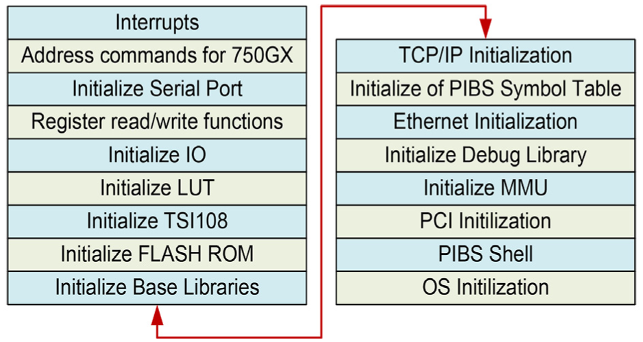
The design toolchain, IBM-embedded PowerPC operating system (EPOS), PowerPC initialization boot software (PIBS), and benchmarks tools 12 provided the entire necessary software platform to design, test, and evaluate the fault-tolerant algorithm with dual-port Ethernet as shown in Figure 4.

A block diagram of the designed dual-port network interface card with embedded processor.
For a cross development, the free Unix-style OS (GNU) toolset was build in Windows XP using Cygwin, which is a Linux–Windows converting utility (i.e. a way to run native Linux apps on Windows). The PIBS or basic input/output system (BIOS) initializes the processor, memory subsystem, device boot sequence, variable bus and clock speeds, and IP address designation for loading of EPOS. The EPOS consists of functions that are platform-independent such as kernel, TCP/IP protocol stack, shell command interpreter, and a PCI device manager using application programming interface (API) calls.17,18
Based on PIBS shown in Figure 5, by proper booting sequence, we can reduce the startup time and recovery from the power failure or hardware reset.
Initialization procedure during booting on the proposed system.
The “worst case,” when component is utilizing all of its resources, power requirement is shown in Table 1, the real values are lower than mentioned. 12
Worst-case scenario for power consumption of different components.
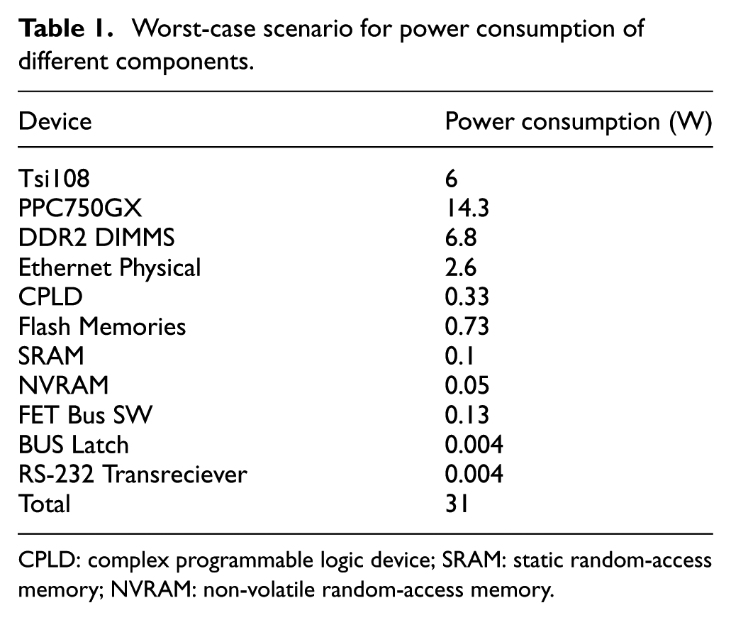
CPLD: complex programmable logic device; SRAM: static random-access memory; NVRAM: non-volatile random-access memory.
Each device does not work simultaneously together; however, the overall power consumption of difference components is calculated as 31 W, as shown in Table 1.
EPOS is written in C language and fully supports the C programming environment. The EPOS software offers IPv4 TCP/IP protocol stack with networking utilities. The networking utilities include arp, ping, ifconfig, netstat, route, dynamic host configuration protocol (DHCP), trivial file transfer protocol (TFTP), and dynamic name resolution client–server software. The building process of the toolchain is shown in Figure 6. The host PC can use the toolchain to load, test, verify, and benchmark the OS, APIs, and code.

Building process of the system toolchain.
The shell interpreter allowed the easy testing of the algorithm and different functions using the APIs, reducing the time in building up the software infrastructure.
Algorithm
The challenge lies in the design of fault-tolerant software to support the COTS hardware and complexity. Using the evaluation kit and different scenarios, we were able to design an algorithm at the higher level for the network consisting of DP-FT-NIC as shown in Figure 7, which can be extended for multiple-port FT-NIC. Each client has DP-FT-NIC, and two networks via Switch-A and Switch-B build redundancy among Client-1, Client-2, and Client-3.

Basic connection scheme for proposed algorithm.
We are investigated by the three steps: self-awareness, network awareness, and time-stamping.
Self-awareness
This section checks the connectivity between the two ports of the same DP-FT-NIC. It is necessary to evaluate the communication of the both Ethernet ports to be aware of any faults caused by losing connector, broken wire, no connection, and so on.
The EPOS simultaneously receives data through Port A and Port B as shown in Figure 8. To detect a fault, this system compares each other’s data. If two data have a difference, the CRC-16 method for Port A’s data is performed. The error of CRC-16 method means that Port A has a failure. The comparison and the restricted CRC-16 achieves reliability and a high speed.

Self-awareness scheme API-level code.
Network-awareness
Routing table, also called the forwarding table, may be built by the system administrator or by routing protocols. IP routing decisions are simple table look-ups. The two fields important for our current discussion are the destination and gateway fields. A routing table does not contain end-to-end routes. A route only points to the next gateway, called the next hop, along the path to the destination network.
To be network-aware, a message is broadcast to the entire network and all the listeners reply on the predefine port, which develops the routing table for the client. It is a lot of work for each machine that receives the broadcast packet; therefore, it was desired to have this once when the computer or NIC initializes or after recovery from the fault.
Using the routing table, IP address translations and domain name system (DNS) name device API functions; we can add and remove the route entries for deciding the path and alternate path in case a fault occurs as shown in Figure 9.
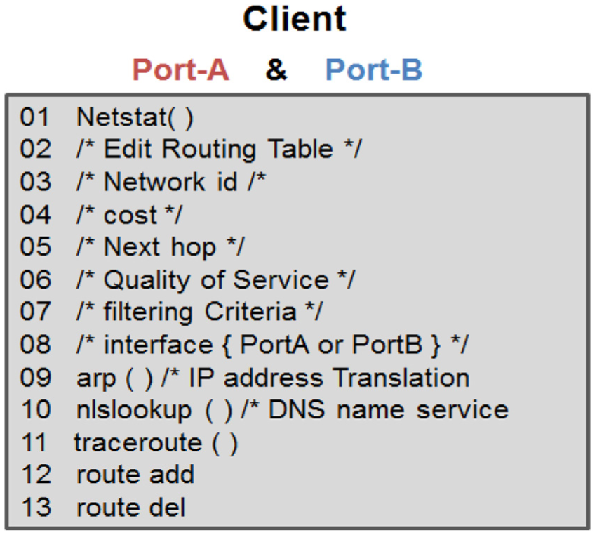
Network-awareness on the client side by modifying route entities for path.
Time-stamping
Time-stamps exchanged are used to determine individual roundtrip delays and clock offsets, as well as provide reliable error estimates. Clock differences such as local clock resolution and skew error need to be minimized; techniques such as in Baranski et al. 13 can be used for such purposes.
In practice, errors due to stochastic network delays dominate; however, it is not usually possible to characterize network delays as a stationary random process since the network queues can grow and shrink in the chaotic fashion and arrived customer traffic is frequently bursty.
As shown in Figure 10, a client broadcast a package to be received by all other clients, the reply contains the time information of that client. The receive packets from all the clients are used for computing the time of the day, delay, clock resolution, and so on.

Time-stamping scheme API-level code.
Simulation
In this chapter, we present a simulation result along with graphical user interface implementation. In order to evaluate our approaches for the higher reliable system, we make a software program using client–server model and test using real data set. Although this program was very simply implemented, it can provide higher reliability than the straightforward client–server program.
The program consists of two tasks, switching between the two ports and using disconnection and reconnection.16,19–21 For that, first, we can disconnect the network connection during the transmission data. Second, when some errors occurred in a port, it exchanges the two ports. Also, for the detection of the errors, we used the CRC-16 method, and it was performed at once when the difference exists in compared with two ports.
Especially, since CRC-16 was performed at once for the difference of the transmission data, it can be more efficiently performed in runtime than simple one. Figure 11 shows our implemented software program with client–server system.

(a) Screenshot of file transfer server on the proposed program and (b) booting sequences with CRC-16 check.
In Table 2, we confirmed the performance of total failure recovery time from the detection. In this software, the average time of fault time (i.e. the delay time for disconnect network) was 30 ms, and the time of recovery from detection error was 16 ms. Therefore, this system can provide higher reliable service in runtime with required less 50 ms at once fault.
Simulation results on client and server.

Also, when the larger data transmitted via poor network, it can reduce the degradation of the transmission speed (shown in Figure 12). For example, since fault recovery time was fixed to be less than 50 ms at one fault, smaller data transmission was degraded speed than larger data. However, the transmission data size was larger, the fault may affect negligible to the data transmission speed than smaller data size.

Comparison results by normal transmission and fault transmission.
Figure 12 shows the speed of the data transmission with increase in the data size (in this figure, x-axis is data size (MB) and y-axis is transmission data speed (bps)). As can be seen, as the data increase in “Normal Transmission,” which is normally transmitted, the “Fault Transmission” with fault/error occurs an almost similar data transmission rate as the data increases. In other words, it can be said that the performance of small amount of data is recovered from the large amount of data, and the performance becomes gradually the same. It should be noted that attention should be paid to the fact that as the data, not the small data size, gradually increase, the “Fault Transmission” becomes more and more close to the “Normal Transmission.”
Finally, we confirmed the performance of the CRC-16 method. Typically, with using CRC-16, we can guarantee the 16-byte data integrity during the transmission with using the 2 bytes. In our system, the average time for 1 Kbyte integrity was 28 ms. Furthermore, since CRC-16 was applied at once for the difference of the transmission data, it can more efficiently be performed in runtime than simple applying. Therefore, our system can provide both higher reliable and speed in runtime.
Port configuration
In this chapter, we also present a technical aspect of data flow with port configuration which will be available in various platforms, such as supercomputers and cloud computing system.
PHY provides the interface between the media access control (MAC) layer and the transceivers in GbE interface. The 1000BASE-X PHY also referred to as the GbE PHY consists of three major blocks, the physical coding sublayer (PCS), the physical medium attachment sublayer (PMA), and the physical medium dependent sublayer (PMD).
GbE uses all four cable pairs for simultaneous transmission in both directions. The data are transmitted over four copper pairs, 8 bits at a time, as shown in Figure 13.

Port-level data transmission and flow.
Most of the steps, each data processing unit is classified as a software-defined variables; however, each data are continuously transmitted to next data processing unit. Therefore, after the crossbar switch, each module is connected until the end of system.
Figure 13 shows the port-level transition and flow of data. It is distributed by crossbar to the Port 1, Port 2, … and Port n simultaneously and it goes to Ethernet controller and transmits and receivers. The PCS transmit and receive sections communicate with the physical media independent or dependent sublayers to transmit and receive data via magnetic and RJ-45 connector. Each clock generated from Ethernet controller finally goes to the end. Magnetics are like a transformer and are required at the high data transmission rate. High-performance analog-to-digital converter (A/D) and digital-to-analog converter (D/A) are needed to detect the cable faults using the TDR. This diagram is a specific knowledge required to multi-port configuration and large-scale data ingestion for intelligent sensory system.
Related works
Development of fault-tolerant system is closely related to fault testing techniques. Analytical modeling, experimental techniques, and fault and error injections techniques through which statistical parameters can be obtained for improvement and limitation analysis are already being developed and tested.
Moreover, CERN’s LHC accelerator (Large Hadron Collider at European Organization for Nuclear Research) used GbE and PCI-based I-NIC for error free data acquisition. 6 Owing to the criticality of data communication in above example scenarios, as well as in other seen or unseen future applications, fault-tolerant NIC promises reliable communication in multiple failure scenarios.
Using commonly available hardware and software, a fault-tolerant solution is developed for IP over Ethernet networks with no need for modification of existing networking equipment. 13
Molecular dynamics programs, 22 as well as examples of simulating the behavior of bimolecular systems, should look at the health of scalable networks in this article. At the same time, we have been able to influence the sensor-based system as a whole to have a more stable network as the size grows through the latest method of injecting the fault of the network.
Recently, we have confirmed the safety of new sensor-based systems through the publication of many research papers that require large amounts of data such as smart grid 23 or where autonomous navigation and sensory application is required through intelligent systems of vehicles.24–27
Moreover, in this article, a middleware-based fault-tolerant Ethernet connection is developed for process control networks with no change to COTS hardware and software and is transparent to IP-based applications achieving less than 1 ms end-to-end swap time and less than 2 s failover time. 5 Multiple-port NICs with the embedded processor, PCI port, and data storage capabilities are being developed by different companies,17,18,28–30 but still the existing embedded software needs to be upgraded to achieve the optimum fault-tolerance capabilities.
Conclusion
In this article, we present that a design of highly scalable intelligent sensory application which included Ethernet-based communication architectures, moving toward safety-critical application. This article defines the timing matrix required for fault detection and recovery, and this puts the constraints on the hardware required and embedded algorithm.
On basis of the testing using the reference hardware, we were able to design a dual-port NIC which can achieve the fault tolerance for mission critical systems. The hardware design is capable to handle GbE communication and heavy workload.
We have also defined the algorithm which can be embedded in the processor to achieve fault tolerance along with the data communication services, which is the prime task for NIC. The new algorithm is simulated using the CRC. API-driven algorithm, benchmarks, and related verification provide comparable results to synthetic workloads, but higher performance can be achieved with the specific low-level programming. In bottom line, the port configuration for multi-port NIC is shown, and this allows to perceive the hardware required and to implement the hardware as a single component.
Footnotes
Acknowledgements
The author thanks H Jabbar, who was a formal graduate student and now working as an assistant Professor, for a helpful drawing and simulation, and S Lee, who was a guest member while participated at Professor Jeong’s research laboratory, and now working as an assistant Professor, has a credit for this publication. This paper is appeared as a part of IMECS.
Handling Editor: Daniel Gutierrez-Reina
Author’s Note
The corresponding author is now working at CHA University, e-mail:
Declaration of conflicting interests
The author(s) declared no potential conflicts of interest with respect to the research, authorship, and/or publication of this article.
Funding
The author(s) disclosed receipt of the following financial support for the research, authorship, and/or publication of this article: This research was supported by Basic Science Research Program through NRF funded by the Ministry of Science, ICT (2017R1A2B4005517).