
Abstract
Multi-radio and multi-channel wireless mesh networks using directional antenna (MR-MC DWMN) greatly improve the spatial reuse of wireless channels and increase network capacity. However, the number of directional radio interfaces in MR-MC DWMN affects topology reliability and survivability. This article focuses on the construction of robust topology with radio interface constraints in MR-MC DWMN. Because of the limitation of the number of directional radio interfaces, we first formulate this topology optimization problem with directional radio interface constraints to be equivalent to establish k-connected topology with node degree constraints and then propose a robust topology construction algorithm with directional radio interface constraint. We define the link weight based on node degree and then use graph theory to construct the robust topology with node degree constraints. The proposed constructing robust topology with directional radio interface constraint can not only establish k-connected topology but also minimize the maximum node degree and meet the requirement of radio interface constraints. Simulation shows that constructing robust topology with directional radio interface constraint obtains less maximum node degree and average path length than existing k-connected topology control algorithms under the limitation of directional radio interfaces. Moreover, the constructing robust topology with directional radio interface constraint achieves better network performance than other algorithms.
Keywords
Introduction
A wireless mesh network (WMN) is a multi-hop communication infrastructure consisting of connected mesh routers to provide Internet access for mobile clients. It becomes a promising alternative for addressing broadband Internet access.1,2 In WMN, many design problems, have been studied, such as topology control, power control, routing, and channel assignment. The main problem being addressed in these studies is construction of effective topology, also referred to as the topology control problem.
Traditionally, topology control algorithms in a wireless multi-hop network operate in single-radio single-channel (SR-SC) and multi-radio multi-channel (MR-MC) architectures. In SR-SC architecture, each node has only one radio interface, and all nodes share one common radio channel.3–5 In this architecture, the objective of topology optimization is to improve network capacity by each node readjusting its transmission power, but the network capacity is significantly limited by nodal interference. 3 Therefore, to meet the ever-increasing demand for more bandwidth, the architecture of MR-MC is used in WMN, where each node is operated with multiple radio interfaces and can operate on multiple channels. MR-MC has already proven an effective approach for improving the network performance in recent years. 6 Many problems of the MR-MC architecture are already extensively researched,7–10 such as interference measurement and modeling, power control, topology control, channel/radio interface assignment, network planning and deployment, and joint optimization, but this research focuses on omni-directional antenna.
Recent studies in ad hoc networks have shown that directional antennas can significantly improve capacity relative to their omni-directional counterparts.11–13 Technical advantages of directional antennas include extended transmission range, low interference, and low transmission power, making them attractive for static and quasi-static WMN. These current studies in WMN using directional antennas have not, however, considered the reliability and survivability requirement of topology.
A few topology optimization studies consider both constructing robust topology in WMN using directional antennas and the constraint of the number of directional radio interfaces on each node. Although Dong and Bejerano 14 first proposed the importance of constructing the strongly connected network topology in MR-MC WMN using directional antennas and presented a method of constructing 2-connected topology, this research did not provide an extension or an ideal for constructing more robust topology, that is, k-connected topology (k ≥ 2). Moreover, many fault-tolerant topology control algorithms15,16 are suitable only to the wireless multi-hop network with omni-directional and have not considered directional antennas. For WMN using directional antennas, a key problem for constructing robust topology is solving the limitation of the number of radio interfaces for each node.
Therefore, this article focuses on the construction of robust topology with directional radio interface constraints (CRTICs) in WMN using directional antennas. We formulate this problem to be equivalent to establishing k-connected topology with node degree constraints in which the degree of any node does not exceed the number of available directional radio interfaces. In this article, we assume all mesh nodes have the same number of directional radio interfaces m and give an original topology derived via the maximum transmit radius of each node. Our objective is to find a k-connected subgraph with node degree at most m from original topology. We first analyze the difference of topology optimization for MR-MC WMN with omni-directional and directional antennas and present the problem description and formulation. Then, we present an algorithm of CRTIC. Meanwhile, the analysis of the proposed algorithm is presented, indicating our proposed CRTIC is able to minimize the maximum node for the constructed robust topology. The result shows that the proposed CRTIC achieves better topology and network performance than these state-of-the-art k-connected topology control algorithms.
The rest of the article is organized as follows. Section “Related work” summarizes the related works. Section “Problem description and formulation” describes the network model, the difference of topology optimization in MR-MC WMN with omni-directional and directional antennas, and problem formulation. Section “Algorithm of CRTIC” presents the algorithm constructing robust topology with k-connectivity and directional radio interface constraints. In section “Performance evaluation”, we evaluate the performance metric of graph-theoretic and network performance. Section “Conclusion” provides the concluding remarks.
Related work
In terms of constructing fault-tolerant or k-connected topology in WMN or MR-MC WMN, the existing algorithms can be categorized using omni-directional and directional antennas.
For omni-directional, Li and Hou 15 developed centralized Fault-tolerant Global Spanning Subgraph (FGSS k ) and localized fault-tolerant local spanning subgraph (FLSS k ) algorithms, which both guarantee k-connectivity when a unit disk graph (UDG) is k-connected. The FGSS k and FLSS k are min-max optimal. Miyao et al. 16 gave out a k-connectivity preserving algorithm with lower time complexity, called local tree-based reliable topology (LTRT). However, it guarantees k-edge connectivity only while not accounting for k-node connectivity. Li et al. 17 proposed the cone-based topology control (CBTC) algorithm. In CBTC, each node needs to link at least one node in every cone of degree a centered at this node. Meanwhile, they proved that it can preserve k-connectivity when a < 2π/3k. Guo et al. 18 proposed a centralized k-connected fault-tolerant topology control algorithm with particle swarm optimization (CKFTC-PSO), which considers both node failure and power efficiency. Based on CKFTC-PSO, we propose a distributed k-connected fault-tolerant topology control (DKFTC) algorithm with PSO called DKFTC-PSO. But this algorithm cannot guarantee the k-connectivity for the constructed topology. Gundry et al. 19 studied a fault-tolerant differential evolution-based topology control mechanism (TCM-Y). TCM-Y uses a Yao-graph-inspired fitness function to preserve a node’s minimum desired number of connections with its neighbors while uniformly dispersing mobile nodes in an unknown terrain. However, the TCM-Y requires at least k neighbors at all times. Bagci et al. 20 studied a scheme based on cooperative communication to achieve more efficient fault-tolerant topology control with k-connectivity. By exploiting the advantage of cooperative communications, it can achieve path energy efficiency and lower power consumption. Guo et al. 21 revealed that minimum total power does not lead to minimum interference.
In terms of using directional antennas, Kumar et al. 22 present a topology control approach using directional antennas in WMNs. This approach mainly solves the problem of preserving network connectivity when k directional antennas on each node are to be oriented. Similarly, Wong and Chan 23 present a joint optimization of topology control, routing, and channel assignment in WMN with directional antennas, and the results show that the proposed algorithm performs better than omni-directional in terms of loss rate, delay, fairness, and throughput. Zhang et al. 24 presented topology control with a minimal traffic delivery ratio from each node to the gateway nodes, and the results show that the number of antennas affects network performance; however, the constraint of the number for directional antennas is not considered. So, Zhang et al. 25 proposed a topology control algorithm in WMN with m directional antennas. In addition, Liu et al. 26 proposed a three-step solution to construct a logical topology to maximize the minimum delivery ratio of traffic demands of routers. The three-step solution includes a set of routing trees, assigning the radio interface of each node, and adjusting antenna orientations and assigning a channel to all links. However, these studies in WMN using directional antennas did not consider the reliability and survivability requirement of topology.
Related model and weight function
Model of omni-directional and directional antennas
Omni-directional antennas
An omni-directional antenna is a wireless transmitting or receiving antenna that radiates or intercepts radio-frequency electromagnetic fields equally well in all horizontal directions in a flat, two-dimensional geometric plane. For omni-directional antennas, each node generally has a single radio. Since each antenna corresponds to a radio on a node, we use antenna and radio interface interchangeably in this article. In Figure 1, all nodes have fixed transmission distance Rt. We consider one channel in the system, and communication links are bi-directional. If a node vi wants to transmit to its neighboring node vj, then all nodes in transmission distance Rt of node vi can receive the transmission information from node vi.

Transmission and reception of omni-directional antennas model.
Directional antennas
Antennas that offer enhanced performance in some directions, at the expense of other directions, are directional antennas or directional radiators. For directional antennas, we assume each node is equipped with m radios and each radio is associated with a directional antenna. Radios on the same node can be active at the same time. All antennas have the same beam width θ (mθ ≤ 2π) and are fixed after configuration. In Figure 2, in this antenna model, a node vi successfully receives a transmission from a neighboring node vj only if node vi’s receive beam points to node vj and no other nodes within node vi’s receive beam transmits in the same time slot.
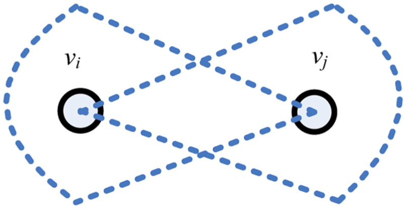
Transmission and reception of directional antenna model.
Network model
We consider WMN as an undirected physical topology graph G(V, E) comprising n wireless nodes V = {v1, v2, …, vi, vi+1, …, vn}; E = {eij} is the set of all links. The involved links are symmetric for simplicity. In other words, for vi, vj∈V in an obstacle-free environment, if there exists a link between them, then the channel is reciprocal. Each node has k radio interfaces attached to directional antennas and used for establishing point-to-point communication with adjacent nodes and the same maximum transmit power pmax, which is associated with the maximum transmit range rmax(pmax). Each directional antenna on the wireless node before updating network topology established a communication connection only with a directional antenna on another wireless node. Let d(vi, vj) be the distance between vi and vj. If d(vi, vj)≤r(pi), where r(pi) is the transmit range of vi with power pi (0 ≤ pi ≤ pmax), then a link eij exists from vi to vj. Meanwhile, we use the UDG—all nodes have the same transmit range—to represent all possible point-to-point connections. It is noted that UDG is topology derived via the maximum transmit radius.
Weight function
In this article, we define the LW(u1, v1) as the link weight of edges (u1, v1). The LW(u1, v1) = De(u)+De(v), where De(u) denotes the node degree of node u. To ensure different weights between any two edges, we use the ids of the nodes. 12 Specifically, given two different edges (u1, v1) and (u2, v2), the rules for comparing the weight value are defined as

If the ids of end nodes for each edge differ, each edge has a different weight. The meaning of id is the node number, such as the id of node vi is i. Therefore, the weight function will ensure the uniqueness when adding edges.
Problem description and formulation
In this section, we describe the difference of topology optimization for MR-MC WMN with omni-directional and directional antennas. Then, we present the problem formulation of constructing robust topology in MR-MC WMN using directional antennas.
Problem description
The types of directional antennas can be categorized as the traditional directional antenna, which is pre-fixed in a direction, and the smart directional antenna, which consists of three components—a radiating element, a combining or dividing network, and a control unit. The smart directional antenna also has two types—a switched beam antenna and a steerable beam antenna. 13 In this article, we mainly consider the directional antenna based on a steerable beam. This type mainly steers its radiating pattern either electronically or mechanically to focus on an intended direction. Moreover, according to the network model in sections “Model of omni-directional and directional antennas” and “Network model,” each directional radio interface on a node is paired with a directional radio interface installed on another node within transmission range to form a point-to-point connection before updating network topology.
Therefore, for MR-MC WMNs, the main difference of topology design in using directional antennas is that, because of the narrow beam of directional antennas, a node only generally communicates with another node. 19 For example, in Figure 3, we assume that each node has two directional radio interfaces. For the network using omni-directional in Figure 3(a), the node v1 can establish the connection with other nodes when node v1 increases the transmission power. However, for the network using directional antennas in Figure 3(b), if the node v1 communicates with other nodes, the number of other nodes connecting is limited by the number of directional radio interfaces on node v1.
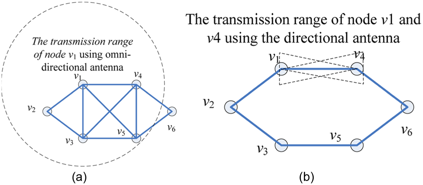
Example of covered range for omni-directional and directional antenna: (a) network with omni-directional antenna and (b) network with microwave directional antenna.
From the above description we know, in the network using a directional antenna, the number of directional radio interfaces determinates the number of links. In a practical network deployment, the number of directional radio interfaces is limited because of the cost of node device and the difficulty of scheduling directional radio interfaces. Therefore, constructing the robust topology in MR-MC WMN using directional antennas differs greatly from a wireless multi-hop network using an omni-directional antenna. The main problems are how to construct the robust topology with k-connectivity and the limitation of the number of directional radio interfaces in MR-MC WMN using directional antenna.
Problem formulation
The proposed CRTIC focuses on construction of topology with k-connectivity and the limited number of directional radio interfaces in MR-MC WMNs. The topology constructed must meet the k-connected requirement and limit the number of directional radio interfaces. Therefore, our objective is to find a k-connected subgraph with bounded node degree from the given initial graph. To solve the problem, we take network capacity as the optimization objective and use the k-connectivity of topology and the maximum number of radio interface as the constraint. The specific problem formulation is as follows

Subject to


where D(vk) is the node degree representing the number of directional radio interfaces, k is the specific value of the connectivity between any two different nodes vi and vj, and R(vi, vj) is the connectivity requirement between any two nodes for the constructed topology.
In the above problem formulation, the optimization objective of equation (1) is to maximize network capacity. In equation (2),
In Guo et al., 21 the topology control problem of finding the minimum-cost k-connected subgraph is proved as the nondeterministic polynomial time (NP) problem. Our optimization objective is equivalent to a minimum-interference problem. Adding these constraints of k-connected and the maximum number of radio interfaces, the solution of the proposed problem is also NP-complete. Therefore, in section “Algorithm of CRTIC,” we present a polynomial-time heuristic algorithm.
Algorithm of CRTIC
In this section, we develop the polynomial-time heuristic algorithm CRTIC. We first introduce the central ideal of CRTIC algorithm. Then, we present the main procedure of CRTIC and prove that CRTIC-phase 1 minimizes maximum node degree.
From section “Problem formulation,” the optimization is mainly to find a solution with the maximum network capacity such that it satisfies the radio interface and k-connected constraint. Our proposed algorithm consists of two phases, CRTIC-phase 1 and phase 2. In CRTIC-phase 1, we establish the robust topology with directional radio interface constraints based on weight function. In the second phase, we add the communication link at unused directional radio interfaces.
In the first phase, we mainly consider satisfying the directional radio interfaces constraint under the requirement of robust topology. We first solve the construction of the robust topology, that is, a k-connected topology needs to be constructed. According to graph theory, constructing a k-connected graph means to solve the k disjoint paths between any two nodes. Then, we attempt to solve maximum network capacity with the minimum number of nodal radio interfaces in solving the disjoint path. To achieve the objective, we exploit the minimum spanning tree (MST) algorithm, which can minimize the number of directional radio interfaces in the procedure of solving the k-node disjoint paths.
In the second phase, because of the minimum directional radio interfaces in the first phase, the used number of directional radio interfaces on some nodes for constructed topology is less than the m directional radio interfaces. Therefore, we add the link (vi, vj) when D(vi) < m, D(vj) < m, and d(vi, vj) < rmax(pmax). The objective of this phase is to increase the network capacity by adding the links.
The main procedure of the first and second phases are summarized in the following algorithms:
Initialization: Vis_flag(vi, vj) = 0, G′(V′, E′) = NULL, Ei = 0. While (G′(V′,E′) = NULL or Eiterations_num −Eiterations_num−1 > 0) Constructing the directed graph Gd (V′, E′) by topology decomposition operation in G(V, E) For each node pair (vi, vj)∈G(V,E) and Vis_flag(vi, vj) = 1 t = 0, Pd = Pt = ϕ For (t < k) Seeking an augment path Pt between node pair (vi, vj) using MST algorithm based on LW(G) in Gd (V′, E′) If Pt is not exist then t = k; else c(Pt) ← min(c(u, v): (u, v)is in Pt) f(u, v) ← f(u, v) − c(Pt) and f(v, u) ← f(v, u)+c(Pt) end if t ← t+1; Pd = Pd∪Pt End for G′(V′, E′) = G′(V′, E′)∪Pd Else Print(“No exist k-connectivity topology”) Exit End for Eiterations_num = |E′|, G(V, E) = G′(V′, E′) End while
For each node vi for G′(V′, E′) For each node vj in G′(V′, E′), where vi! = vj If D(vi) < I and d(vi, vj) < rmax(pmax) Adding the link (vi, vj) to G′(V′, E′) End for End for Gl(Vl, El) = G′(V′, E′)
To further understand the CRTIC algorithm, we provide the detailed description to explain each step in CRTIC-phase 1 and phase 2.
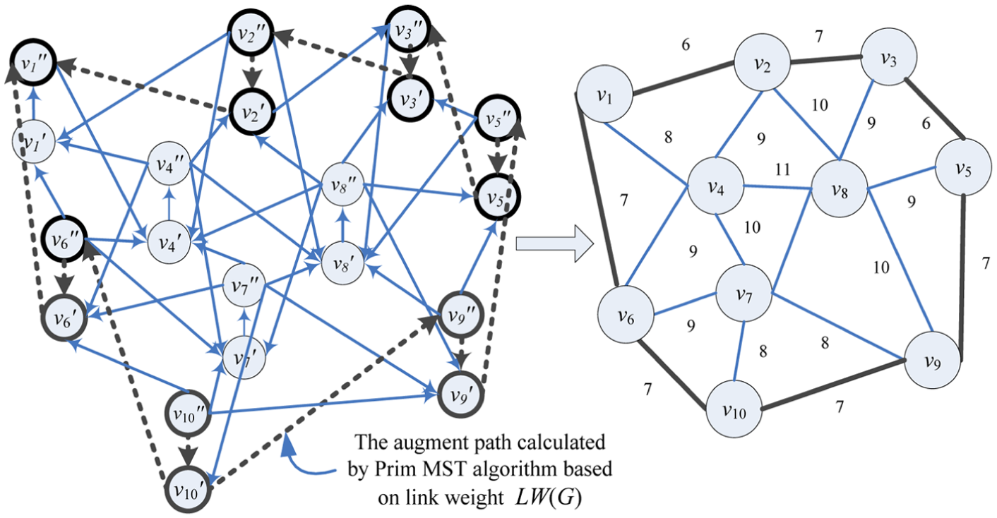
In CRTIC-phase 1, variables are initialized (line 1), such as Vis_flag(vi, vj) = 0, G′(V′, E′) = NULL. The variable Vis_flag(vi, vj) is used to mark whether node pair (vi, vj) is visited. The G′(V′, E′) is to store the output topology. For line 2, the established directed graph by topology decomposition operation is convenient to find the disjoint paths between any two nodes. The specific topology decomposition operation is shown in Figure 2. In Figure 4, each node vi is split into two nodes,

Constructing the directed graph Gd (V′, E′) by implementing a splitting operation.
Merging operation of augment paths in CRTIC-phase 1.
Output topology by CRTIC-phase 1.
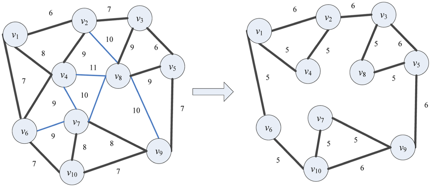
In CRTIC-phase 1, the optimization focuses on the minimum of maximum radio interfaces under the k-connectivity requirement, but it causes some nodes to use less than the given number of radio interfaces. In CRTIC-phase 2, our purpose is to add the link based on the given number of directional radio interfaces. For example, in Figure 7, when each node provides three direct radio interfaces, nodes v4, v5, v6, v7, and v8 only occupy two direct radio interfaces, indicating the optimization result of CRTIC-phase 1 cannot fully use the interface resources. Therefore, lines 1–6 in CRTIC-phase 2 check the number of interfaces occupied on each node. If the visited node and its adjacency node both exist in an unused interface, a link is added between the two nodes. When all nodes are visited, the final topology is stored into Gl(Vl, El) (line 7 in CRTIC-phase 2). The procedure of operation is shown in Figure 7.

Output topology by CRTIC-phase 2.
Analysis of CRTIC algorithm
Theorem 1
Given an initial network G(V, E), the maximum number of directional radio interfaces on node in G′(V′, E′) constructed by the proposed CRTIC-phase 1 is minimized.
Proof
From section “Problem description” as we know, we must prove that the maximum node degrees in final output topology G(V′, E′) is minimized, that is, min. max (De(v1), De(v2), De(v3), …, De(vi), …, De(vn)), vi∈V′. It is equivalent to min. max (De(NG(v1)), De(NG(v2)), De(NG(v3)), …, De(NG(vi)), …, De(NG(vn))), where NG(vi) denotes the adjacent nodes of vi. Then, it is also equivalent to prove the problem of min. max (De(v1), De(v2), De(v3), …, De(vi), …, De(vn))+min. max (De(NG(v1)), De(NG(v2)), De(NG(v3)), …, De(NG(vi)), …, De(NG(vn))). Therefore, if we can prove the problem of min. max(De(v1)+De(NG(v1)), De(v2)+De(NG(v2)), De(v3)+De(NG(v3))+…+De(vn)+De(NG(vn)), that is, min. max(De(vi)+De(NG(vi)), vi∈V′, we can conclude that the result is true. According to “Algorithm of CRTIC,” CRTIC-phase1 achieves the optimal topology by repeating the procedure of finding the node-disjoint paths set R between any two nodes. As we know from algorithm CRTIC-phase 1, in each iteration, the disjoint paths solved by MST use LW(vi, vj) = De(vi)+De(vj), where vj∈NG(vi). So, we transfer the proof of min. max (De (vi)+De (NG (vi)) to prove that the maximum of link weight in disjoint paths set R is minimized.
Now, we prove by contradiction that the maximum link weight for each node-disjoint path P in Gd(V′, E′) is minimized. Let T be the minimum span tree and P be an augment path between vx and vy, where P∈T and P∈R. Assume the maximum link weight in path P in Gd(V′, E′) is not minimized. Then, links e and e′ exist, where e∈E(T), e′∈E(G−T), LW(e′) < LW (e), and LW(P − e+e′) = LW(P) − LW(e)+LW(e′) < LW(P). Since P∈T and there is only one path between any two nodes in T, the number of paths between vx and vy is 1. Hence, LW(T − e+e′) = LW(T) −LW(e)+LW(e′) < LW(T) leads to a contradiction that the minimum span tree T is the minimum weight sum of all links. So, we conclude that this result is true.
Complexity analysis
We analyze the computational complexity of CRTIC. For a given G(V, E) with n nodes and m links, let the number of iterations be It. We use an adjacency list to store the network graph G(V, E). CRTIC mainly includes two phases. In CRTIC-phase 1, there are splitting operation and It iterations procedures. As we know from the CRTIC-phase1 algorithm, the computational complexity of the splitting operation is O(n+m). In each iteration, the k disjoint paths between two different nodes, vi and vj, must be solved. In the procedure for seeking the k disjoint paths, since the network includes n(n − 1)/2 different node pairs, the time of solving k node-disjoint paths is n(n − 1)/2. For each procedure of solving k node-disjoint paths, the augment path between any two nodes is found by the MST algorithm. If the graph G(V, E) is stored in the adjacency list, the complexity of the MST algorithm is O(m+n). After finding the augment paths, these paths are used to update the flow. The flow updating of each path in the worst case takes n − 1 times addition and subtraction operations, so the total time of finding the k augment paths is O(kn). The total computational complexity of CRTIC-phase 1 is, therefore, O(It2n(n − 1) k (m+n+k n)). In CRTIC-phase 2, each node is checked for whether the number of direct interfaces is less than the given number of interfaces and the number for adding the link (vi, vj) to G′(V′, E′) is D(vi) − m. So, the total time complexity of CRTIC-phase 2 is n(max (D(vi)) − m). From the above analysis, we know the total time complexity of CRTIC is O(It 2n(n − 1) k (m+n+k n)+n(max (D(vi)) − m)).
Performance evaluation
To demonstrate the effectiveness of the proposed CRTIC algorithm, the performance of average hops, average node degree, and maximum node degree is evaluated. MATLAB establishes the simulator of topology control. The 50 nodes are uniformly distrusted in 1000 × 1000 m2 regions. The transmission range of all nodes is 250 m. The parameter setting of simulation is shown in Table 1. We compare the proposed CRTIC with the state-of-the-art fault-tolerant algorithms, including UDG, FGSS, and LTRT. Figure 8(a)–(e) shows the topologies derived by UDG, FGSS, and LTRT; the proposed CRTIC-phase 1; and the CRTIC-phase 2.
Parameter setting of simulation.


Comparison of topology performance between proposed algorithm and other algorithms: (a) UDG topology, (b) constructed topology based on FGSS, (c) constructed topology based on LTRT, (d) designed topology based on proposed CRTIC-phase 1, and (e) constructed topology based on proposed CRTIC-phase 2.
Figure 8(a) illustrates that the maximum transmission distance of topology constructed by UDG is longer than that of other algorithms, which cause more connection with neighbor nodes. Owing to the limitation of the number of directional radio interfaces, many links cannot establish communication relationship between nodes. In Figure 8(b), the FGSS algorithm obviously reduces the node maximum transmission distance and the number of links. This algorithm first sorts all edges in ascending order of weight and then judges the k-connected between two terminate nodes of each edge in the order. If it is k-connected, the edge is inserted into an output topology graph. However, the FGSS algorithm does not consider the constraint of directional radio interfaces. The maximum node degree of the topology in Figure 8(b) is larger than the number of directional radio interfaces. Therefore, it also causes some links to not communicate with each other. For the topology derived by LTRT in Figure 8(c), the main contribution of the LTRT algorithm is an improvement of computational complexity. For our proposed algorithm CRTIC in Figure 8(d) and (e), since the CRTIC-phase 1 first minimizes the number of directional radio interfaces on node under the condition of meeting radio interfaces constraints, the maximum node degree of the topology in Figure 8(d) is smaller than that of other algorithms. Although two terminal nodes in each link can communicate with each other, the topology is not enough to use directional radio interfaces. Therefore, CRTIC-phase 2 makes up for the shortcoming in Figure 8(e), and the link is added between any two nodes of existing unused interfaces. For CRTIC-phase 2, the maximum node degree of the topology in Figure 8(e) is no more than the interface constraint m = 4. The related performance parameters of these topologies are listed in Table 2.
Comparison analysis of topology constructed by the proposed algorithm and other algorithms.

UDG: unit disk graph; LTRT: local tree-based reliable topology; FGSS: fast generalized subset scan; CRTIC: constructing robust topology with directional radio interface constraint.
As we know from Table 2, the proposed CRTIC algorithm can greatly decrease the number of average and maximum node degrees compared to other algorithms. It also indicates that the number of directional radio interfaces is minimized in CRTIC-phase 1. But the average hops in CRTIC-phase 1 are more than the average hops for other algorithms. However, this problem is solved in CRTIC-phase 2. From Table 2, when the interface constraint m is given, that is, m = 4, the average hops are less than LTRT and UDG, proving that the proposed algorithm CRTIC achieves the trade-off between average hops and direct radio interfaces constraints.
To further validate the CRTIC algorithm, we consider 50- to 100-node networks as simulation objects. These networks are established randomly in a 1000 m × 1000 m field. The transmission range is 250 m. We set two group k-connectivity requirements, 2 and 3 (Table 3), respectively, and the expectation numbers of directional radio interfaces are 4 and 6, respectively. Then, for these topologies constructed by UDG, the proposed CRTIC, LTRT, and FGSS; the performance comparison of the maximum node degree; average node degree; and average hops are presented. Results are shown in Figures 9–13.
Parameter setting of k-connectivity.


Average node degree under 2-connectivity requirement.
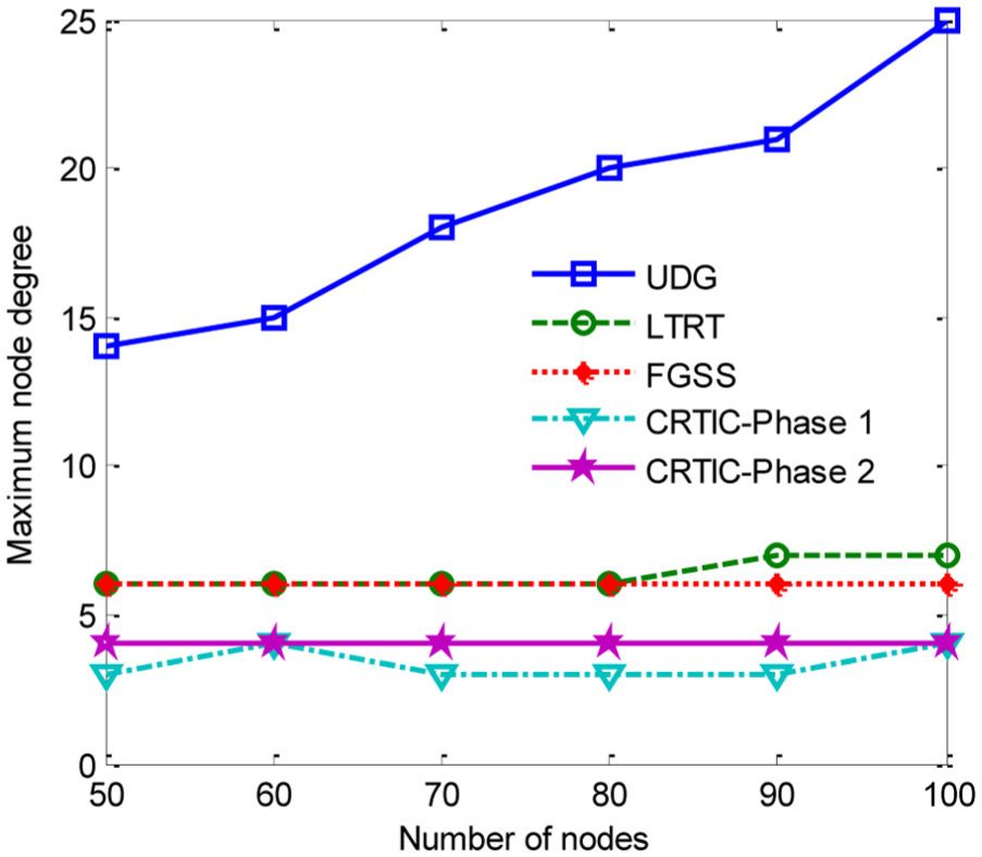
Maximum node degree under 2-connectivity requirement.

Average node degree under 3-connectivity requirement.

Maximum node degree under 3-connectivity requirement.

Average hops under 2-connectivity requirement.
In Figure 9, for the 2-connectivity requirement of the first group, the average node degree under UDG increases greatly when the number of nodes increases. However, the average node degree of other algorithms actually slightly decreases. The average node degrees of the proposed CRTIC-phase 1 and CRTIC-phase 2 are lower than that of FGSS and LTRT. Although the average node degree of CRTIC-phase 2 is close to that of FGSS, the maximum node degree is lower than that of FGSS and LTRT in Figure 10. Importantly, the maximum node degrees of CRTIC-phase 1 and CRTIC-phase 2 are both no more than the limited number of directional radio interfaces.
Similarly, in Figure 11, for the 3-connectivity requirement of the second group, the average node degree of the proposed CRTIC is lower than other algorithms, and the difference is more obvious than that in the 2-connectivity requirement of the first group. Furthermore, the maximum node degree of the proposed CRTIC in phase 1 and phase 2 in Figure 12 is not only no more than the constraint of the number of directional radio interfaces but also much lower than that of FGSS and LTRT. The average difference reaches to three. These results are enough to prove that the proposed algorithm CRTIC can meet the requirement for the limited number of directional radio interfaces under the same condition of topology fault tolerance. In Figure 13, the shortest path hops between any two nodes is analyzed. From Figure 13, the average hops of the proposed CRTIC in phase 1 are more than that of UDG, FGSS, and LTRT. However, CRTIC-phase 2 obtains smaller average hops. As we know, the more the path hops are, the longer the transmission delays are between two nodes. Therefore, the result of Figure 13 shows that the proposed CRTIC algorithm achieves the trade-off between network capacity and directional radio interface constraints.
In terms of network performance, we evaluate the performance of different algorithms by ns-2 simulations. The parameters are shown in Table 4. We consider networks of 50–100 nodes randomly placed in a 1000 m × 1000 m field. The transmission range and interference range are 250 and 450 m, respectively. Each node is equipped with four radio interfaces, and the available number of channels is 11. Moreover, 50 randomly selected source-destination pairs communicate using multi-hop routes, and we use a user datagram protocol (UDP) connection constant bit rate (CBR) flow for each node pair. The length of packet is 512 bytes and the sending rate of each CBR flow is fixed at 2 Mbps. All transmissions are unicast transmissions following the 802.11 media access control (MAC) protocol. The routing scheme is ad hoc on-demand distance vector (AODV) for the MR-MC WMN. We compare the performance by measuring the throughput and average end-to-end (E2E) delay with UDG, FGSS, and LTRT algorithms in MR-MC WMN using omni-directional antennas and directional antennas. Then, we present the network performance of our proposed CRTIC-phase 1 and CRTIC-phase 2. These results are shown in Figure 14.
Simulation parameters.
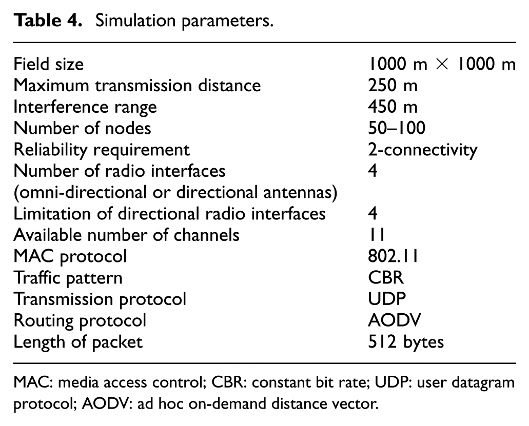
MAC: media access control; CBR: constant bit rate; UDP: user datagram protocol; AODV: ad hoc on-demand distance vector.

Comparison of network performance: (a) throughput and (b) end-to-end delay.
Figure 14 shows that in MR-MC WMN using omni-directional antennas, the throughput of CRTIC-phase 2 is higher than UDG, LTRT, and FGSS; meanwhile, its average E2E delay is the lowest. The network performance of CRTIC-phase 1 is close to that of LTRT and FGSS, but the node degree of CRTIC-phase 1 is smaller than that of the two algorithms. It means that when the minimum of radio interfaces is required, CRTIC-phase 1 is the best selection. When we consider the cost of network node or need to limit the number of radio interfaces, CRTIC-phase 2 provides better network performance than others. Meanwhile, in MR-MC WMN using directional antennas, since our objective requires the constraint of directional radio interfaces, and the topologies constructed by other algorithms do not meet the requirement, we only present the directional antenna network performance of CRTIC-phase 1 and CRTIC-phase 2. In terms of omni-directional and directional antennas, our proposed CRTIC provides better network performance than other algorithms. From Figure 14 as we know, since FGSS and LTRT consider neither the limitation of radio interfaces nor path length, it leads to the decrease in throughput and the increase in end-to-end delay. However, our CRTIC can not only meet the requirement of robust topology but also achieve better network performance under the limitation of directional radio interfaces.
Conclusion
We investigated the problem of constructing robust topology with radio interface constraints in an MR-MC WMN using directional antennas and proposed a CRTIC algorithm to achieve the optimization problem. The proposed CRTIC algorithm includes two phases. CRTIC-phase 1 first considered the minimum of maximum node degree under limitation of radio interfaces; CRTIC-phase 2 then improved the network capacity by checking the unused radio interfaces on each node and adding the link. By the MATLAB and ns-2 simulations, our proposed CRTIC algorithm has better performance than state-of-the-art k-connected algorithms regarding maximum node degree, average node degree, and average hops. Moreover, the simulations showed that CRTIC further improves the throughput and reduces the end-to-end delay.
Footnotes
Academic Editor: Yingtao Jiang
Declaration of conflicting interests
The author(s) declared no potential conflicts of interest with respect to the research, authorship, and/or publication of this article.
Funding
The author(s) disclosed receipt of the following financial support for the research, authorship, and/or publication of this article: This research was supported by the National Natural Science Foundation of China (Grant No. 61401189 and 61561035), the Natural Science Foundation of Jiangxi, China (Grant No. 20161BAB212036 and 20151BAB207039), the Natural Science Fund of Nanchang Institute of technology (Grant No. 2014KJ016), and the Science and Technology Research Project of Jiangxi Provincial Education Department (Grant No. GJJ151115).