
Abstract
Bluetooth low energy is an almost ubiquitous technology currently embedded in billions of power-constrained Internet of Things devices around the world. The Bluetooth mesh profile, released by the Bluetooth Special Interest Group in July 2017, allows Bluetooth low energy devices to form a mesh network, further enabling smart home and building applications where long-range connectivity is required. However, the current release of Bluetooth mesh profile still has power and deployment constraints that limit its applicability. To explore the viability of Bluetooth mesh profile in home/building automation applications, we built the Smart Doorbell: a proof-of-concept Bluetooth mesh profile–based visitor notification system for office spaces. The Smart Doorbell was implemented using a mesh network topology with nodes distributed across office building floors, serving as a real Internet of Things deployment and as a testbed for mesh network protocols. Similar Bluetooth mesh profile evaluations found in literature use mostly development kits and/or synthetic traffic in artificial settings; we contribute by using the Smart Doorbell, a system as close as possible to a minimum viable product, to evaluate power consumption and responsiveness as a proxy for product viability. This article presents the architecture of the Smart Doorbell, the viability evaluation results, and a direct comparison with FruityMesh, a competing Bluetooth low energy mesh network protocol. Overall, the fact that Bluetooth mesh profile devices can directly communicate with a user’s mobile phone (using Bluetooth low energy) considerably eases deployment and provisioning. However, the use of flooding to forward messages across the mesh network increases power consumption, precluding the use of battery-powered nodes on the network’s backbone and severely limiting the applicability of Bluetooth mesh profile in building automation.
Introduction
Since the advent of Bluetooth low energy (BLE) in 2010, battery-powered resource-constrained devices have been able to seamlessly integrate into the Bluetooth ecosystem and communicate with smartphones, tablets, and computers. BLE, now a standard feature in products ranging from wearables to home appliances, is becoming ubiquitous and by the end of 2021 an estimated 4.5 billion new devices shipped with BLE support. 1 However, BLE’s network star topology limits its usage to mostly point-to-point applications such as activity trackers and wireless headphones. Applications that require long-range connectivity and a robust network with path diversity, such as home and building automation, are typically implemented using a mesh network technology such as Zigbee, Z-Wave, Insteon, and others. Aiming to compete in these markets, the Bluetooth Special Interest Group (SIG) 1 released in July 2017 the Bluetooth mesh profile (BMP) specification: a new mesh network protocol based upon BLE.
Running a mesh network protocol on top of the BLE stack has been an active topic of research in the academic community and in industry due to the maturity of BLE and the installed base of billions of devices. 2 A BLE mesh network could potentially facilitate the deployment of large robust networks of BLE devices in home, office, and industrial spaces, enabling smart environments that natively interact with a user’s personal computing device. Because of the potential of this technology, several experimental and commercial mesh network protocols on top of BLE were tested and rolled out before and after the official Bluetooth SIG release.2,3
Mesh network technology for resource-constrained devices requires compromises, among the most impactful design choices is the multihop paradigm: routing or flooding.2,4 With routing, network nodes use a routing protocol to forward messages whereas, with flooding, nodes broadcast messages to propagate them. BLE mesh implementations such as FruityMesh 5 and BLEER 6 use routing, the official Bluetooth SIG release and CSRmesh 7 use flooding, and Bluetooth Now uses both. 4 The academic consensus is that flooding trades higher power consumption for lower end-to-end delay and network simplicity. 3
The decision to use flooding in the first release of BMP limits the applicability of this technology. Exploration of these limitations is currently a research topic in Internet of Things (IoT) and the main objective of this article. Whereas most research on this topic is focused on characterizing BMP’s power consumption, latency, and packet delivery rate (PDR) using a laboratory setting, a test network, and simulations, we contribute with a real smart building application using in-house manufactured nodes based on Nordic’s popular nRF52832 chipset and stack.
We presented our first prototype of a smart building application using BMP, the Smart Doorbell, with preliminary PDR results and a basic power consumption analysis in Martínez et al. 8 In this article, we go further with a practical analysis of our final prototype, specifically our experience with provisioning and deploying, responsiveness, and a more thorough power profiling of our network. In addition, we re-implemented our Smart Doorbell application using FruityMesh, a routing protocol over BLE, to compare the effects of both multihop paradigms on power consumption and responsiveness. While the Smart Doorbell in itself is not a novel implementation, the novelty of this work lies in the fact that, as far as we know, we provide the first evaluation of BMP using a complete working prototype of a smart building application (see Table 1). Figure 1 illustrates a graphical abstract of the steps taken to accomplish this and the organization of this article.
Overview of Bluetooth Mesh systems characterizations found in literature.
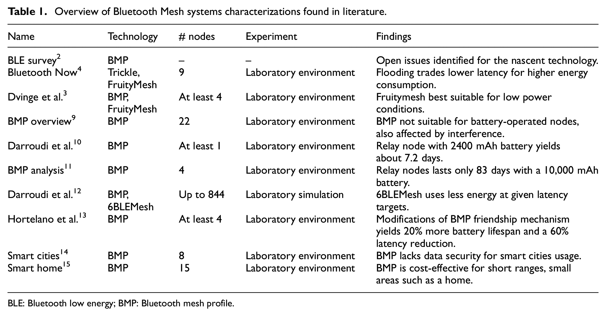
BLE: Bluetooth low energy; BMP: Bluetooth mesh profile.

Steps and architecture of the paper.
In section “Related work,” we summarize what has been done to characterize Bluetooth Mesh so far; in section “Methodology” we begin describing our system and specify our experimental methodology to characterize our system; and in sections “Results” and “Discussion” we present and discuss our results.
Related work
The market’s pressure to have a viable mesh network technology on top of the BLE stack prompted the release of several academic and commercial solutions years before the official release of the BMP in 2017. Darroudi and Gomez 2 performed a comprehensive study of these pre-release technologies in 2017; they highlighted the performance compromises between the routing and flooding multihop paradigms and motivated the need for a standard release.
Similarly in 2017, Murillo et al. explored the question of whether the then-upcoming BMP standard should be flooding or routing and proposed a hybrid solution that supports both paradigms: Bluetooth Now. 4 This work compared Trickle, 16 a flooding protocol, and FruityMesh, a routing protocol, before BMP was released. The work on FruityMesh by Dvinge et al. 3 is later presented as a potential candidate for replacing BMP when off-grid networks are a must and messages are not time-critical.
After the release of BMP, Baert et al. 9 presented the first thorough performance evaluation of the standard. They constructed a testbed network of 22 nodes in an entire building floor, then stress-tested the network with synthetic high-throughput traffic while exposing it to cross-technology interference. They concluded that the technology is not suited to implement networks consisting solely of battery-operated nodes and its performance is affected by cross-technology interference.
In 2019, Darroudi et al. 10 presented a complete study of energy consumption in a BMP network. Their main conclusion concurs with previously published work by estimating that a battery-operated relay node will have a battery life of about 7.2 days, limiting this technology to applications where the network backbone is appropriately powered.
In 2020, Hernández-Solana et al. 11 explored the capabilities, features, and limitations presented by BMP through an analytical approach. They provide several configurations that could potentially improve the network performance and reduce power consumption. However, it concludes underscoring the insufficiency of relay nodes in a real network deployment, lasting only 83 days with a 10,000 mAh battery.
In 2020, Darroudi et al. presented a comparison between a BMP network and 6BLEMesh, an IPv6 mesh network. They evaluated both technologies focusing on features such as energy consumption, robustness, and latency. Overall, 6BLEMesh performed better when more nodes are available and consumes less energy when certain modifications to latency are made; BMP was more resilient to topology changes. 12
In 2021, Hortelano et al. 13 proposed an improvement to reduce both power usage and transmission delays for low-powered nodes, by making changes on the original BMP friendship mechanism. Their modifications achieved a 20% increase in battery lifespan, around 2.5 months extra for low-powered devices, and a 60% reduction in message latency.
Other studies, such as in Veiga and Abbas, 14 where a framework for smart cities using BMP is proposed, and in Wan and Liu, 15 where a prototype for a smart home application with BMP is tested, do not study the performance of their networks and are based solely on development kit nodes.
Whereas the performance studies of Baert et al. and Darroudi et al. are fairly conclusive, they use development nodes in test networks with synthetic traffic. We contribute with a study of a real BMP network deployment in a proof-of-concept smart building application by (1) evaluating the system’s power performance and responsiveness and (2) evaluating the effect of BMP’s flooding paradigm by measuring power and responsiveness in a mirror FruityMesh implementation. To have a system as close as possible to an actual commercial product, we developed our own network nodes and two Android Apps, one to provision and another to interact with the network. Our nodes use the Rigado BMD-300, a BLE module based on the nRF52832 (System on Chip) SoC, because of its capability to support both mesh network protocols: BMP and FruityMesh.
Methodology
System description
Our system, the Smart Doorbell, started as an internal need in our office building as all hall doors require special card keys for access. Unannounced visitors will usually linger in the halls, waiting for us to notice them and open the door for them. What if we installed a button/bell in every door that when pressed will broadcast a message to our phones? Running with this idea, we started with a run-off-the-mill WiFi IoT button prototype, but the device was unreliable and impractical as it needed good WiFi coverage to properly function in every door. We realized that we needed a low-cost small-form-factor battery-operated device that could be simply glued to a door frame and function as a doorbell without much configuration and maintenance. Bluetooth Mesh seemed to be a good candidate technology for this; the available SoC solutions were relatively low-cost and power-efficient, plus deploying a building-wide Bluetooth Mesh network presented the opportunity for other interesting applications such as indoor navigation.
Figure 2 illustrates the main use case of the Smart Doorbell: a visitor reaches a locked door and presses a doorbell placed next to it; the doorbell sends a notification through the mesh network and starts blinking yellow; the notification is forwarded to the phones of all subscribed building employees; an employee that wishes to receive the visitor responds to the notification and heads to the door; upon receiving the response, the doorbell starts blinking green signaling that someone will come to open the door. If no one answers the notification, the doorbell will eventually time out and blink red signaling the visitor to press it again.

The Smart Doorbell is a simple visitor notification application: (1) a visitor reaches a locked door and presses the Smart Doorbell device, (2) the device starts blinking yellow and sends a notification, (3) staff members in the building receive the notification on their phones, (4) a staff member replies affirmatively to the notification, (5) upon receiving the reply the Smart Doorbell starts blinking green, and (6) the staff member receives the visitor.
Aiming to test the feasibility of this application, we deployed a Bluetooth Mesh network on the second floor of our building to provide coverage to an area of approximately 1000 m2: 2 hall doors, 3 laboratories, and offices for around 10 employees. All network nodes are based on the nRF52832, a Bluetooth 5 and Bluetooth BMP SoC developed by Nordic Semiconductor, with the Rigado BMD-300 as the controller. Except for the gateway, our nodes were designed and manufactured in-house; the hardware design is described in our previous work. 8
The firmware in each node uses the Softdevice version 6.1.0, a precompiled binary of the BLE stack, developed by Nordic Semiconductor. In addition, it uses the BMP SDK version 2.2.0 and the BLE SDK version 15.0.0. Nodes in our Bluetooth Mesh network can have one of three roles (see Figure 3):
Client node: This is a doorbell, it has a button and three LEDs for feedback and can be powered by either a 220 mAh coin cell battery or a rechargeable Li-ion battery. These nodes are the only battery-constrained devices. They are the only nodes in the network that can publish messages (when the button is pressed) by user interaction.
Server/gateway node: This is the network gateway in our application, powered by a USB/UART connection to an external computer. The server node holds a key-value pair table with the id of the client as key and its NOTIFICATION state as value. This table starts empty and grows when a new client node is added to the network. This allows the scaling of the application by avoiding to manually configure the server node in BMP. In our system, the server node forwards all client messages via UART to the external computer where they are processed and resent to a MQTT broker for redistribution.
Relay node: It receives and re-transmits every message from other nodes if they are on its radio reach. These nodes are used to expand the network coverage and to provide path redundancy.
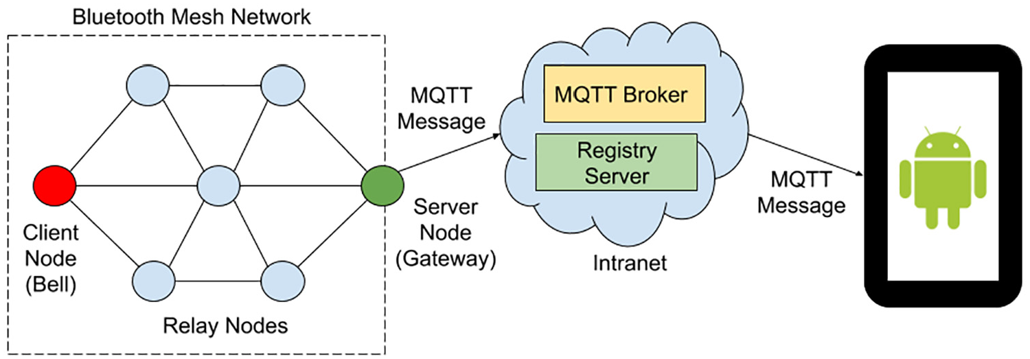
The Smart Doorbell’s Bluetooth Mesh network is composed of client nodes (the doorbells), a server node (the gateway), and relay nodes.
For BMP we used a maximum of 6 nodes; for FruityMesh, 4. The doorbell and gateway nodes are deployed in fixed positions, about 16.50 m apart. Using FruityMesh, with no relay nodes, doorbell and gateway nodes are too far away from each other to communicate. The operation of the Smart Doorbell system can be divided into three main elements: a notification app for our building staff, a network provisioning app for network deployment, and the client–server communication model within the mesh network.
Notification app
The Notification app, an Android app developed in-house, allows users (building tenants) to receive notifications on their smartphones when a visitor presses one of the doorbells on the hall doors. The app allows a user to subscribe to a specific doorbell by scanning a QR code sticker placed near each device (Figure 4). The QR code contains the network address of the doorbell in the mesh network; this address is used as a topic by a MQTT broker on our building intranet. After scanning the QR code, the Notification app subscribes automatically to that MQTT topic and displays a status bar notification every time it receives a message from the broker, allowing the user to reply either with Accept (indicating that they will receive the visitor) or Ignore (Figure 4). As soon as an employee replies accepting the message, the notifications will disappear in every smartphone subscribed to that doorbell as the reply is published to the same topic in our MQTT broker.

The Smart Doorbell is shown here with its 3D-printed case glued on a door frame and next to its QR code. A brief instruction sheet is also provided for visitors. As the doorbell is pressed, an alert is immediately shown on a user’s Notification app.
Client–server communication
Bluetooth Mesh defines the roles of server and client for communication at the application layer. A server maintains a state (e.g. light ON/OFF) whereas a client can query or change that state (e.g. a light switch). In our application, there is only one server node and it maintains the NOTIFICATION state for each client which is initially set to OFF. Every doorbell is a client node and for our network prototype we built two doorbells, one for each hall door. The client node has three visible LEDs (one green, one yellow, one red) and one button. When the button is pressed, the client node blinks yellow and sends a SET NOTIFICATION ON message to the server node. The server node, functioning also as a gateway to our building Intranet, receives the message, changes the NOTIFICATION state to ON, and publishes a MQTT message via its WiFi interface to the corresponding topic on our Intranet’s MQTT broker. This message is then viewed as a notification in the Notification apps in user’s smartphones (Figure 5).

State diagram of the events occurring on both the Client and Server nodes when the visitor presses the doorbell, until a staff member replies affirmatively to the notification generated, or the timer expires.
The NOTIFICATION state is set back to OFF either by the client node when it times out (blinks red) or by the server node when it receives a notification reply from a Notification app user. After sending the message, the client node polls the server continuously for a change in the NOTIFICATION state and blinks green if the change is detected. In this manner, the client node lets visitors know that notification of their presence has been sent (blinks yellow), someone has answered the notification and will come to the door (blinks green), or there was no reply (blinks red).
Network provisioning
Network provisioning consists of configuring a device so that it can join an existing Bluetooth Mesh network with a specific role. This process requires the use of a device with the role of provisioner. The provisioner scans the network, connects to a device, and reconfigures the device over the air. The provisioning process, for the Nordic modules in our solution, can be done by a hardware device or a smartphone app. Initially, we used a hardware device to provision our nodes in the first prototype of our system. 8 However, this method was quite cumbersome as network configuration parameters and roles are defined in the provisioner’s firmware; if a reconfiguration was needed, the provisioner had to be reprogrammed before proceeding. In June 2018, Nordic released an Android and iOS provisioner app that leverages the fact that most smartphones can connect, with Bluetooth versions 4.2 and higher, directly with a BLE device, through Generic Attribute Profile (GATT) bearer. This provisioning method is quite convenient as nodes’ roles’ parameters can be easily edited within the App and then flashed over the air to the target node. As stated by Bluetooth SIG, 1 roles cannot change once a node joins the network; if needed, the node has to be reprogrammed, reprovisioned, and finally, reconfigured.
We modified Nordic’s nRF Mesh App for Android to serve as our network provisioner. Our provisioner App sends a JSON-encoded notification to an internal registry server every time a new device is configured to join our Bluetooth Mesh network. If the new node is a client, the registry server generates a QR code with the node’s name and network address. This QR code is then printed and placed next to the doorbell/client node to allow users to subscribe to that doorbell using the Notification app.
FruityMesh implementation
For comparison purposes, we implemented a version of the Smart Doorbell that uses the FruityMesh protocol instead of BMP. FruityMesh 5 was born around 2015 as the first open-source implementation of a mesh network on top of the BLE stack. It was designed to build a network with battery-powered devices, trading-off lower power consumption for higher end-to-end delay. Unlike BMP, it is a connection-based routing mesh protocol.
FruityMesh runs on the nRF52832, therefore it was possible to migrate the Smart Doorbell to FruityMesh by simply reflashing our installed nodes. As with BMP, a FruityMesh device has to be given a network ID, a network key, and a unique node ID for it to join a network. In FruityMesh, this process is called device enrollment (analog to provisioning in BMP). A device can be enrolled by any other node, unlike BMP where the provisioner is a single node. Once part of the network, a device is called a node.
Once powered, and before beginning with the enrollment process, FruityMesh devices have to first discover each other by entering what is known as the discovery state. In this state, a device sends special broadcast messages called JOIN ME, which carry the metadata of the device. The discovery state itself has three modes, alternating the frequency in which they broadcast the JOIN ME packages and scanning windows. A graphical overview of the discovery state and modes can be seen in Figure 6.

The three discovery modes in FruityMesh: High, Low, and Off. High and Low have different JOIN ME package broadcast frequency and scanning windows. Off is a low power mode with advertising and scanning disabled.
Upon receiving a JOIN ME message from a neighboring node, a device decides to connect to it based on network parameters within the message. Once connected, the device starts the enrollment process and securely joins the FruityMesh network. Once enrolled, the device enters again the discovery state to detect and enroll any other orphan device in the vicinity. If they are no more orphan devices, the enrolling algorithm switches the discovery state of all nodes in the network to Low mode. A more detailed description of this process can be found in M-Way Solutions description of the FruityMesh protocol. 17
As soon as all network nodes are turned on, they will be on High discovery mode to form a network as quickly as possible. Because we know the exact number of nodes in the network, we configured them to disable discovery (to stay on the Off mode) once all of them are part of the network. If one of them is missing from the network, they all return to a High mode. This could happen, for example, when a node’s battery becomes depleted.
For the present work, we used the latest FruityMesh 5 protocol version usable for the Rigado Evaluation Board, version 0.8.8. M-Way Solutions, the company behind FruityMesh, provides both the firmware binaries and the Softdevice for the nRF52832. The softdevice is a precompiled binary for BLE management.
We built the Smart Doorbell system to evaluate the viability of BMP in building automation applications. We focused on two viability factors: power consumption and responsiveness. Power consumption determines the lifetime of battery-operated devices on the network and responsiveness affects the usability and acceptance of the system by its users.
Responsiveness characterization
System responsiveness is an aspect of user experience that is directly affected by the network mesh technology. User experience deals with questions such as: Does the user feel that it is easy and efficient to get things done with the system? An unresponsive system, for example pressing the doorbell and nothing happens, causes frustration and negatively affects the user experience. From the point of view of the system maintainers, users, visitors, and building tenants, the following metrics can be used to measure responsiveness:
Request time: The time in seconds from pressing the doorbell to receiving a notification alert in the Notification app. This is the sum of the time it takes the notification message to travel from the client node to the server node via the mesh network and then from the gateway to the smartphone via the MQTT broker in our intranet (illustrated in Figure 7(a)).
Reply time: The time in seconds from pressing “Accept” in the Notification app to blinking green in the doorbell node. This is the sum of the time the notification reply takes to travel from the smartphone to the gateway via the MQTT broker and the time it takes for the client node’s polling to get the status from the server node. Illustrated in Figure 7(b), with the polling actions in blue for Figure 7.
Connection time: Time measured only for FruityMesh devices, from the moment it is turned on until it gets accepted in a mesh network. This was measured with a Power Profiler Kit (PPK) from Nordic Semiconductor. 18 Illustrated in Figure 7(a) with the red arrows.
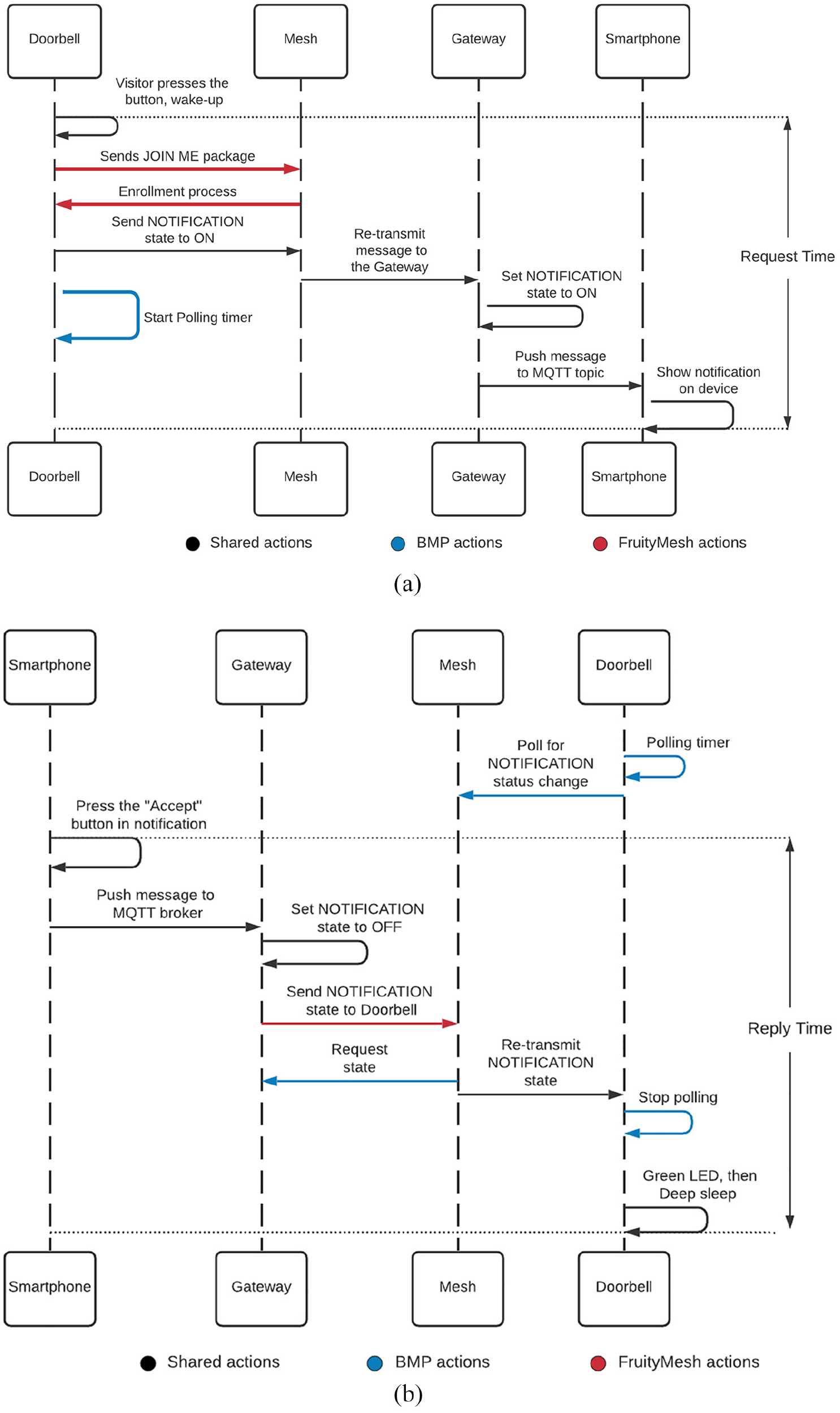
Responsiveness of the system. Different colors represent different actions per technology. For both technologies the request and reply time are measured with a smartphone timer. The connection time is measured for the FruityMesh doorbell only, with the Power Profiler Kit. (a) Request time. In red FruityMesh connection time, in blue BMP polling actions. (b) Reply time. In red FruityMesh event, in blue BMP polling actions.
Using a smartphone timer, we measured request time from pressing the doorbell to receiving the corresponding notification on the smartphone’s screen. Likewise, the reply time is measured from pressing the notification button “Accept” on the smartphone to blinking green on the doorbell node.
To isolate the request and reply time and eliminate, as much as possible, latency coming from outside the mesh network, we deployed a MQTT broker that is used exclusively for the Smart Doorbell application. Moreover, the building’s intranet was relatively uncongested during testing. Therefore, we can safely assume that time delays caused by the broker and the Intranet are both negligible and constant. Consequently, the average and variability of both request and reply time are mainly caused by the transit through the mesh network. Both time measurements are a form of latency and are affected by several factors in BMP, in our system we identified node density, client polling period, and client power configuration as the three most important factors. For node density, we used the number of relays as a proxy for node density. We varied the number of relay nodes, starting with the maximum amount of relays at our disposal up to no relays (the network only has the client node and the gateway, which are at fixed positions 16.50 m apart from each other). Each time a relay node is disconnected from the mesh network, the average distance between nodes increases. For BMP, after finding the most cost-effective node density (best compromise between responsiveness and number of relays), we varied the polling period of the client node and the deep-sleep configuration. For each combination, we performed 30 measurements of reply and request time to get an acceptable estimation of the average and variance of both variables.
Power measurements
Power consumption is one of the most important aspects to consider in mesh network applications for home and building automation. This aspect determines whether network nodes can be battery-powered and if so, the expected life of their batteries. This has an impact on the viability of the mesh network solution as some environments lack easy access to the power grid and therefore require battery-operated nodes with average battery life in the range of months or years. In order to optimize battery life, the nRF52832 SoC provides a deep-sleep mode. Enabling deep-sleep functions in the nRF52832 SoC reduces the amount of current the chip needs to function while idle, but at the cost of increasing the time it takes to wake up and send a message, thus augmenting the request time.
A PPK from Nordic was used to measure power consumption on network nodes. To obtain power measurements, a node is connected to the PPK’s DUT (Device Under Test) input and a battery is connected to the external DUT power supply input. The PPK output is the current level of the device ranging from 1 µA up to 70 mA at a 77 kHz sampling rate. All power measurements were repeated 30 times to estimate average values.
The nRF52832 SoC has two internal voltage regulators, low drop out (LDO) regulator and direct current to direct current (DCDC) regulator. The LDO is distinguished by its ability to maintain regulation with small differences between supply voltage and load voltage; but while regulating, LDO transfers energy into heat. On the contrary, the DCDC regulator has good energy efficiency when the system has high current draws; however, this regulator has a high quiescent current that is not convenient in low current draws. LDO is the default regulator; however, it is possible to enable the DCDC regulator. In this case, the system automatically switches between both regulators in order to maximize efficiency. This decreases the power the node needs, but also reduces the overall transmission power, reducing the node’s range. Considering that the transmission power when the DCDC regulator is deactivated is 0 dBm; a balance can be achieved by surging the transmission power to 4 dBm (the maximum allowed by the SoC), obtaining a similar node range to LDO with DCDC.
The current consumption characterization of a BMP node that wakes up from deep-sleep is shown in Figure 8. This characterization is based on the model introduced by Darroudi et al. 10 during their power consumption tests. In this model, states represent actions taken by the node. Specifically, State 1 represents the instant when the node awakes from deep sleep; states 2, 3, and 4 represent the three advertisements transmitted by the node. After state 4, the device turns off the radio for small period and state 5 represents the moment when the radio is switched on and enters scanning mode, represented by State 6.

Current consumption of a BMP node waking up from deep-sleep.
It is possible to calculate the average current consumed by the BMP for a period of time using the following equation

where
The client nodes were tested from a few seconds before waking up from deep-sleep mode up to the end of their advertise/scan cycle; relay nodes were tested during the reception and advertising of a network message, they never enter deep-sleep mode.
In early versions of the Smart Doorbell, client nodes used only the LDO internal regulator. Power measurements in this mode are shown in Figure 9(a) with BMP. Due to the benefits offered when the DCDC regulator is enabled, all nodes in the final version of our Bluetooth Mesh network were configured to use it. Power measurements with the DCDC regulator enabled in a relay can be seen in Figure 9(b).

The current consumption pattern during the advertisement cycle in a BMP relay node is nearly identical to a client node; however, DCDC mode has lower current usage, even with a 4 dBm TX gain. (a) Advertisement in client node, LDO mode and (b) advertisement in relay node, DCDC mode.
For FruityMesh, the transmission/reception gain was set to 0 dBm enabling a reliable connection between the relay nodes while decreasing their current consumption. Some of the predefined modules in a FruityMesh device were disabled without detrimental effects in the overall request or response times, to further decrease the power consumption. Modules such as general-purpose input/output (GPIO) testing, debug, and status reporter were disabled in all nodes. Universal asynchronous receiver-transmitter (UART) event manager module was disabled only on client and relay nodes.
If the doorbell goes to sleep, the relay nodes will have to be on discovery state all the time, consuming too much power to be free from the power grid. On the contrary, if discovery mode is disabled on relay nodes, they can be deployed with battery support, but the doorbell will not benefit from deep-sleep mode. To evaluate power consumption with battery-powered relay and client nodes, we opted to discard deep-sleep capabilities on all nodes, in favor of managing the discovery states.
Results
Power consumption
The power measurements presented in Figure 9(a) and (b) confirm the fact that the DCDC power regulator helps save power, even with a 4 dBm gain, compared to the LDO regulator. We also compared the system’s responsiveness between the two power modes; Figure 10 shows the comparison results where no significant differences were observed between both power modes in either reply or request times. Figure 11 shows how much energy the nodes with the FruityMesh protocol use when advertising in each of the three channels (37, 38, and 39) as well as with the scanning period, using at most 8.5 mA at advertising and 7.5 mA at scanning.

The LDO power mode and DCDC power mode (4 dBm) in the BMP version of the Smart Doorbell have no significant effect on the system’s reply and request times (shown here with 95% bootstrap confidence intervals).

The current consumption pattern of a FruityMesh relay node is shown here with 8.5 mA peaks during advertisement transmission in the three channels and 7 mA during the scanning period.
In a worst-case scenario, the client nodes stay on for 70 s before deep sleep is triggered. In this case, the client consumes an average of 8.01 mA in those 70 s. Using an average of four visitors per day, and equation (2), obtained from Darroudi et al., 10 we can estimate the theoretical lifetime of a coin-cell battery of 240 mAh with 1%/year self-discharge rate in the client node. This node consumes an average of 20.67 µA, rendering a little more than a year of use, counting only usage during business days.

Current measurements in the relay node, with no deep-sleep functionality enabled, yield an average of 6.5 mA for BMP. With a 240 mAh coin-cell battery, the lifetime will be approximately a maximum of one and a half day. Using a Li-ion battery of 2400 with 2%/month self-discharge rate gives us an estimate of 15.38 days of usage before having to recharge the battery. Longer battery life can be achieved with FruityMesh, as relay nodes consume an average of 1.06 mA, rendering as long as 9 days with a 240 coin-cell battery and a maximum of 3 months with a 2400 mAh battery.
For FruityMesh, the discovery state presents interesting features that have the greatest impact on node average power consumption. To choose from High and Low discovery modes for connection, we had to evaluate how much time it takes for a node to connect with a particular mode and then how much power is consumed until the connection is achieved. These results can be seen in Table 2. The discovery Off mode is not evaluated because connections will never be established within this mode.
Discovery modes impact until establishing connection.

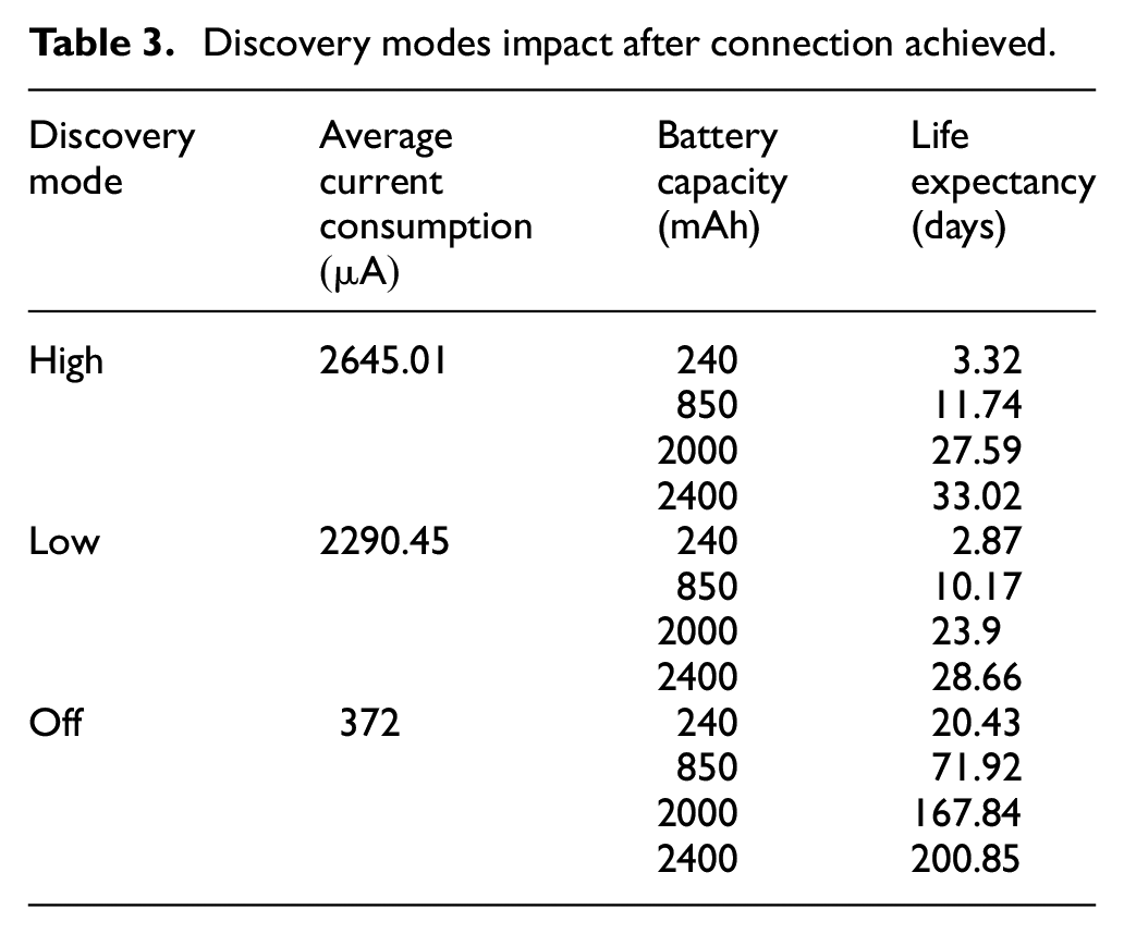
Once the connection is established, we measured the impact on the energy consumption of the three modes. Because this is the state the node will remain for most of the time, we based our battery life expectancy on these findings, using equation (2). With a 2000 mAh battery, we get an expected maximum lifespan of 5 and a half months. Meanwhile for the relay nodes, with 2400 mAh AA batteries, the lifespan reaches up to a little more than 6 and a half months. A comparison between the discovery modes’ power consumption and battery life expectancy is shown in Table 3.
Discovery modes impact after connection achieved.
System responsiveness
Figure 12 shows the relationship between system responsiveness and network density where we can observe that, for a specific hall door, the optimum number of relay nodes is 2, which represents a node density of a node every 6.5 m. Over this number, there are diminishing returns, as there is little improvement in responsiveness to justify the cost of adding more relay nodes to the network.

In our BMP application, the optimal node density is placing a node every 6.54 m, represented here as 2 relays. As expected, deep-sleep adds on average a 1-s delay only to the request time. Each data point represents an average of 30 measurements with a 95% bootstrap confidence interval.
Figure 13 shows the relationship between the client node polling period in seconds and system responsiveness. The client node continuously polls the server node for a change in the NOTIFICATION state to provide feedback to the visitor. Therefore, as expected, the polling period does not affect the request time and has a strong effect on the reply time. After a polling period of 1.5 s, the reply time increases rapidly.
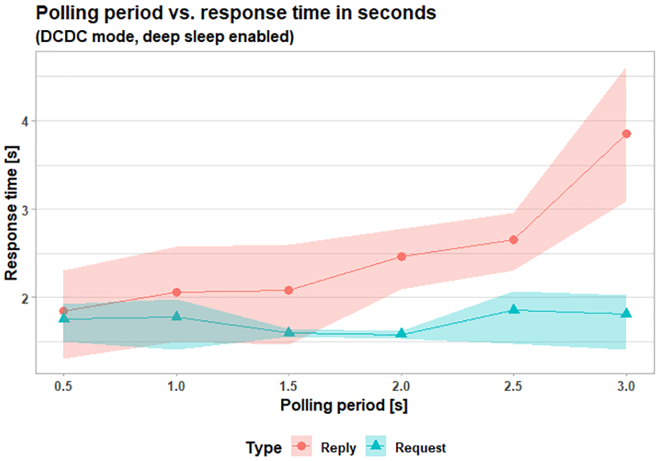
Reply time increases rapidly after a polling period of 1.5 s. As expected, request time is not affected. Each data point represents an average of 30 measurements with a 95% bootstrap confidence interval.
In FruityMesh, when the client node is awaken from deep-sleep mode, it has to be enrolled again to be part of the network before it can publish a message. This enrollment process takes approximately 10 s, causing long delays when measuring request time in the FruityMesh version of the Smart Doorbell. This effect can be seen in Figure 14 where a direct system responsiveness comparison is shown between BMP and FruityMesh. For a fair comparison, we used a maximum of 3 relay nodes in both deployed networks.

System responsiveness comparison between BMP and FruityMesh using number of relays as a proxy measurement for node density. Each data point represents an average of 30 measurements with a 95% bootstrap confidence interval.
For the request and response time we evaluated the impact of the number of relay nodes in the FruityMesh network. Overall, we see a reduction in the average request time but no important impact on the response time while increasing the node density. The relay nodes were placed at similar distances between each other and the server and client nodes. No data was obtained with no relay nodes, as server and client nodes were too far apart to send messages to each other. The results can be appreciated in Table 4.
Mean request and response time by number of relays.

Discussion
The results obtained point to a mesh network where nodes need to be placed on average every 7 m, need to use the DCDC power regulator with 4 dBm gain on every node, and use deep-sleep mode only on client nodes for BMP. Using this configuration, we can expect system responsiveness of around 2 s and a battery life of more than 1 year on our client nodes (the doorbells). Responsiveness of 2 s is acceptable for our application; however, the need to place grid powered relay nodes every 7 m is a major limitation.
In BMP, the need for the client node to poll the state of the server incurred a performance penalty of several seconds when comparing reply responsiveness with FruityMesh. However, request responsiveness in FruityMesh is severely affected due to network enrollment times of around 5 s in High discovery mode and 17 s in Low.
Bluetooth Mesh was not designed to support deep-sleep mode in relay nodes and despite our efforts to simplify the firmware, increase the polling period, and optimize power consumption using the DCDC regulator we obtained a maximum battery life of 2 weeks for relay nodes. Using larger batteries to increase the lifetime of relay nodes was impractical because the nodes will become too bulky and expensive. With FruityMesh, we see battery lifetime further extended by deactivating the DISCOVERY state, gaining autonomy, but at the same time leaving the client node without the possibility of entering into deep-sleep mode. With this state off, the relay and client nodes will be using an average of 372 µA, rendering a lifetime of 6 and a half months using a 2400 mAh Li-ion battery.
Because the mesh nodes will return to High discovery as soon as one of them disconnects from the network, this downtime must be the least possible, to minimize the time the nodes stay in that mode. Alternatively, the Low mode could be used instead. The trade-off is a fast connection versus reduced energy consumption.
Our system was designed with a known quantity of nodes for the mesh network, and therefore, it was easy to determine when to switch off the discovery state. The drawback is that if we change that quantity for whatever reason, we will have to re-program each of the nodes. Therefore, this method is not scalable for FruityMesh. Bluerange, FruityMesh’s commercial implementation, provides a Device Firmware Upgrade (DFU) 19 to update the mesh nodes from the cloud.
We obtained our results using a low quantity of nodes, with a small BMP network. Our graphs show reductions in time while increasing the number of relay nodes in the network, but it has to be stated as a caveat that such behavior is not expected to continue indefinitely. With a greater amount of relay nodes, we will experience noticeable performance issues due to message collisions.
It is important to notice that higher battery life expectancy can be obtained with higher capacity batteries, as stated by Hernández-Solana et al., 11 with a 10,000 mAh battery it would last about 83 days. However, it will have an impact on the overall implementation and deployment costs.
Conclusion
Our implementation of the Smart Doorbell gave us some further insights into the capabilities and limitations of a Bluetooth Mesh network. The fact that Bluetooth Mesh uses flooding to transport messages across the mesh network constraints relay nodes to be grid powered. In our case, despite our best efforts to reduce power consumption and network density, our network deployment required placing a grid-powered node every 7 m to maintain an acceptable system responsiveness time of 2 s. This limitation is a deal-breaker for several building automation applications, including the Smart Doorbell.
Overall, we can corroborate the conclusions of Darroudi et al. by obtaining a practical battery life of around 2 weeks for our relay nodes. In addition, the client–server model of our solution forces a client node to poll for state changes in the corresponding server node. Therefore, the use of polling penalizes application responsiveness when comparing it with FruityMesh. Also, we can expect increased network traffic and perhaps congestion as the application scales due to the use of the polling mechanism.
On a more positive side for BMP, network nodes do not need an additional wireless technology for provisioning, as mobile devices can natively connect to a node’s BLE stack. This was the strongest advantage of using BMP because it reduces cost and enables seamless provisioning.
Future work
The responsiveness characterization of our BMP and Fruitymesh networks could be further improved by adding more scenarios, for example: the failed request use case and congestion caused by several simultaneous requests.
FruityMesh offers a longer battery life than BMP for the network backbone. Our implementation of the Smart Doorbell with FruityMesh allowed us to have battery-powered relay nodes after removing, what we consider are the main power-consuming features, from the default implementation of the FruityMesh protocol. Nevertheless, there are other factors in the FruityMesh algorithm that can be modified to achieve even lower power consumption, such as advertising frequency and scanning windows. The analysis of the impact of these changes on the request, response, and power consumption could be topics for further studies.
Footnotes
Handling Editor: Peio Lopez Iturri
Declaration of conflicting interests
The author(s) declared no potential conflicts of interest with respect to the research, authorship, and/or publication of this article.
Funding
The author(s) received no financial support for the research, authorship, and/or publication of this article.