
Abstract
The significant growth of machine-to-machine applications for low-power cellular Internet of Things has compelled 3rd Generation Partnership Project to ensure that the future release of long-term evolution can support massive transfer of small, infrequent packets using ultra-low-power and low-cost devices. The 3rd Generation Partnership Project version of machine-to-machine, called “machine-type communication,” is currently being standardized for low-cost machine-type communication operations. In this article, a complete synchronization and cell search procedure is described for machine-type communication devices in long-term evolution systems. Low-complexity algorithms for primary synchronization signal and secondary synchronization signal detection, which requires the highest computational complexity in synchronization and cell search period, are also proposed for low-power machine-type communication devices. Through simulation under long-term evolution-based machine-type communication environments, we show that the proposed methods for primary synchronization signal and secondary synchronization signal detection require six and five times less computational complexity than the conventional methods, respectively, while their performance is similar. The proposed algorithms allow machine-type communication devices in a discontinuous reception cycle to resynchronize quickly with less power when synchronization is lost during a deep sleep period.
Keywords
Introduction
The growing pervasiveness and ubiquity of small and cheap computing devices is paving the way for the realization of the Internet of Things (IoT) vision.1,2 Several billions of such devices that use machine-to-machine (M2M) communication are predicted to come into existence over the next few years, and the majority of them are expected to be wireless sensors.2–4 A large variety of communication technologies that connect such devices have emerged to support a large diversity of applications: Bluetooth in personal area networks, Zigbee in home automation systems, WiFi in local area networks, and cellular networks.5–7
The significant growth of M2M applications, such as smart metering, remote security sensing, energy management system, and healthcare monitoring, has compelled 3rd Generation Partnership Project (3GPP) and the cellular industry to ensure that the design and development of future long-term evolution (LTE) releases can support massive transfer of small, infrequent packets using very low-cost, low-complexity, and low-power devices.8–10 The 3GPP version of M2M, called “machine-type communication” (MTC), was standardized in release 12 (Rel-12). 11 In Rel-12, a new profile, referred to as “category 0” (CAT-0) was defined for low-cost MTC operation. This evolved to a future release (Rel-13) that is currently being developed and is expected to be released in 2016.4,12 The main objectives are to enhance the monitoring of service quality and support ultra-low-power, low-cost, and narrow-band user equipment (UE).13,14 Eight of the world’s leading standards bodies, including the European Telecommunications Standards Institute (ETSI) and Association of Radio Industries and Businesses (ARIB), have come together to create one M2M.15,16
Low-power consumption is a key requirement for enabling long battery life for MTC devices.17,18 For example, some sensors/actuators installed inside the concrete could require a long time for battery replacement. Years of battery life might be required because replacing the battery is not an easy task. The low-power design is also required for cost reduction of MTC devices. 14 Discontinuous reception (DRX) mechanisms that allow receivers to turn their radio chip off during a predefined period have also been introduced for power saving. 19 DRX parameters, such as cycle period, sleeping time, and wake-up time, are controlled by networks, that is, eNodeB in LTE systems. A long sleep duration (up to several minutes) is allowed for MTC device (CAT-0).20,21 However, the receiver might lose its synchronization while switching off its radio circuit. The MTC receiver needs to wake up earlier than the predefined time in order to perform synchronization before decoding any data in the control channels.14,22 Therefore, a low-complexity synchronization method is required for MTC devices to shorten the period, thereby increasing sleeping duration (battery life). Furthermore, the MTC devices are allowed to use only one receive antenna at the minimum bandwidth for power-saving purposes. 6 Therefore, receive diversity gain cannot be obtained in MTC devices because they have only one antenna. However, MTC receivers can still obtain transmit diversity and repetition gains with their single antenna. 23
In this article, we propose low-complexity synchronization methods that can reduce the power consumption of MTC devices during the synchronization period. The synchronization methods are developed based on two synchronization signals (primary synchronization signal (PSS) and secondary synchronization signal (SSS)) that have been used in legacy LTE systems.24,25 A new synchronization signal cannot be designed for MTC devices, because the synchronization signals need to be compatible with legacy LTE systems. In order to complete downlink cell search, MTC devices also need to decode both master information block (MIB) and system information block (SIB) as UEs in legacy LTE systems. If cell ID is wrongly detected, decoding broadcast information is useless. Therefore, accurate synchronization with low-complexity algorithms using PSS and SSS is important for MTC devices. In this article, we describe a complete synchronization and cell search procedure for MTC devices. Two synchronization methods that can significantly reduce the computational complexity of MTC devices are proposed for PSS and SSS detection. The performance of the proposed methods is compared with those of conventional methods by simulation in LTE-based MTC environments.
The rest of this article is organized as follows. Section “Preliminaries” summarizes important characteristics of synchronization signals and physical channels required for the development of a synchronization and cell search algorithm in MTC devices. In section “Low-complexity synchronization methods for MTC devices,” a complete synchronization and cell search procedure is described for MTC devices. Two low-complexity synchronization methods for PSS and SSS detection are also proposed for MTC devices. The simulation results are given in section “Simulation.” Finally, a conclusion is drawn in the last section.
Preliminaries
In this section, we summarize important characteristics of synchronization signals and physical channels because MTC devices need to perform synchronization and cell searching using the synchronization signals and physical channels used in LTE systems. In the LTE system, two synchronization signals (PSS and SSS) are transmitted at the minimum bandwidth of 1.4 MHz in order to assist in the acquisition of synchronization parameters, such as symbol timing, carrier frequency offset (CFO), cyclic prefix (CP) type, frame timing, and cell ID. In addition, broadcast information is transmitted on two physical channels in order to assist in the completion of cell search. An MIB that carries information on the system bandwidth, system frame number, and physical channel hybrid ARQ indicator channel (PHICH) configuration is transmitted on the physical broadcast channel (PBCH). Another SIB that carries information such as public land mobile network (PLMN) ID and selection criteria is transmitted on the physical downlink share channel (PDSCH). A total of 504 unique physical cell identities (IDs) constructed by combining the cell ID group and cell ID within the cell ID group are supported

Here,
PSS is generated in the frequency domain from 63-length Zadoff-Chu sequence (ZCS) with zero punctuation at the DC subcarrier component.24,26 ZCS has good properties for synchronization signals, such as constant amplitude after fast Fourier transform (FFT) operation, ideal cyclic autocorrelation, and small cross-correlation value for any two ZCS whose root indices are relative prime. Three PSS with the root indices of 25, 29, and 34 are chosen to carry the information of cell IDs within the cell ID group. Each PSS is mapped to the 62 subcarriers around the DC component, thus occupying a system bandwidth of 1.08 MHz and allowing the use of the 64-FFT operation at the receiver. PSS is transmitted at the last orthogonal frequency-division multiplexing (OFDM) symbol of the first slot of subframes 0 and 5 for the frequency-division duplexing (FDD) mode, and at the third OFDM symbol of subframes 1 and 6 for the time-division duplex (TDD) mode. PSS is defined as follows

where

In equation (3), k denotes the subcarrier index that runs from
SSS, used to carry the information of the cell ID group, is constructed based on a cyclic-shift operation of maximum length sequence known as M-sequence with a length of 31.24,26 The cyclic-shift version of even indices is scrambled by another M-sequence whose cyclic-shift index is a function of

where cyclic shifts,

The basic sequence

In equation (5), the generic M-sequences,

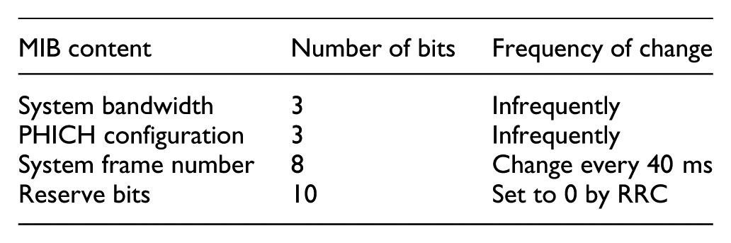
The MIB that consists of 24 bits is the most important broadcast information, which is transmitted on PBCH that occupies the resource grid of 72 subcarriers in the frequency domain and four OFDM symbols in the time domain. 23 MIB baseband processing is performed as follows: the 24 bits are attached with cyclic redundancy check (CRC) bits, encoded with tail biting convolutional coding, interleaved with rate matching, scrambled, mapped with quadrature phase shift keying (QPSK) modulation, precoded by a diversity precoder, mapped to the resource grid of subframe 0 for each antenna port.24,26 For a normal CP type, the number of bits increases from 24 to 1920 after interleaving, rate matching, and 16 repetitions.
Note that there are 10 bits to support all 1024 frame numbers. However, only eight bits are transmitted, whereas two bits are indirectly detected at the receiver. The received signal in the time domain is given by

where

where
Low-complexity synchronization methods for MTC devices
Because an MTC device must be compatible with legacy LTE systems, it needs to follow the cell search procedure used in the LTE system. Figure 1 shows a complete cell search procedure that will be used for the MTC device. The MTC device first needs to scan by measuring the received signal strength indicators (RSSIs) of all supported carriers for the entire bandwidth, each with 20 MHz. The measured RSSIs include the signal strength of the desired cell, interference cells, and noise. Then, RSSIs lower than the predefined threshold (or signal strength sensitivity) are filtered, resulting in a list of surviving candidates. Each surviving candidate is processed by the subsequent block until the MTC device finds a cell on which to camp. Synchronization and cell identification involve PSS and SSS detection. Using the received PSS, the MTC device acquires PSS location, cell ID within the cell ID group, and CFO. Using the received SSS, the MTC device acquires CP type, 10-ms frame boundary, and cell ID group. From MIB decoding, the MTC device acquires antenna configuration, system frame number, system bandwidth, PHICH configuration, and 40 ms frame timing. From the SIB decoding block, PLMN ID and selection criteria are decoded.

Complete synchronization and cell search procedure.
In this section, we describe the low-complexity synchronization algorithms that can reduce the power consumption of MTC devices during the synchronization period. The algorithms and decoding techniques that can be used for complete cell searching without changing the conventional ones are not discussed here. An MTC device detects the PSS location (symbol timing) by selecting the time index that corresponds to the maximum correlation output during 5 ms. By correlating the received signal with three local PSS, both the PSS location,

where

where

Note that two linear-shift cross correlators,
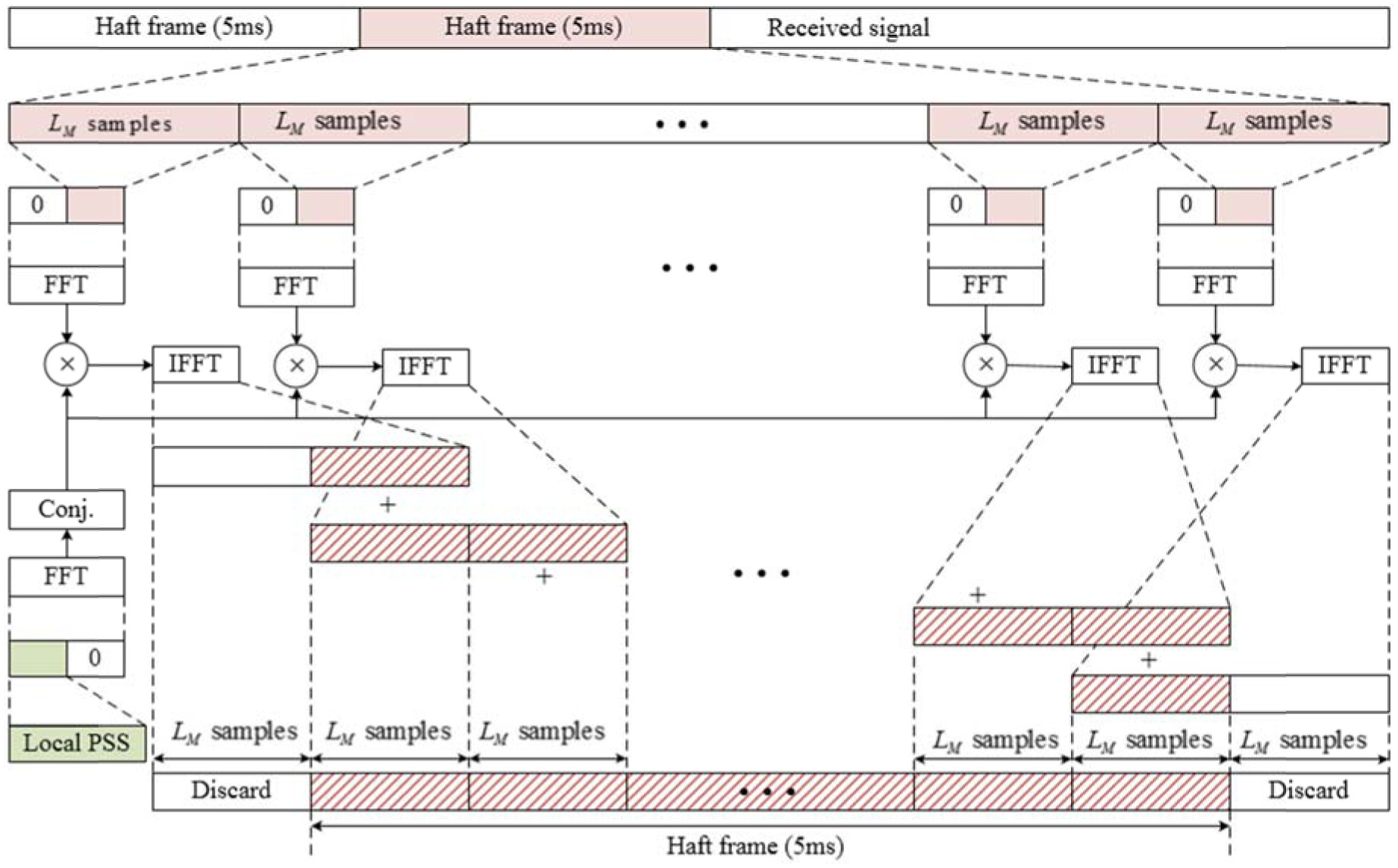
Method P2 for PSS detection.
Computational complexity for PSS detection.
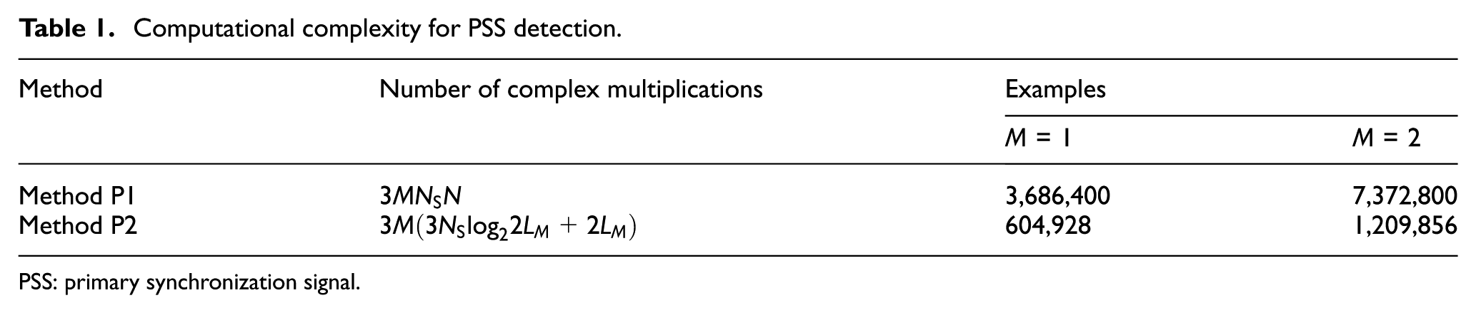
PSS: primary synchronization signal.
Here,
Figure 3 shows the SSS detection procedure. Here, the received time-domain SSS for each block is slid at a different window size and timing offset, depending on the type of hypothesis (normal and extended CP hypotheses). After finishing CP-type detection, CP is used for CFO estimation. The accuracy of CFO estimation can be improved by measuring the signal over a period of more than two OFDM symbols (CPs of both PSS and SSS) at the correct timing and CP length. If the CFO value is accurately estimated by the received PSS, the CP-based CFO estimation block is unnecessary. Then, SSS is compensated by the estimated value of CFO before it is transformed to the frequency domain. For a coherent detection case, the channel equalization block is mandatory. The block is not required for non-coherent detection cases. Next, the cell ID group number and subframe index (either 0 or 5) that carry SSS are estimated by correlating the received SSS with 168 local SSS in the frequency domain. This block requires the highest computational complexity, because SSS metrics need to be calculated by correlating the received SSS with all possible candidates. If the duplexing mode, either FFD or TDD, is not known to the MTC device, duplexing mode detection is required using the SSS metrics.

SSS detection procedure.
Here, we focus on the estimation method for the cell ID group and subframe index in order to reduce the computational complexity required to obtain the SSS metrics. Figure 4 shows the overall detection procedure for the cell ID group and subframe index. In Figure 4, the received SSS with 62 subcarriers is divided into two sequences, each with 31-length sequence on even and odd subcarrier indices. After descrambling, each sequence is processed by different correlators to estimate indices

Detection procedure for cell ID group and subframe number.
For hypothesis subframe 0,
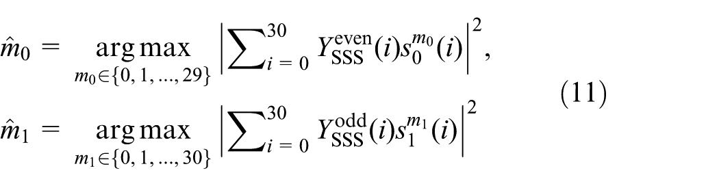
where

By comparing the SSS metrics obtained from the two subframe blocks, the synchronization parameters associated with SSS are finally determined. Note that 10-ms frame boundary can be indirectly obtained from the estimated subframe numbers. In this article, the conventional method for obtaining SSS metrics at the M-sequence level, equations (11) and (12), is referred to as “Method S1.”
Next, a method for SSS detection using the fast Hadamard transform (FHT) operation, referred to as “Method S2” in this article, is proposed. The FHT operation is used to reduce the computational complexity required to obtain SSS metrics. In order to use the FHT operation, the indices of each sequence need to be modified by a permutation operation. The permutation operation is not regarded as a multiplication operation, because it changes only the sequence indices. However, the permutation operation is expressed by matrix multiplication with a permutation matrix for notation convenience. The FHT operation that involves only an additive operation can be used to estimate indices

As shown in equation (13), the index that maximizes the correlation vector,
Low-complexity cell ID group estimator.

SSS: secondary synchronization signal.
Table 3 indicates the computational complexity required for SSS detection. In Table 3,
Computational complexity for SSS detection.

SSS: secondary synchronization signal; FFT: fast Fourier transform; CFO: carrier frequency offset; FHT: fast Hadamard transform.
After estimating the cell ID group, reference signal received powers (RSRPs) that correspond to candidate cell IDs are measured from reference signals. RSRP reflects the signal strength of each cell, which provides the selection of the serving cell. RSRP, obtained by a linear average of reference signal power in the available resource grid, is defined for cell c as follows

where

where

Here,
After selecting the candidate cell based on the RSRP measurement, the MTC device decodes MIB for the system bandwidth, PHICH configuration, and system frame number. In addition, the MTC device needs to acquire more information on the cell, such as antenna configuration and 40-ms frame boundary. Note that the MTC device cannot obtain receive diversity gain (only one receive antenna), but it can still obtain transmit diversity gain (many transmit antennas at eNodeB). Figure 5 shows the procedure of antenna configuration detection using CRC. As shown in Figure 5, eNodeB uses a two-antenna-port configuration for space-frequency block coding (SFBC) transmit diversity and a four-antenna-port configuration for combination of space-frequency block coding and frequency-switch transmit diversity (SFBC-FSTD). Therefore, there exist three hypotheses on antenna-port configurations: one, two, and four antenna ports. In order to detect the antenna configuration, the MTC device starts with one antenna-port configuration by estimating the channel using the reference signals at the minimum bandwidth. Subsequently, equalization, descrambling, demodulation and decoding, and CRC unmasking are performed. The local and unmasked CRCs are then compared for antenna configuration detection. Next, the MTC device detects 40-ms frame boundary by softly combining signals with 16 repetitive patterns and decoding MIB three times while shifting the window. With this scheme, we can obtain a combining gain with a processing delay of 70 ms. The 40-ms frame boundary can be also detected by descrambling the received MIB with four possible descrambling sequences. 24 In this scheme, we cannot obtain the combining gain. However, the processing delay for decoding MIB can be reduced to 10 ms.

Antenna configuration detection procedure using CRC.
The DRX mechanism in the LTE system allows a terminal device to conserve battery power and increase overall system capacity. A DRX cycle consists of an “On Duration,” during which the terminal device monitors the downlink channel, and a “DRX period,” during which a terminal device can omit reception of downlink channels for battery-saving purposes. 19 The terminal device achieves power saving by switching off most of its circuitries during the DRX period. DRX parameters, such as DRX inactivity timer, short DRX cycle, DRX short cycle timer, long DRX cycle, On Duration timer, DRX offset, and retransmission timer, are controlled by the networks. 20 In order to support the ultra-low-power consumption required by the MTC device, the duration of the DRX period is extended up to several minutes, implying that it can go to deep sleep mode while turning off most of its radio chip to conserve battery life. 29 When the MTC device loses its synchronization during the DRX period, it does not need to go back to the initial point, because it can start synchronization and cell search with the carrier selected previously. Unlike mobile UE, the MTC device in a DRX cycle, usually installed in a fixed location, does not need the process of neighboring cell search. Therefore, the MTC device in a DRX cycle can save additional battery power by omitting these steps and applying the low-complexity synchronization methods developed in this article when it wakes up.
Simulation
In this section, we evaluate the performance of the proposed synchronization methods for MTC devices in the LTE environment using MATLAB.26,30 All simulation parameters are taken from the LTE specification.23,24,31 It is assumed that the MTC device supports low-data rate and low-mobility operation.14,29 The following parameters are used for the simulation: bandwidth of 1.4 MHz, sampling rate of 1.92 MHz, and FFT size of 128. The FDD frame structure with normal CP type is used. It is assumed that both MTC device and eNodeB employ one antenna, implying that no transmit diversity gain is obtained. Because MTC devices are usually installed in a fixed position, the performance is evaluated under near static multipath fading channel (Extended Pedestrian A (EPA): 0/5 Hz and Extended Vehicular A (EVA): 0/5 Hz). In this section, performance results are shown only for the proposed synchronization methods (PSS and SSS detections). Other results (symbol timing, CFO, CP type, framing timing, and antenna configuration detection) that can be obtained by the conventional synchronization and cell search method used in the LTE system are not discussed.
Figure 6 shows the probabilities of PSS and SSS detection in the AWGN, EPA, and EVA channel environments. In Figure 6(a) and (b), the probability of PSS detection is shown with M equal to one. In these figures, 0 Hz (5 Hz) implies that the channel is a static (near static) multipath fading channel. Performances are evaluated over 1000 realizations of AWGN and multipath fading channels. In each realization, the channel power delay profile (PDP) is changed with different amplitude values of the multipath component, each experiencing Rayleigh fading. From Figure 6(a) and (b), one can see that the performances of Methods P1 and P2 are similar in all channels. The PSS detection probabilities of both methods in the AWGN channel reach 1 at a signal-to-noise ratio (SNR) of −5 dB, whereas those in the multipath fading channels reach 1 at an SNR of 10 dB. For example, 950 (0.95×1000) MTC devices out of 1000 can correctly detect the root index of PSS at the SNR of 2 dB. Figure 6(c) and (d) show the probability of SSS detection when the parameters associated with PSS (cell ID within cell ID group and PSS location) are estimated correctly.

Detection probabilities of PSS and SSS: (a) PSS detection with Method P1, (b) PSS detection with Method P2, (c) SSS detection with Method S1, and (d) SSS detection with Method S1.
From these figures, one can see that the performances of Methods S1 and S2 are similar in all channels. The performances of both methods are degraded slightly in all channels because both methods are based on coherent detection, and the channel estimates obtained from PSS are not accurate. In multipath fading channels, 910 (0.91×1000) MTC devices can detect the cell ID group correctly at an SNR of 2 dB.
Figure 7 shows bit error rate (BER) and block error rate (BLER) for MIB decoding in the AWGN channel. BLER is defined as the ratio of the number of block errors to the number of total realizations (1000). Block error detection is based on the CRC error detection mechanism. The number of bits used in BER calculation is the number of bits per block multiplied by the realization number (40×1000). For MIB decoding, the Viterbi decoding algorithm with soft-combining log-likelihood ratio (LLR) is used. As can be seen from the figure, performance improves as the number of repetitions increases. No error occurs when SNR is higher than 0 dB.
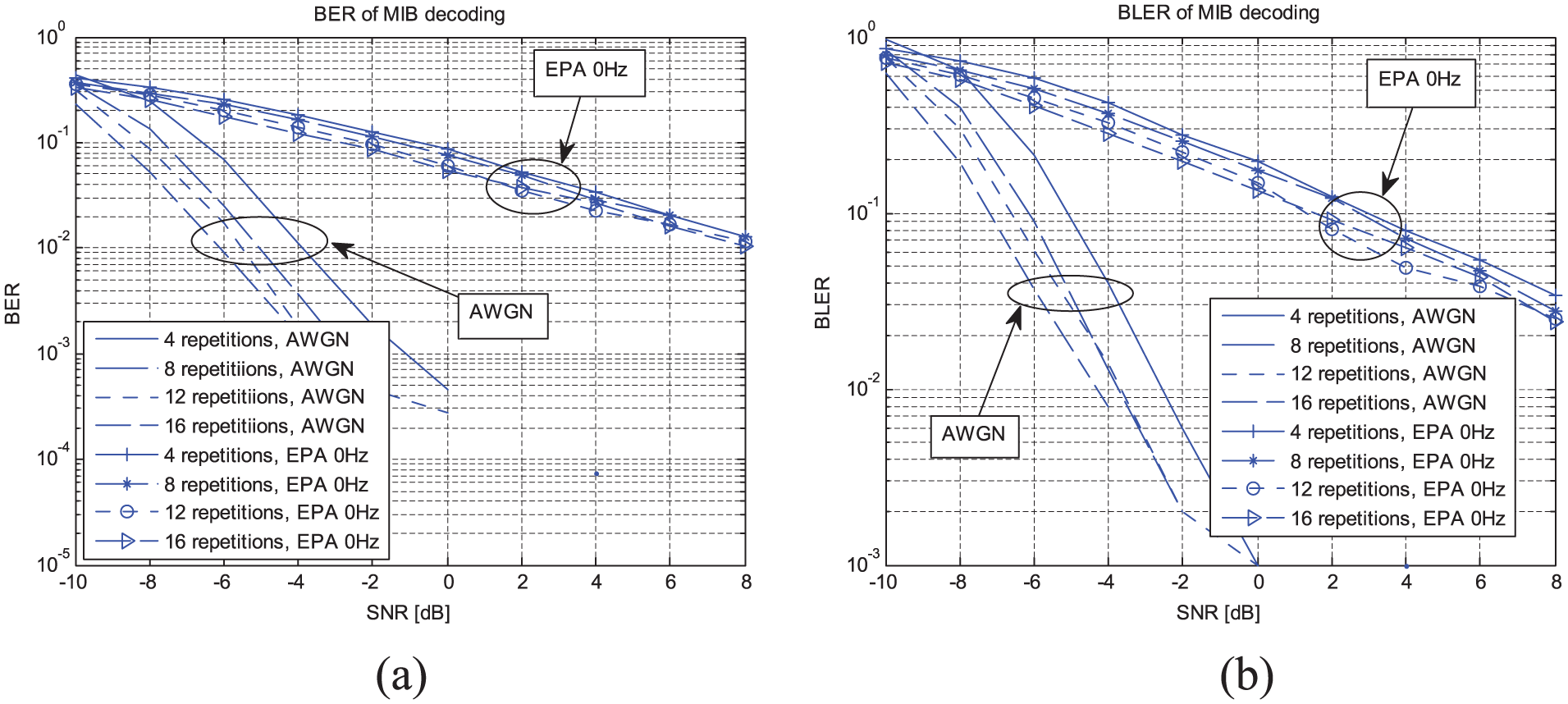
Performances for MIB decoding: (a) BER and (b) BLER.
Figure 8 shows the computational complexities required for PSS and SSS detection when the number of subcarriers varies. Figure 8(a) shows the number of complex multiplications required for PSS detection in the 5-ms period. From this figure, one can see that there are fewer complex multiplications for Method P2 than for Method P1, and the gap increases as the number of subcarriers increases. Figure 8(b) and (c) shows the number of complex multiplications and additions required for SSS detection, respectively. From these figures, one can also see that there are fewer complex multiplications for Method S2 than for Method S1. From these figures, one can see that Method P2 and Method S2 are appropriate for the synchronization of low-power MTC devices.

Computational complexity for PSS and SSS detections: (a) multiplication operation for PSS detection, (b) multiplication operation for SSS detection, and (c) addition operation for SSS detection.
The power consumption varies depending on the design architecture of the digital circuit cell, including adders, multipliers, and accumulators.32–35 To compare the performance in terms of power consumption, a multiplier based on the latch adder (LA), proposed in Chong et al., 35 is used in this article. The multiplier based on the LA was developed specifically for low-voltage power-critical low-speed applications in which the clock speed is lower than 5 MHz. Here, it is assumed that the signal amplitude is quantized at the 16-bit level, resulting in 16-bit arithmetic operation. All of the designs are based on the 0.35-µm complementary metal-oxide semiconductor (CMOS) fabrication process. For low-voltage (1.1 V) and low-speed (<5 MHz) applications, the power dissipation of one multiplication in Chong et al. 35 is 18.8 µW/MHz for a 16 × 16-bit multiplier. Additionally, the power dissipation of one LA is 10.1 × 10⁻⁸ W/MHz for one-bit operation. Therefore, the power dissipation for 16-bit operation is 1.616 µW/MHz (16 × 10.1 × 10−8 W/MHz). Figure 9 shows the power consumption required for PSS and SSS detections for different numbers of carriers. Here, the unit of power consumption is dBW/MHz (decibel Watt per MHz). The parameters in Tables 1 and 3 are used for calculation of the power consumption required for PSS and SSS detections, respectively. It is also assumed that one complex multiplication requires four real multiplications along with two real additions. Figure 9(a) shows the power consumption required for PSS detection when Methods P1 and P2 are used. It can be seen from this figure that the proposed method for PSS detection requires 8 dB less power consumption than the conventional method, regardless of the number of carriers and the value of M. Figure 9(b) shows the power consumption required for SSS detection when Methods S1 and S2 are used. This figure shows that the proposed method for SSS detection requires 7 dB less power consumption than the conventional method, regardless of the number of carriers.

Power consumption required for (a) PSS and (b) SSS detections.
Conclusion
In this article, a complete synchronization and cell search procedure was described for MTC devices in LTE systems. Low-complexity algorithms for PSS and SSS detection were also proposed for low-power MTC devices. It was shown by simulation under LTE-based MTC environments that the proposed method for PSS detection (Method P2) requires six times fewer complex multiplications than the conventional method (Method P1), whereas the performances of Methods P1 and P2 are similar. It was also shown that the proposed method for SSS detection (Method S2) requires five times fewer multiplications than the conventional method (Method S1), whereas the performances of Methods S1 and S2 are similar. The proposed algorithms allow MTC devices in a DRX cycle to resynchronize quickly with less power when synchronization is lost during a deep sleep period.
Footnotes
Academic Editor: Daniel Chen
Declaration of conflicting interests
The author(s) declared no potential conflicts of interest with respect to the research, authorship, and/or publication of this article.
Funding
This research was supported by the MSIP (Ministry of Science, ICT and Future Planning), Korea, under the ITRC (Information Technology Research Center) support program (IITP-2016-H8501-16-1007) supervised by the IITP (Institute for Information & communications Technology Promotion), and Basic Science Research Program through the National Research Foundation of Korea (NRF) funded by the Ministry of Education (2015R1D1A1A01057628).