
Abstract
Aimed at the demands of wireless sensor networks for high energy-efficient time synchronization, the reduction of synchronization energy consumption is studied from the aspects of both accurate timestamps marking and synchronous information transmission mechanism. First, the network is divided into several parent–child groups periodically. The group-wise pair selection algorithm is used to select the network’s pairwise synchronization nodes, and chain-type network topology is thus generated. Second, the sequential multi-hop synchronization algorithm is introduced to realize the synchronization information exchange among pairwise synchronization nodes. The overhearing synchronization (OS) nodes obtain the synchronization information packet based on a one-way overhearing mechanism. Moreover, the accurate acquisition of the synchronization ack packet’s timestamp is carried out through the use of receiving-time-plus-fixed-delay mode. Third, the joint maximum likelihood method and the minimum variance unbiased estimation method are used to estimate the clock offsets of pairwise synchronization nodes and overhearing nodes to the parent nodes, respectively, based on which the child nodes adjust their local virtual clocks. Periodically, the pairwise synchronization nodes initiate the network’s time synchronization, estimate, and broadcast the relative offset to the gateway node, assisting the upper layer child nodes in synchronizing to the gateway node. Simulation results show that the proposed method not only achieves the millisecond level synchronization accuracy but also reduces the synchronization energy consumption and thus improves the network lifetime.
Keywords
Introduction
Wireless sensor networks (WSNs) are composed of many self-organizing sensor nodes, which realize the interconnection between the physical world and the information world. It has been widely studied and applied in intelligent transportation, 1 intelligent manufacturing, 2 energy Internet of things,3,4 and other fields. Many important applications in WSNs—such as data fusion, transmission scheduling based on time-division multiple access (TDMA), and energy management—require different sensor nodes to work under a unified time baseline. Time synchronization is a fundamental support technology for WSNs.5–9 Due to the battery-powered characteristics of WSNs, energy efficiency is a virtual factor to be considered when designing corresponding time synchronization protocols. 10
In WSNs, the energy consumed by sensor nodes for communication (sending, receiving, and so on) is much larger than that consumed for computing, 11 and the information exchange mode can significantly influence the energy consumed for time synchronization. Based on the information exchange mechanisms of time synchronization protocols, the existing hierarchical time synchronization schemes can be classified into the following three types: sender–receiver synchronization (SRS), receiver-only synchronization (ROS), and receiver–receiver synchronization (RRS). SRS relies on the traditional model of two-way message exchange between a pair of nodes. For example, both network time protocol (NTP) 12 and time-sync protocol for sensor networks (TPSN) 13 rely on a series of heap synchronization that assumes two-way deterministic message exchanges. ROS is designed to minimize the number of timed messages and energy consumption required during synchronization while maintaining a high level of accuracy. 14 RRS is a method of synchronizing a set of child nodes that receive beacon information from a common transmitting node. Reference broadcast synchronization (RBS) 15 relies mainly on RRS because it requires message exchange pairs between child nodes to compensate for their relative clock offset. Pairwise broadcast synchronization (PBS) protocol is based on SRS of two-way synchronization message exchange between node pairs. 16 Inactive nodes located in the common communication domain of pair nodes can realize the clock synchronization with reference nodes by monitoring the two-way synchronization information exchange between pair nodes, which greatly reduces the node energy consumption. Therefore, PBS protocol is more suitable for WSN’s time synchronization with a limited power supply.
Moreover, it was pointed out in Freris et al. 17 that the transmission delay of synchronous information is a fundamental challenge to time synchronization, which directly makes it impossible for clocks between nodes to be synchronized. The time synchronization between nodes in WSNs essentially estimates the transmission delay. By recording multiple timestamps at both the sender and the receiver, the flooding time synchronization protocol (FTSP) method can effectively reduce the timestamp jitter of interrupt handling time and encoding/decoding time. 18 Timestamp-free synchronization method is a new mechanism that has attracted much attention in recent years.19–24 It was pointed out in Etzlinger et al. 20 that timestamp-free clock synchronization in a master–slave network, that is, synchronization where no timestamps were exchanged between the nodes, was considered. For the timestamp-free method, the synchronization process neither builds a special synchronous message nor requires any timestamp information interaction. In Etzlinger et al., 21 one following response mode was proposed to realize the timestamp-free synchronization protocols. The relative clock skew was estimated by sending back one ack packet and one following ack packet at two preset intervals. Wang et al. 22 proposed one dynamic response mode, and the dynamic response packet time interval was used to eliminate the dependence on the following packet. Combined with signal processing technologies, such as maximum likelihood estimation and linear unbiased estimation, the relative clock skew and clock offset were further estimated through multiple packet interactions between nodes.21,22 In Wang et al., 23 one hybrid synchronization scheme that uses one-way message dissemination and emerging timestamp-free synchronization was developed for WSNs without additional communication overhead. Under the Gaussian delay model, the maximum likelihood estimator for the joint estimation of clock offset, skew, and the fixed delay was derived, as well as corresponding Cramer–Rao lower bounds. Huan et al. 24 proposed an asymmetric timestamp-free time synchronization scheme with two estimation methods tailored for resource-constrained WSNs. Since no timestamp information is exchanged among nodes, the timestamp-free synchronization mechanism reduces communication energy and bandwidth consumption. It also avoids potential malicious attacks on the timestamp information, improving the security of the time synchronization mechanism.
Considering the limited energy supply in WSNs, in this article, we extend the timestamp free for node level to the network level and propose one energy-efficient network-level time synchronization algorithm. First, the synchronization energy consumption reduction is studied using the timestamp marking method and the synchronization information exchange mechanism. Then, a new sequential multi-hop synchronization algorithm (SMA) based on the new timestamp mark method is proposed. The main contributions of this article are listed as follows: (1) during the two-way time information exchange between pairwise synchronization (PS) nodes, the receiving-time-plus-fixed-delay mode is introduced, and a new ack packet timestamp processing mechanism is proposed; in this way, the packaging process of the current sending time’s timestamp is avoided, and thus the uncertainty of transmission delay is reduced and (2) a global network time synchronization mechanism based on SMA and PBS is proposed; thus, the information exchange between OS nodes and parent nodes is avoided, while the amount of information exchange among PS nodes gets decreased, and the energy efficiency of the time synchronization method is thus improved.
The rest of this article is organized as follows. The WSN clock model and the network topology generation method are presented in section “Time synchronization scheme.” Section “Time synchronization between parent and child nodes” discusses the information transmission model between parent–child nodes, clock offset estimation, and clock information adjustment. Section “Network multi-hop time synchronization” describes the network time synchronization method. Finally, section “Simulation results and analysis” provides the numerical simulation results and analysis of the proposed time synchronization method, and section “Conclusion” concludes this study.
Time synchronization scheme
Clock model of nodes
The first-order time model for a node

where
Note that

Definition 1 (Network time synchronization)
For a WSN network G with
Generation of chain-type network topology
Based on the communication between nodes in the network at the perception layer and the principle of the fewest parent–child groups, the whole network is divided into several parent–child groups starting from the gateway node, and appropriate PS nodes are selected for each parent–child group. Two-way time synchronization packets are exchanged between parent nodes (including the sink node) and PS nodes. Other nodes in the group overhear the time synchronization packets (recorded as OS nodes) to realize the time synchronization to their parent nodes.
The generation of chain-type network topology includes two steps: network spanning tree generation stage and group-wise pair selection algorithm (GPA)-based PS vector generation stage. Figure 1 shows an example of the GPA-based chain-type network topology. In Figure 1, there are four layers and five parent–child groups with layer number

Example of chain-type network topology.
During the network spanning tree generation stage, the gateway node
Remark 1
During the time synchronization process, the apoptosis or weakening of nodes will affect the network’s communication topology. In some cases, the topology may be a disconnected one. Therefore, the network topology should be regenerated periodically to avoid the influence of apoptosis or the weakening of nodes on the time synchronization performance.
Time synchronization between parent and child nodes
In this section, we mainly introduce how to implement a network’s time synchronization method in a new timestamp-marked way, including the SMA-based time synchronization model, the timestamp processing method, the relative clock, and skew offset estimation, together with the adjustment of the node’s virtual clock.
Time synchronization information transfer model
To reduce the total amount of synchronization information transmitted in the WSNs, and improve the energy effectiveness of the time synchronization method, one continuous multi-hop time synchronization model and the overhearing-based synchronous message transmission mode are adopted in this article. The fundamental idea of SMA is that the upper and lower nodes can simultaneously receive the time information sent by the current node. While the overhearing node makes use of the overhearing mechanism of wireless communication. When the synchronization information is exchanged between two nodes, the information can be overheard by the nodes within their common communication range.
Information transmission model and timestamp process
Figure 2 illustrates the SMA-based information transmission strategy for a network with

Information transmission model for time synchronization.

Overhearing-based synchronization packet exchange process.
In the SMA transmission, as shown in Figure 2, the PS child nodes at the third layer send a syn packet containing synchronization request to the parent nodes at the second layer, and the OS nodes in the third layer within the same parent group overhear those syn packets. After receiving the syn packets, the parent nodes at the second layer return an ack packet to the OS nodes in the third layer, which will be overheard by the OS nodes in the same parent–child group. As the PS nodes at the first layer also accept the ack from the second layer, it will also return an ack packet to the second layer. Meanwhile, the nodes at the first layer take the ack from the second layer as its synchronization requests packet syn. Similarly, nodes at the layer
As shown in Figure 2, when a node at layer

It should be pointed out that although
Synchronous information transmission model
First, the two-way exchange information transmission process between the terminal PS node and its parent node is presented. Under the designed information timestamp method, the PS node periodically initiates the time synchronization process and the information exchange process between the terminal PS node (denoted as
The kth information change between the terminal PS node
As for the synchronization information exchange of other PS nodes in the network, set the maximum number of network layers as
All the OS nodes in the network acquire their synchronization information packets based on the overhearing mode. As shown in Figure 3, in the kth two-way information exchange between PS child node
Clock offset estimation for two-way information exchange nodes
Taking the PS child node

where

where

where
In this article, we assume that

Assume that the fixed delay

According to the likelihood function formula (6), the joint maximum likelihood estimation of
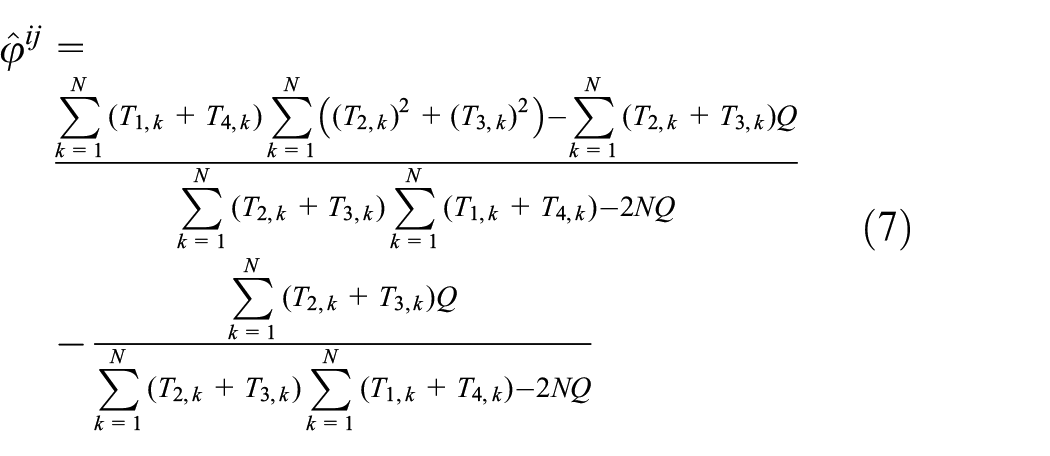
and

where
Clock offset estimation for one-way overhearing nodes
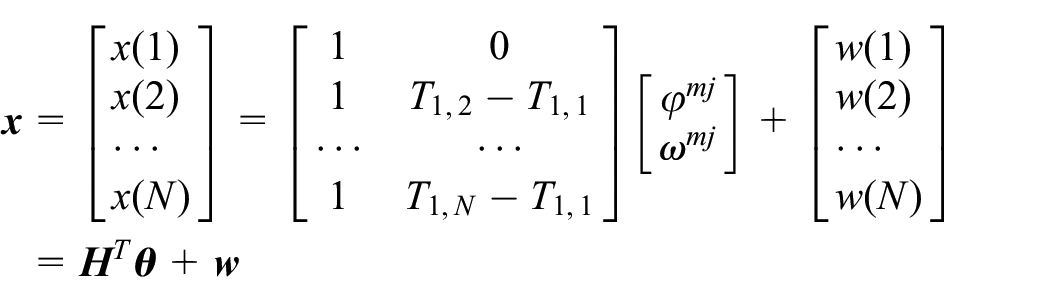
This section focuses on how the OS node in Figure 1 is synchronized to its parent node. Based on equation (3), the time relationship between the local time of the node

where


By combining equations (10) and (11), one can get

where the relative clock offset and clock skew satisfy
In this article, we assume that the values of
where

According to Theorem 3.2 in Kay Steven
26
if

and

where
Let

where
It should be pointed out that, in equations (13) and (14),
Network multi-hop time synchronization
Based on the time synchronization between the parent and child nodes, we will continue with how to achieve time synchronization at the network level in this section.
Network synchronization process
The time synchronization at the network level can be summarized in the following three steps:
Step 1. The PS node at the end of each link initiates synchronization periodically according to the synchronization period
Step 2. After, respectively,
Step 3. Time synchronization at the network level is carried out periodically. Starting from the first layer, the PS node sends the estimated relative clock offset and clock skew to the parent nodes at the previous layer, assisting the child nodes at the previous layer to be synchronized to the sink node. This process continues until all nodes at the
With some manipulations, the clock expression of the nodes at any layer

where

In this case, when nodes at layer
Network estimation stage
After finishing the time synchronization phase, the terminal node at each end of the chain network obtains the maximum clock and skew offset related to the sink node (reference time). Then, to meet the clock synchronization accuracy
Simulation results and analysis
The effectiveness of the proposed time synchronization method is verified on the MATLAB platform.
Simulation parameter setting
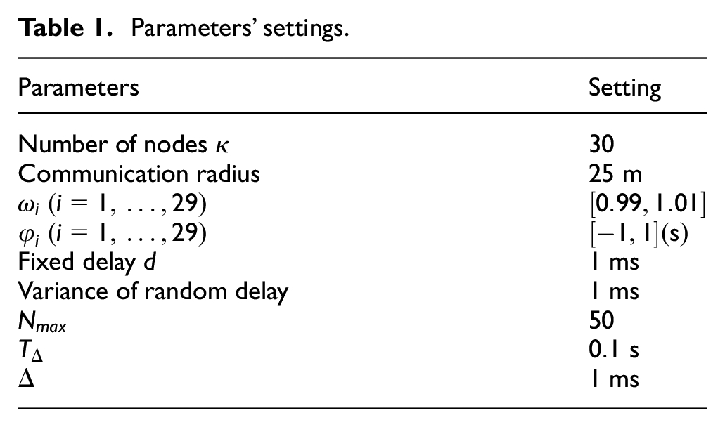
In simulating the network communication topology in a narrow space environment, 30 nodes (one of which is a sink node) are randomly arranged in a rectangular area, and the communication radius of the nodes is set to 25 m. If the distance between two nodes is less than 25 m, the two nodes are neighbor nodes. On the premise that the network contains at least one spanning tree, the initial topology of the generated network is shown in Figure 4(a), where the sink node is located at (0,3), and the big black solid point represents the sink node and the solid blue line represents the communication between nodes.

Network communication topology. (a) Initial topology and (b) GPA-selected topology.
The sink node provides the reference clock for the entire network with the clock skew set as 1, and the clock offset set as
Parameters’ settings.
PS node selection
GPA algorithm is run on the initial network topology shown in Figure 4(a) to select PS nodes, and the network topology constructed is shown in Figure 4(b). In Figure 4(b), solid red circles represent the parent nodes (including the sink node), solid green circles represent the PS nodes, and solid black ones represent the OS nodes. The red outer ring with a green filling represents the node that is not only the PS node in the previous group but also the parent node in the next group. The blue dotted thin lines represent the group’s communication between PS nodes and OS nodes; the red dotted lines represent the communication between parent nodes and OS nodes; while the blue dotted thick lines represent the communication between parent nodes and PS nodes in a group. By comparing Figure 4(a) and (b), it can be seen that the number of nodes that need bidirectional exchange in the network is only 3 through the selection of PS node pairs, which can significantly reduce the synchronization information transmitted in the network.
Synchronization error analysis
First, the synchronization error simulation analysis of single-hop nodes is carried out. After

respectively. For PS and OS nodes, Figure 5(a) shows the relationship between the clock offset estimation MSE and the synchronization information exchange time
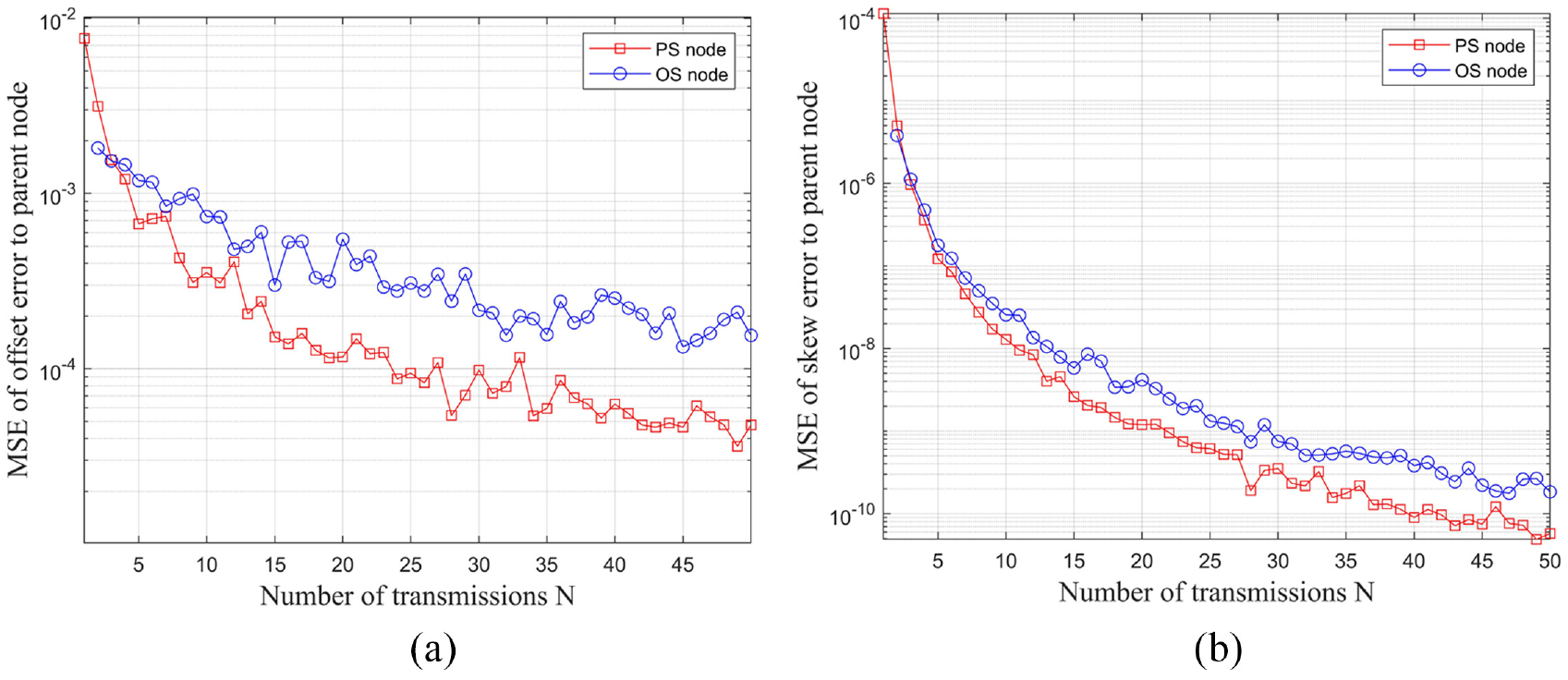
Relationship between one-hop clock estimation MSE and number of transmissions
We can see from Figure 5 that (1) as the number of transmissions
Next, the synchronization errors of nodes at different layers relative to the sink node are simulated. For a child node

By taking the maximum estimation errors of nodes at the same layer as the estimation error of that layer relative to the sink node, we can obtain the relationship curves between the clock skew estimation error and clock offset estimation error of nodes at different layers to the sink node concerning the number of transmissions

Skew error to sink node for nodes at different layers. (a) PS nodes and (b) OS nodes.

Offset error to sink node for nodes at different layers. (a) PS nodes and (b) OS nodes.
From Figures 6 and 7, one has:
The time synchronization method proposed in this article can realize time synchronization at the network level: when the number of synchronization information exchanges is set as
The clock skew and clock offset synchronization errors of nodes relative to the sink node increase with the increase in network hierarchy; therefore, the number of layers
For PS nodes, as the number of synchronization information exchanges increases, the synchronization errors of all hierarchical nodes relative to the sink node decrease significantly. Increasing
The estimation errors of OS nodes are larger than those of PS nodes, and the declining trend is gentle with the increase in
Analysis of synchronization energy consumption
Data transmission in time synchronization accounts for the majority of the energy consumption of the time synchronization algorithm.11,27 Thus, the energy consumption of the algorithm is measured by the synchronization data amount of the algorithm, that is, the total amount of packet needed in one time synchronization period. For the network topology shown in Figure 4, the number of nodes to be synchronized is 29, and
The comparison between the synchronization method in this article and the other three typical time synchronization algorithms is shown in Figure 8. From Figure 8, one can have that the method proposed in this article consumes the least synchronized data amount. That is because the GPA method is adopted in this article for network PS node selection and the SMA mechanism is introduced into the time synchronization at the network level.

Synchronization packet amount comparison among some time synchronization methods.
As seen in Figures 6–8, the introduction of an overhearing-based time synchronization mechanism can significantly reduce the synchronization information transmitted in the network and improve time synchronization accuracy. However, the effect of the overhearing mechanism on improving accuracy is worse than that of the bidirectional information exchange mechanism. In practical design, the compromise between synchronization accuracy and synchronization information amount can be achieved through a reasonable selection of PS nodes.
Conclusion
A continuous multi-hop time synchronization method based on a new-marked timestamp has been proposed in this article. First, one receiving-time-plus-fixed-delay mode has been introduced to realize the accurate acquisition of the synchronization ack packet’s timestamp. Then, the reduction of the synchronization data amount has been studied from three aspects: the GPA chain-type network topology generation, the continuous multi-hop time synchronization method, and the overhearing-based synchronization information acquisition. Also, the PS node nearest to the sink node periodically initiates the time synchronization at the network level. Other PS nodes in the network assist the upper layer child node in being synchronized to the sink node. Finally, some numerical simulations have been carried out to show the effectiveness of our proposed time synchronization method. How to design a time synchronization method robust to communication topology and delay in the constrained communication environment is the beacon of our future research.
Footnotes
Handling Editor: Yanjiao Chen
Declaration of conflicting interests
The author(s) declared no potential conflicts of interest with respect to the research, authorship, and/or publication of this article.
Funding
The author(s) received no financial support for the research, authorship, and/or publication of this article.