
Abstract
As the most important segment of the spindle unit angular contact ball bearing, the preload significantly influences the bearing characteristics. Thus, the thermal-induced preload derived from the thermal expansion of spindle unit components also affects the increase in bearing temperature, stiffness, fatigue life, and ball skidding significantly. However, such preload is hard to monitor and analyze. Thus, in this article, the authors presented a fiber Bragg gating sensor-based structure for the identification of thermal-induced bearing preload. In addition, a bearing total preload control mechanism was designed with an emphasis on its thermal component. Based on the comparison of the shaft and the outer ring deformation temperature increases measured by embedded fiber Bragg gating sensors, the reasonable bearing preload range was achieved based on Hirano’s theory. Finally, the conclusions provide a reference for improving the performance of angular contact ball bearings and reducing the spindle vibration.
Introduction
High-precision machine tool spindle units need to urgently meet the increasing manufacturing industry demands. Furthermore, as a core machine tool component, spindle unit dynamic characteristics are closely related to the bearing running status. Moreover, bearing performance and spindle thermal error are directly related to the angular contact ball bearing, which was widely used as it can withstand both axial and radial loads. The preload also has a significant role in the bearing running state.
The spindle thermal error is among the primary manufacturing error contributors when considering the machine tool working process. 1 Thus, applying the optimum preload can greatly improve both the bearing performance and the spindle thermal characteristics.2–4 For this reason, the study on the bearing preload selection is necessary.
Generally, the bearing preload is divided according to the implementation effect; there is rigid, constant, and variable bearing preload. In rigid preload conditions, due to thermal-induced and centrifugal force-induced loads, the bearing stiffness increases rapidly along with the bearing temperature. Furthermore, in constant preload conditions, the bearing has too low stiffness and practically invariable preload; therefore, the constant preload is only suitable for light-load cutting conditions. For this reason, the majority of recent studies were focused on the variable preload mechanism for providing a time-varying preload. Hwang et al.5–7 developed variable preload devices, including the electromagnetic actuator and electromagnets. Moreover, Razban and Movahhedy 8 and Kim and Le 9 proposed using rubber and eccentric masses to ensure that variable preload. However, such devices could only exert the variable preload on the bearing; whether the applied preload was optimal remained questionable.
Furthermore, the thermal expansions of the shaft, housing, and bearings will influence the bearing preload depending on the operating conditions. 10 This change part of the preload is the thermal-induced preload. The heat generation of bearings was modified by considering the thermal-induced preload of bearings. 11 And thermal-induced preload will lead to a further increase of the frictional heat generation and then cause the thermal failure of the spindle. 12
Thus, both the initial and thermal-induced preload should be studied to determine the optimum preload values, and the total bearing preload should be measured without affecting the spindle running process. Currently, the researchers have largely ignored both the thermal-induced and real-time bearing preload. In addition, the thermal-induced preload measurement and verification methods remained limited. Variable preload structures designed to date generally did not contain the thermal-induced preload. Even though the bearing preload is determined by multiple parameters, including the spindle speed, bearing outer ring temperature increase, spindle stiffness, balls skidding, and fatigue life, among others. First, it is not possible to build a realistic relationship between the spindle working status and bearing preload using only the spindle speed and stiffness13–15 since the stiffness is time-varying. Second, although it is useful to utilize the bearing temperature to determine the preload, current temperature measuring remains limited to the spindle surface. 16 Third, bearing fatigue life calculations remain theoretic without the use of extensive experiments. 17 The bearing preload range can be improved based on ball skidding.18,19 Finally, the optimal preload needed to minimize the spindle thermal deformation was not yet studied.
In addition, bearing stiffness accounts for 30% of spindle’s stiffness and is deeply affected by the thermal-induced preload. 20 Jafar Takabi and M.M. Khonsari predicted that higher viscosity and housing cooling rate will cause higher induced thermal preload and indicated the parameters such as rotation speed, lubricating oil viscosity, and thermal resistance had significant effects on thermal-induced preload. 21 Furthermore, due to the complexity and variability of spindle unit, the experimental test methods for online monitoring of bearing dynamic preload are strictly limited in practical applications. Only Yan et al. 22 studied the transient bearing preload using the state observer approach recently.
Aiming to study the bearing thermal-induced preload and the influence of total preload, the authors proposed the FBG (fiber Bragg gating) sensor-based structure and designed a bearing equipped with preload application structure. The obtained thermal-induced preload values were verified and the relationship between the total bearing preload and shaft thermal drift was mapped. Finally, the reasonable bearing preload range, including the thermal-induced portion, was achieved and tested using Hirano’s theory.
FBG sensor-based thermal-induced preload identification
Structural design
Compared to strain gauges and thermal resistors, FBG can simultaneously monitor temperature and force changes, and is more suitable for multi-parameter sensing of the spindle system, mostly due to its compact dimensions and strong resistance to electromagnetic interference. Hence, to improve bearing preload monitoring, the structure based on FBG sensors was designed. Furthermore, said structure contains four uniform beams and two support rings; two FBG sensors are mounted on each beam, as shown in Figure 1. The FBG 1 sensor is pasted along the beam axis (used to monitor the temperature and force changes after the initial preload is applied along the axis), while the FBG 2 sensor is pasted perpendicular to the axis (only used to measure the temperature change after the initial preload is applied). In addition, since the two sensors are very close, it can be considered that the temperature rise has the same effect on them.

The FBG-based structure.
When the temperature of the spindle system rises, the non-uniform temperature rise of the bearing components (which will generate thermal-induced preload) will be reflected in the structure described in Figure 1. The wavelength of FBG 1 changes under the combined action of temperature and thermal-induced preload. Due to the characteristics of the structure, FBG 2 can compensate for the temperature-induced wavelength change in FBG 1, so we can indirectly monitor the thermal-induced preload through the strain change of FBG 1.
The central wavelength change ΔλB of FBG1 can be described as follows

However, the central wavelength change ΔλB1 of FBG2 is
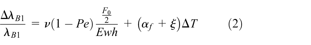
where λB and λB1 are the initial central wavelengths, αf is the thermal expansion coefficient, ξ is the thermo-optic coefficient, Pe is the strain-optic coefficient of the optical fiber, E is Young’s modulus of the structure, and h and w are the beam thickness and width, respectively.
Thermal-induced preload identification
Using the designed structure based on FBG sensors (gate length: 3 mm, reflectivity: 90%) and fiber grating demodulator (sensitivity: 1 pm) made by the Beijing TONGWEI sensing, bearing thermal-induced preload was measured at various spindle speeds and 350 N initial preload; the test system with four SKF 7010AC bearings is shown in Figure 2. The spindle system bearings were arranged in the “O” type configuration. The initial spindle unit temperature was 25°C.

The bearing thermal-induced preload test system.
A complete measuring process lasted 3 h and the specific results are shown in Figure 3.

The bearing preload test results (thermal-induced) at different spindle speeds.
Based on Figure 3, it is evident that the thermal-induced preload of bearing at various spindle speeds increased rapidly in the early stage. In the latter stages, the results stabilized. At high speeds, the thermal-induced preload reaches a larger value than low speed. This is caused by the high speed, which causes the spindle unit to generate more heat, ultimately resulting in a greater thermal expansion of the spindle unit components. Furthermore, the transient preload was much greater compared to the initial preload.
As shown in Figure 4, the thermal-induced bearing preload changes with time under different spindle speeds. Compared Figures 3 and 4, it can be found that the thermal-induced bearing preload increases with the bearing temperature rise, also verified that the thermal-induced preload is proportional to the temperature rise of the bearing.
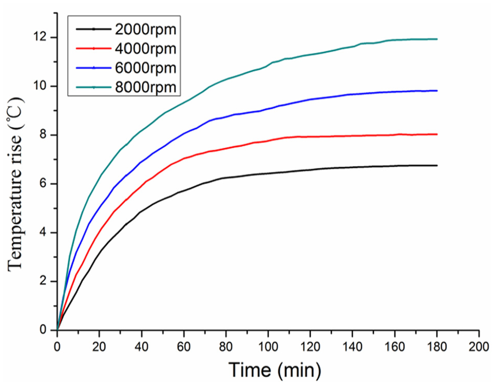
The bearing temperature rise at different spindle speeds.
Preloaded bearing status analysis
In this article, bearings were preloaded using axial force. The preloaded bearing analysis was carried out using a quasi-static method, 23 including the ball centrifugal force and gyroscopic bearing moment. A simplified schematic diagram of angular contact ball bearings is shown in Figure 5.
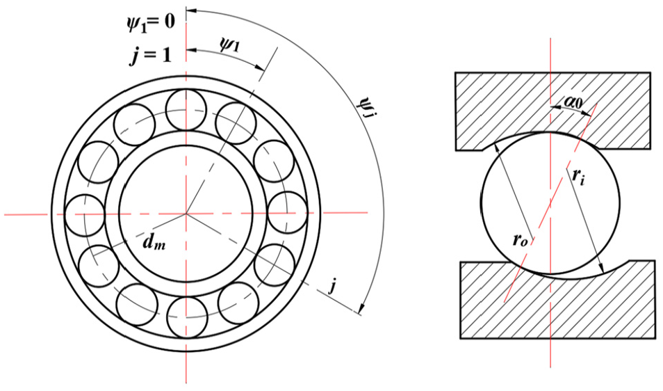
Simplified schematic diagram of angular contact ball bearings.
Using the rigid ring theory, it is assumed that the inner and outer rings of the bearing do not produce structural deformation under load, but only the rigid body displacement occurs. The deformation of the bearing is only related to the local deformation of the rolling elements and the ring. Under the action of a specific axial preload force Fa, the rolling elements are subjected to centrifugal force, and the contact angles of the inner and outer rings are different. Assuming that the center of curvature of the outer raceway B remains unchanged, the center of curvature of the inner raceway changes from A to

The relative position of the rolling element and the center of curvature of the groove.
At this time, the distance between the center of curvature of the inner and outer channels at the angular position ψj and the final position of the center of the rolling element are, respectively

where δij and δoj are the deformation of the contact between the rolling element and the inner and outer rings at the angular position ψj.
At the angular position ψj, the distances between the centers of curvature of the inner and outer channels relative to the axial and radial directions are

During the high-speed operation of the ball bearing, the actual contact angle between each rolling element and the inner and outer rings is not equal. The auxiliary variables X1j and X2j are introduced in Figure 6, and the actual contact angle between the inner and outer rings and each rolling element can be expressed as
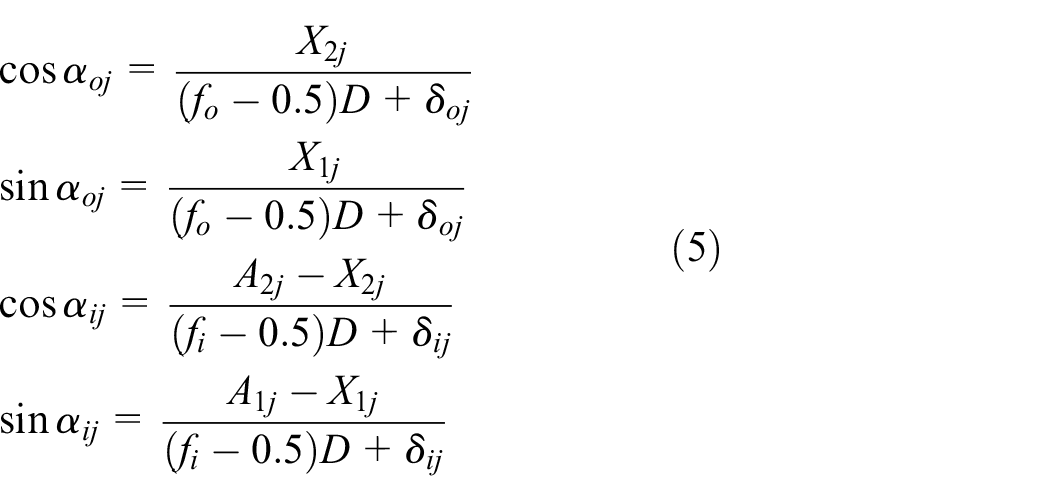
where αoj and αij are the actual contact angles between the rolling element and the inner and outer rings. In addition, from the Pythagorean theorem

At the angular position ψj, the force analysis of the rolling element is shown in Figure 7. According to Figure 7, the force balance equation of a single rolling body in the horizontal and vertical directions is
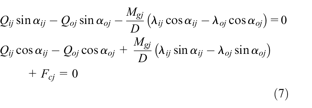
where


Force analysis diagram of rolling element.
For the entire bearing, the force balance equation in the horizontal and vertical directions is as follows

where Fa is the axial preload of the bearing. According to the external channel control theory, λoj = 2 and λij = 0.
Using the Newton–Raphson nonlinear equation solving algorithm, the dynamic contact angle, contact load, and axial displacement of the bearing under the action of different speeds and axial bearing preload force Fa can be obtained. The specific bearing 7012AC parameters are given in Table 1.
Specific bearing parameters.

Determination of the optimum bearing preload range
For a given axial preload, a maximum working speed is defined, reducing the Hertz contact area between the ball and inner ring to zero. According to Hirano’s theory, the centrifugal force of the ball and the contact loads between the ball and the inner raceway are critical for determining the bearing preload, as shown in equation (10) 24

where Qi is the contact load between the balls and the inner ring, αi is the contact angle between the balls and the inner ring, and p3 is the centrifugal force of the ball.
Moreover, using the preloaded bearing status analysis results, it was found that the ball load caused by the centrifugal action tends to be a constant value under different rotation speeds and preloads above 300 N. In addition, regardless of the bearing rotation speed, the value Qi*sinαi remains the same for various bearing preload values as shown in Figure 8, just as proposed in the previous work by Dong et al. 25

The 10*Ball centrifugal force and Q i *sinα under different preloads and speeds.
Hence, when the preload exceeds 300 N, ten ball centrifugal forces have no connection with the bearing preload. The Qi*sinαi is closely related to the bearing preload at a certain rotation speed. Moreover, based on Hirano’s theory, the minimum bearing preload needed to avoid ball skidding can be obtained using

where n is the bearing rotation speed (in r/min).
Experimental tests and discussion
Bearing constant preload control method
Since the thermal-induced preload accounts for a considerable share of the total preload, it has to be controlled. Thus, the experimental setup which can provide a constant bearing preload during the spindle running process was designed. This specific bearing preload mechanism provides a constant preload, enabling the authors to study its influences on other spindle running parameters, including the thermal preload. The proposed experimental setup of the spindle with four SKF 7012AC bearings is shown in Figure 9, which has the same bearings layout as the spindle unit in Figure 2.

The experimental setup.
The spindle system bearings were also arranged in the “O” type configuration and bearing locations were fixed using long spacers. The pipe chambers applied preload structure, and housing was filled with oil. As the fine tooth thread decreases the chamber size, oil forces the rear bearing outer rings to preload rear bearings, moving the rear bearing support along the shaft. Simultaneously, the inner front bearing rings move backward to preload the front bearings. Using such a bearing preload control mechanism, the same preload was applied to all the bearings. Its value is equal to half the pressure measured by the pressure sensor.
Moreover, when the thermal expansion of bearing supports and rings occurs, the fine tooth thread increases the space inside the chamber to ensure constant preload value. The fine tooth thread increases the space inside the chamber; therefore, the preload can contain the same preload avoiding the thermal-induced preload influences.
Results and discussion
Following the theoretical analysis, the shaft deformation was measured (as shown in Figure 10). Three KEYENCE LK-G80 laser displacement sensors were used to measure the shaft deformation in the three directions, with measurement accuracy of 0.001 mm. The thermal equilibrium was achieved during each test.

The shaft deformation measurement system.
All the tests were carried out at the spindle speed of 3000 r/min and approximately consistent ambient temperature conditions. Furthermore, since the spindle system structure was symmetric, and the thermal deformation was just thermal expansion of the shaft caused by a temperature rise of about 15°C, the Z-direction deformation of the spindle system was too small to measure. Thus, deformation measurement and analysis were focused on the X- and the Y-directions.
Based on the experimental tests, the final shaft deformation values were obtained and are shown in Figure 11. The optimal bearing preload was determined by avoiding the ball skidding; its value is 700 N for 7012AC angular contact ball bearing. Moreover, test results have shown that at 750 N preload, which was calculated using equation (2), the spindle system thermal error was the smallest.

The average final values at different bearing preloads.
Moreover, the shaft deformation for the spindle speed of 4000 r/min and various preloads and the bearing outer ring temperature increase at spindle speed 3000 r/min were tested. Testing has enabled the authors to compare the values with the shaft deformation curves. The FBG temperature sensors were arranged on the outer bearing ring and thermal grease was applied to the gap between the FBG sensors and the ring. The average value obtained by sensors was used to determine the final temperature results (see Figure 11).
As can be seen in Figure 12, the outer bearing ring temperature increase was minimal at the bearing preload of 750 N. Furthermore, Figure 13 shows that the reasonable spindle bearing preload is 1250 N, which is in agreement with the values obtained through equation (11).

The temperature increase curve of the bearing at a spindle speed of 3000 r/min.

The shaft deformation at a spindle speed of 4000r/min and various preloads.
The higher bearing speed, the greater optimum bearing preload. And the optimum bearing preload includes not only the initial preload, but also the thermal-induced preload which is closely related to the bearing temperature rise.
In addition, using the measured values of shaft thermal error and the bearing outer ring temperature increase, it is possible to obtain the optimum bearing preload. As shown above, the spindle thermal error trends follow the outer bearing ring temperature increases. Thus, the optimal bearing preload can be determined through the applied structure in the CNC machine tool testing phase without changing the spindle structure to measure the increase in bearing temperature.
Conclusion
In this article, the bearing thermal-induced preload was identified by FBG sensor-based structure and the mechanism for application of bearing preload was utilized. The mechanism maintained a specific preload value, which was considered to be the thermal-induced preload. Furthermore, the outer bearing ring temperature was measured using the embedded FBG sensors. The existing bearing preload selection method was improved and a specific equation for the bearing preload was obtained through Hirano’s theory. In addition, spindle system shaft deformations were measured and were directly related to the bearing preload. The outer ring temperature increase experiments verified the related results. Finally, the authors believe the proposed method will be useful for both the researchers and practitioners determining the optimal bearing preload values, as they also reduce the machine tool spindle vibration during the test stage.
Footnotes
Handling Editor: Francesc Pozo
Declaration of conflicting interests
The author(s) declared no potential conflicts of interest with respect to the research, authorship, and/or publication of this article.
Funding
The author(s) disclosed receipt of the following financial support for the research, authorship, and/or publication of this article: The authors acknowledge funding support from the National Key R&D Program of China (no. 2018YFB 2000504) and the Henan Provincial Department of Education Project (no. 19A460018), as well as the contributions from all collaborators within the projects mentioned.