
Abstract
We propose a new algorithm variant for Structure from Motion (SfM) to enable real-time image processing of scenes imaged by aerial drones. Our new SfM variant runs in real-time at 4 Hz equating to an 80× computation time speed-up compared to traditional SfM and is capable of a 90% size reduction of original video imagery, with an added benefit of presenting the original two-dimensional (2D) video data as a three-dimensional (3D) virtual model. This opens many potential applications for a real-time image processing that could make autonomous vision–based navigation possible by completely replacing the need for a traditional live video feed. The 3D reconstruction that is generated comes with the added benefit of being able to generate a spatially accurate representation of a live environment that is precise enough to generate global positioning system (GPS) coordinates from any given point on an imaged structure, even in a GPS-denied environment.
1. Introduction
Drones are ubiquitous in our modern world. From recreational hobbies to professional activities, they play an important role in our daily lives. However, to be used remotely or even autonomously, drones require ever increasing data rates to remotely transmit live imagery to operators. This is a costly endeavor for the development of drones and could put a lot of strain on future telecommunication systems if the amount of drones flying in the sky continues to increase at the rate currently projected.1,2 While one solution is the development of better communication infrastructure, we propose an alternative to live streaming imagery to remote operators. Our approach uses a computer vision algorithm variant to transmit similar data for a dramatic decrease in package size.
1.1. Application of real-time structure from motion
Building from recent research on this same topic using Structure from Motion (SfM), 3 which demonstrated 49%–60% compression from the original imagery, we propose a new SfM variant that is both faster and more spatially accurate than traditional methods, and most importantly, capable of calculating imagery replacements in real-time at 4 Hz on our test laptop.
SfM is a set of computer vision algorithms commonly used to create static three-dimensional (3D) models, known as a reconstruction, from a scene using only an unordered array of detailed two-dimensional (2D) photographs. From these photographs, relative camera locations of each image are recovered, and through the use of epipolar geometry, depth information is extracted from the comparison of different perspectives. An example of the input and output of this process is illustrated by Figure 1.
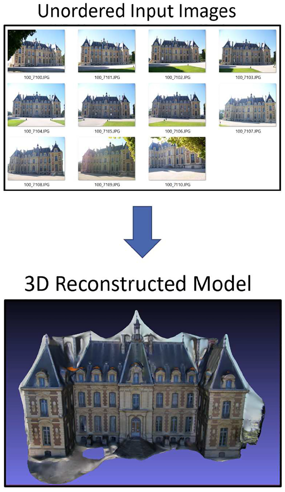
SfM example: input unordered images, output reconstruction.
Using a new computer vision technique combining SfM and planar homography transforms, we propose an algorithm capable of transforming urban environments into living 3D virtual models that can be transmitted in lieu of real-time video for a fraction of the bandwidth. Our preliminary research, shows that we are able to create simplified 3D models of sensed buildings that consume only one-tenth the size of the original video.
This research employed the AftrBurner 3D Visualization Engine created by Nykl et al. 4 It is an open graphics library (OpenGL)-based 5 rendering engine with an open computer vision (OpenCV) 6 integration. This OpenGL/OpenCV combination enables rapid and realistic virtual image generation as well as state-of-the-art computer vision processing. The strategic use of this visualization engine was vital to the development of the proposed method. A virtual environment enables repeatable analysis of information in a deterministic manner that conveniently eliminates many sources of error since the parameters of each experiment are explicitly specified and could be easily modified as needed. The virtual world also enabled a cost-effective testing environment, as no physical hardware other than a laptop was needed to conduct each experiment. In addition, the experimental environment for each test was not subject to real-world problems like weather and logistics related to real world flight, as well as the regulatory process that would be necessary to accomplish these tasks.
Finally, we encourage our readers to view our Youtube video on this algorithm at: https://youtu.be/Fs5-AaDO21k. 7
1.2. Contributions
We propose a novel SfM variant that uses planar homography estimation (PHE) to sense and visualize man-made structures more quickly and accurately than traditional SfM.
On a commodity laptop, our algorithm is capable of real-time computation at 4 Hz and offers computation times up to 80× faster than traditional SfM.
Requires less bandwidth to transmit a scene to a remote operator. Our experiments demonstrate a 90% data size reduction compared to traditional SfM.
Our generated 3D models more accurately preserve man-made feature locations on objects such as buildings. Our experiments show up to 10× accuracy improvement of building window locations over traditional SfM.
2. Background
2.1. Technical overview
Understanding how the SfM process works requires in-depth knowledge of the entire digital image processing pipeline. In essence, SfM functionally “reverses” the action of taking a picture of a 3D scene, so the best way to explain SfM is to first understand the process it is attempting to reverse.
2.2. The projection matrix
Beginning with the process of taking an image, a camera can be mathematically represented by a projection matrix that encodes the perspective of a 3D object onto a 2D plane. A standard assumption made in many computer vision applications is that the camera can be approximated mathematically as an ideal pinhole camera, as referenced in Figure 2.8–10 This assumption is then used to associate the data stored in pixel space with that of the camera through the means of an intrinsic camera matrix,

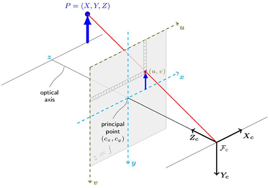
Pinhole camera model. 11
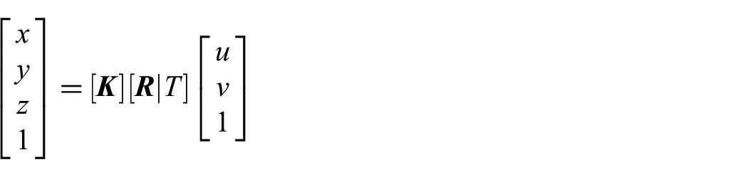
Next, a direct mapping can be made from 3-space,
2.3. Finding image features
Detecting specific and uniquely cross-identifiable features in images is paramount for SfM pipelines. Ultimately, feature matching is what allows for the recovery of camera position and orientation (pose).12–16 Other methods for recovering camera pose exist, they would be not be applicable to our intended application. 17 For SfM specifically, the detected features are the points that are triangulated between other images to create a sparse 3D reconstruction of the imaged scene, also known as a 3D point cloud.
2.4. Using features
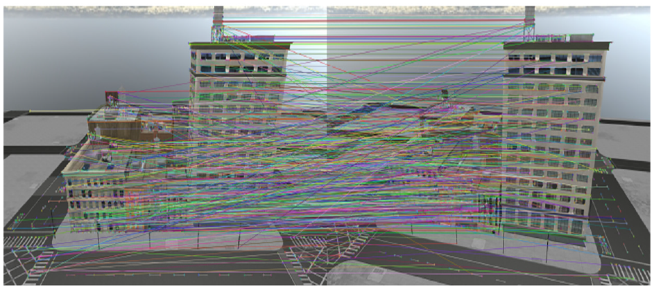
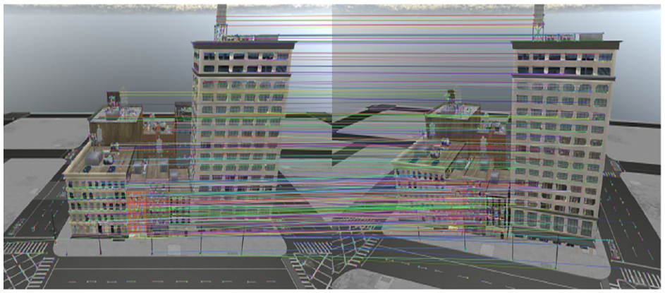
A set of features is detected within each image. These features are then compared with the discovered features in other images to determine image pairs as shown in Figure 3. However, the feature-pairs detected between similar perspectives are not all correct, and outliers must be removed before triangulation can occur. One method is to use a symmetry test to ensure the features found in image pair symmetrically point to each other, as these features were matched independently of one another. The results of the symmetry test are shown in Figure 4.
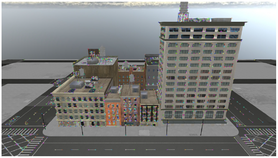
Visual representation of all features found in an image using the FAST feature detector.
Paired image features between two different perspectives after symmetry test.
2.5. Random sampling consensus to find essential matrix
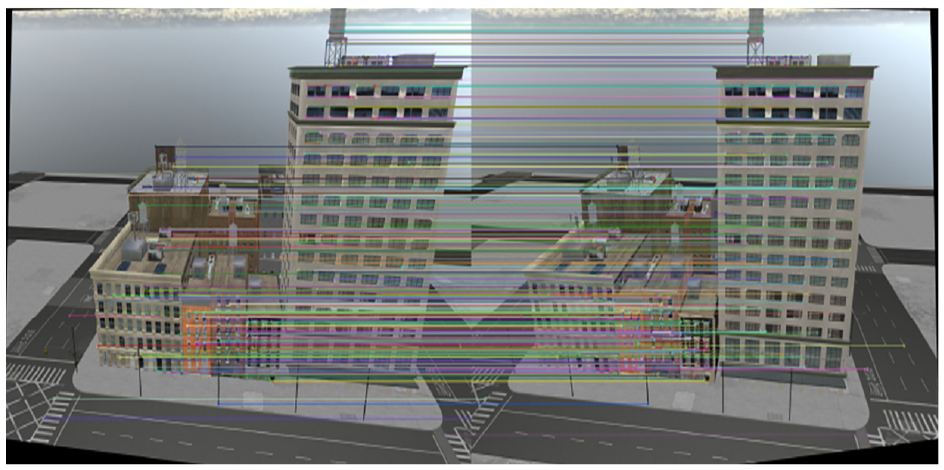
Even after the symmetry test, it is assumed that a considerable amount (approximately half) of all matched keypoints are considered outliers, which makes it difficult to determine a line of best fit when it comes to calculating the essential matrix. 18 However, the correct matrix can be approximated iteratively through random sampling consensus (RANSAC) by testing a random sampling of possible essential matrices for a pair of perspective projections. As a result, an essential matrix is also estimated for the camera pairs that can be used to further remove outliers in the paired perspective projections as demonstrated in Figure 5. With reference to Figure 5, all features are still present from the older images, but only matches that have been deemed as inliers now have corresponding randomly colored lines drawn between them.
Removal of outliers after applying RANSAC.
2.6. Extracting depth information
Epipolar geometry is the mathematical constraint used to extract depth information from perspective pair images and is the next step in performing point triangulation of keypoints in SfM. 19 Typically used to recover the depth information of stereo cameras with known rotations and translations, SfM is able to adapt the concept by treating the two separate images as a stereo camera, so long as the pose between the cameras is known (Figure 6).
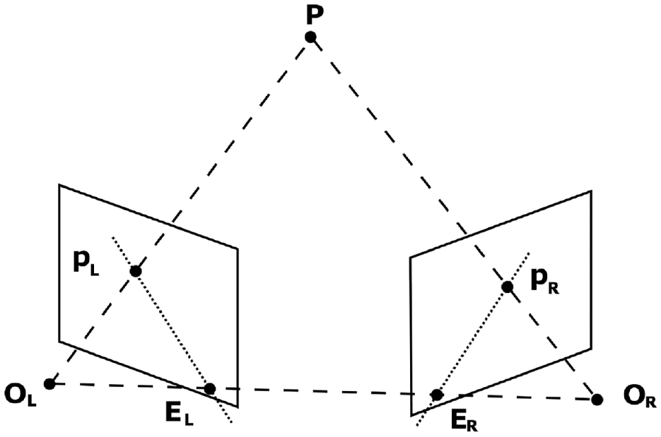
Epipolar geometry.
A useful optimization for triangulating points using epipolar lines is ensuring the lines are parallel and mathematically aligning the corresponding points such that either the x-component or y-component is constant (row-aligned or column-aligned pixels). This process is known as rectification, the result of which is shown in Figure 7. The black borders and warped images embedded in the border visually demonstrate the effects of rectification. The exact process of this mathematical alignment is discussed in greater depth in section 3.7.The rectification process distorts the perspective pair of images by mathematically flattening the two 3D image planes through a common double-width aperture to produce perfectly parallel epipolar lines. Once this is completed for each pair of images in the SfM toolset, 3D points can be triangulated. When the sparse reconstruction is complete in the form of a 3D point cloud from epipolar reprojection and triangulation, shown in Figure 8, with Figure 9 showing the truth model for reference.
Perspective rectification to create parallel epipolar lines.
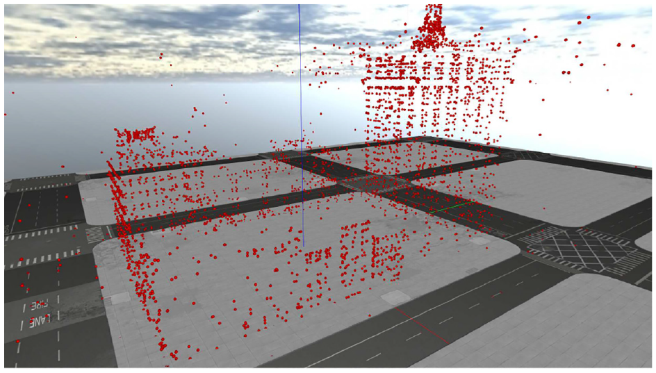
Point cloud with only ground model superimposed.
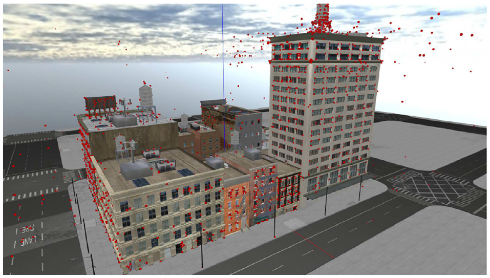
Point cloud with full truth model superimposed.
2.7. Further SfM steps
For the new method proposed by this paper, the remaining steps in SfM are not performed. Normally, after the sparse reconstruction is generated, the denser reconstruction is made. 20 Then the points in the dense reconstruction are efficiently connected to form a 3D mesh, which is then textured from the original source images to create the final reconstruction.21,22
2.8. Model size and orientation
One notable artifact of the SfM process is that all camera poses recovered via RANSAC computations are relative, meaning that it is impossible to recover the absolute positions of each camera without some external information. As such, the generated models typically have a random orientation and scale applied to them. This means that these models will require external information if they are to be useful for aerial reconnaissance. Correcting for orientation could be as simple as storing magnetic orientation of the camera, as well as ensuring each picture captured is aligned with a vertical axis based on the direction of gravity. Scale and translation of the image would be a more difficult process, but models could be compared to existing computed geometry for landscapes. Another solution would be to simply tag each camera position with a global positioning system (GPS) coordinate, but this approach lacks versatility in a GPS-denied environment.
2.9. Homography transformation
Instead of creating a dense reconstruction, refined mesh, and texturing that mesh, our proposed method deviates from the traditional SfM pipeline by replacing these functions with plane detection and homography transformation of the original imagery. We refer to the combination of these methods as PHE, which replaces the model texturing phase of traditional SfM.23,24 Homography is fundamental to producing visual perspective of a scene, and a homography transformation is a matrix transformation that enables the warping of perspectives in images. Homography is defined as a transformation between two planes as shown below: 19
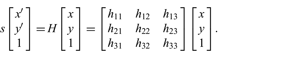
A homography transformation on a perspective projection image can be used to rectify portions of that image such that they align with a specific geometry. An example of this process is shown in Figure 10 showing the removal of perspective in reference to the rectangular portion of the building. Notice how the outlined rectangle in the right image is now parallel to the viewer’s image plane.
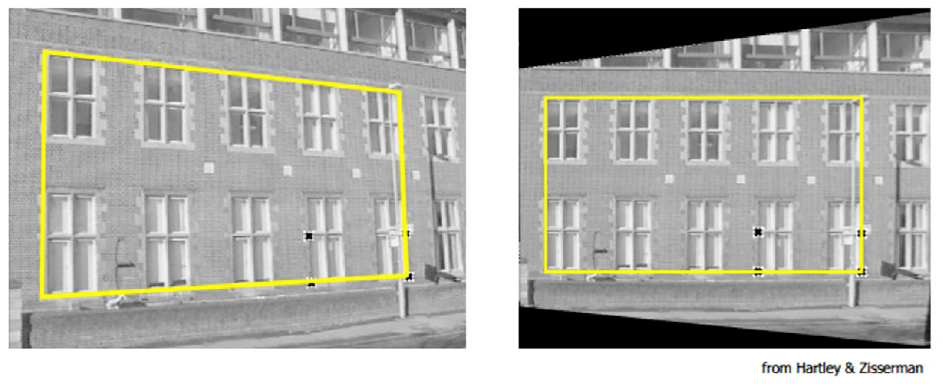
Perspective removal of imaged building façade. 19
2.10. Related work
This paper is a direct continuation of work performed by Roeber et al. 3 who demonstrated the use of SfM as a method of data compression for aerial imagery. Roeber’s results were extremely promising, showing a compression of nearly 60% compared to the original set of imagery. The largest two drawbacks in his approach were (1) the physical accuracy of the model, where distortion in the reconstruction was unintentionally introduced and (2) the large computational time required to create a 3D reconstruction from a set of captured images. Our work improves upon both these shortcomings.
While plane finding was chosen as the primary method to detect planes within the sparse reconstruction, another approach involves attempting to match basic object primitives to the geometry present in the sparse reconstruction. 25
SfM is a larger process that can be broken down into several smaller problems, with each step capable of being solved in many different approaches. In addition, most freely available SfM pipelines are composed of several smaller programs independently developed and combined as one. No single pipeline contains the best method for generating an arbitrary 3D model from images, each comes with trade-offs. This is best highlighted by the different choices made by designers for different underlying algorithms that accomplish the same task. For instance, in contrast to the Delaunay triangulation method for mesh model creation, the Poisson reconstruction method for generating a mesh model typically produces a model that is too detailed for aerial reconnaissance purposes, and pipelines using this method would have their defined use-cases specifically tailored to that type of modeling. 26
Another important decision in making an SfM pipeline is which feature/descriptor extractor to use; therefore, different analyses of the performance of each is important in choosing which one to use. According to an analysis of various image matching (feature detection) techniques, based on evaluations of Scale-Invariant Feature Transform (SIFT), Speeded-Up Robust Features (SURF), and Oriented FAST and Rotated BRIEF (ORB), ORB is the fastest algorithm but performance is slightly worse than SIFT. ORB is similarly comparable to SURF in most scenarios. 27 These results are also supported by another study of the computation time in OpenCV presented by Raquet. 28
A noteworthy finding from the study is that ORB tends to concentrate on features in the center of the image, while key point detectors for SIFT and SURF are distributed throughout the image. Another noteworthy finding is that ORB has a tendency to degrade in its feature detection capability when images forming angles larger than 45 degrees are used; therefore, it is important for this algorithm that the source images come from sets of images with small angular offsets between each image pair.
The SfM toolchain used for comparison against the SfM/PHE method proposed by this paper is a pipeline that combines the open multiple view geometry (OpenMVG) toolchain, used for feature matching, extraction, camera pose recovery, and sparse reconstruction, with open multiple view stereovision (OpenMVS), which generates and textures the final reconstruction model finishing the SfM pipeline.29,30These two tools are freely available, and relatively straight-forward to use. These toolsets were chosen over the ones used by Roeber et al. 3 because they can be seamlessly integrated through a python script, and can produce a full reconstruction without any manual input. However, the final model seems to be more prone to error, as the algorithm does not properly trim the model to the object of interest due to interference from the virtual world’s skybox, which consists of similar textures rendered as a static box around the camera based on the configured view distance in the virtual world.
3. Methodology
3.1. SfM with PHE
SfM in its current implementation is limited by its computational complexity, requiring up to 30 min to process 90 images in one instance. 3 We have rebuilt an SfM pipeline with real-time computation as the primary requirement, with the aim to transmit the generated 3D models in lieu of the live video with the hope to capture the bandwidth savings of traditional SfM. For this new variant, we employed the AftrBurner Engine 4 to leverage its OpenGL-based rendering 5 as well as its integration with the OpenCV 6 library. Together, this software platform can render virtual imagery, generate 3D models from the images, and quantify the reconstruction quality against the known truth model. All this can be done in a rapid, deterministic manner as shown in this paper’s corresponding video. 7
To achieve these speed improvements, the sparse reconstruction is constructed in a similar manner as traditional SfM, but leverages the Features from Accelerated and Segments Test (FAST) feature detector and the Binary Robust Independent Elementary Features (BRIEF) feature descriptor. Based on previous analyses, FAST and BRIEF show faster computation time compared to other methods.27,28 Next, we deviate from SfM by using a combined technique to detect planes within the sparse reconstruction and texture these planes through a process we call PHE.
The planes are detected via a RANSAC process, and then a homography matrix is computed that relates the 3D points of the detected plane projected onto an xy-plane with 2D coordinates of the features detected in the original images. The homography is then applied to one of the input images and this newly rectified image is textured across the plane. This process is repeated for each subsequent view. For an overview of the entire SfM with PHE process, refer to Figure 11.
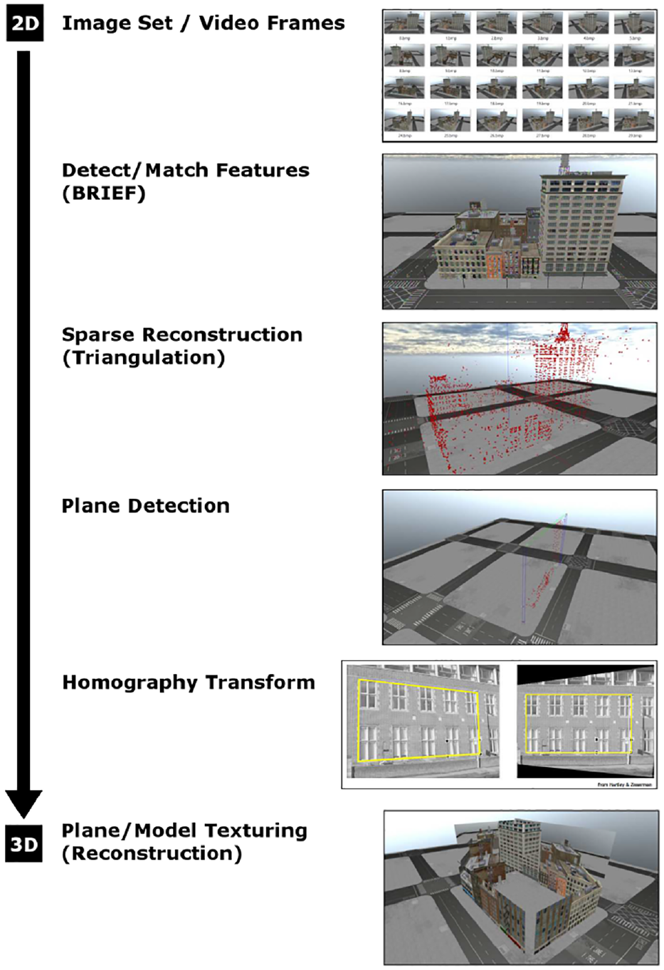
SfM with PHE overview.
3.2. Operating assumptions
Because the method is designed to run in real time, the variant will not have access to future images, so it is designed to work sequentially by only processing the feature matches found in the current and most recent images. This has the benefit of cutting out the lengthy
To facilitate ease of comparison and to eliminate a source of error in the new reconstruction, it is assumed that the exact camera position is known in model space within the AftrBurner visualization engine. The errors in determining camera pose from a set of features is well characterized. The process of making an estimation of the camera pose from the essential matrix is on the magnitude of single milliseconds, hence eliminating that calculation will not have a dramatic effect on the final computation time. Retaining access to the exact position of the camera also eliminates all issues with scaling and orientation of the reconstruction with respect to the virtual world, as all calculations can now be performed with the absolute translation and rotation. This further streamlines testing as a manual alignment of the reconstruction with the truth model no longer required.
The proposed method is a proof of concept; as such, it is currently only designed to handle specific types of truth model geometry. The method assumes that each model contains vertical walls, common to that of man-made structures, specifically because this algorithm is purpose-built for imaging man-made objects. Aerial surveillance is commonly performed in urban environments, so the assumptions applied to this model would be applicable for a surveillance regime that specifically targets man-made structures at human scale. However, this limitation is self-imposed and not representative of the ultimate capability of the proposed method, but merely as an approach to limit the scope of initial evaluation. However, with this limitation, detail is not lost in the final reconstruction.
Finally, based on initial camera calibration testing, the virtual camera used in the AftrBurner engine is well characterized, and to save time between tests, the intrinsic parameters and distortion coefficients are manually stored in the source code.
3.3. Virtual environment
When evaluating a new navigation-based algorithm, the ultimate goal is typically for real-world deployment; however, developing and testing in the real world brings a host of challenges including how to verify truth data, how to enforce flight path reproducibility, and how to close the loop for real-time decision-making when data are only collected for post processing, that is, no live data. Since this work focuses on early algorithmic development, these challenges can be postponed by using a virtual simulation environment. Such an environment offers solutions to all aforementioned challenges at the cost of synthetically generated sensed data. The closer these generated data approximate real data, the more accurate and predictive the virtual environment becomes. One defense-oriented virtual solution that has been used in several instances is the AftrBurner Engine. Kim et al. 31 used AftrBurner to generate monocular imagery for an optical flow–based unmanned aerial vehicle (UAV) navigation algorithm and was able to successfully use an embedded autopilot to navigate based on the virtual imagery. Lee et al. 32 employed AftrBurner to simulate stereo imagery for relative flight formation in the context of automated aerial refueling; his work presented results showing the predictive ability of stereo virtual imagery to be within centimeters of real stereo camera imagery capturing similar geometry. Parsons et al. 33 achieved similar results generating synthetic imagery for a vision-based proof of concept algorithm prior to several follow-up test flights at Edwards Air Force Base (AFB). The test flights confirmed Parson’s algorithmic viability and predictive ability of AftrBurner. Johnson et al. 34 merged synthetic imagery with synthetic satellite ephemerides to build an extended Kalman filter (EKF) within AftrBurner for close-flight formation. In addition, the AftrBurner Engine has been used to generate virtual imagery used to develop two US Patents35,36—one for an instrument to detect wake turbulence during flight and another to drastically compress an automated aerial vehicle’s remote-sensing data stream.
In our case, a virtual environment is the preferred method to test this new SfM implementation. Being able to quickly and accurately generate image projections from any perspective with an intrinsically known truth greatly decreases development time and cost. Deterministically repeatable data collections enable homogeneous comparisons across differing algorithmic implementations. There are many barriers to performing this type of experiment if limited to real-world hardware, such as obtaining licenses and permissions to operate a UAV to collect aerial images, and errors introduced through poor navigation that would cause each flight to slightly differ, thereby harming reproducibility. In addition, with a purely software solution, it is easier for others to verify the work demonstrated. Therefore, it is more efficient to perform preliminary testing in a virtual world to refine the process.
The scene used for experiments represents a city scape, with buildings ranging from a simple tall building to a complex set of 11 buildings on a single block. This is designed to test a variety of scenarios that may be present in an urban environment with many structures close together with varied geometries and urban environments with buildings that maintain larger separation. All these buildings are box-like, with some containing more complicated geometries, but all buildings imaged have vertical faces, which will be the target of the proposed SfM variant. This creates a varied test environment where the accuracies can be compared to that of traditional SfM, as well as to the original truth model. Figure 12 shows the geometry of the most complex truth model that will be tested. This truth model is similar to the demonstration of SfM as a data compression method by Roeber et al., 3 where the only difference is that the ground model has been aligned with the building.
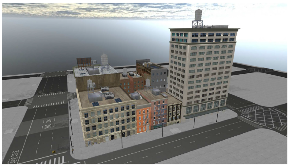
Truth model rendered in AftrBurner.
Finally, the image collection apparatus is represented by a small UAV model that flies around the test environment and captures virtual images of the truth model. The camera is simulated based on the pinhole camera model.
3.4. Input data collection
A circular flight path that orbits a central point was chosen as the method of data imagery collection with 30 evenly spaced images. This serves the purpose of ensuring that every face of the model is imaged equally. This creates a best case scenario for creating a well-matched point cloud, which can be used to detect vertical walls, represented as vertical planes in the scene. The flight path is inspired by the previous work of Roeber et al. 3 and Ekholm, 37 who used similar flight paths to gather imagery of the truth model.
However, this flight path differs from that of Roeber in the sense that it is a purely circular orbit with no spiral pattern. The flight path is a predefined orbit with parameters for the altitude (meters), radius (meters), and the number of images collected. In addition, the orbit requires a desired target, which in this case is defined as the point of surveillance for each captured image. Figure 13 shows a standard flight path around a truth model, and each perspective projection is represented by a camera frustum originating from a point along the flight path. Figure 14 shows an example of captured images using the described orbit.
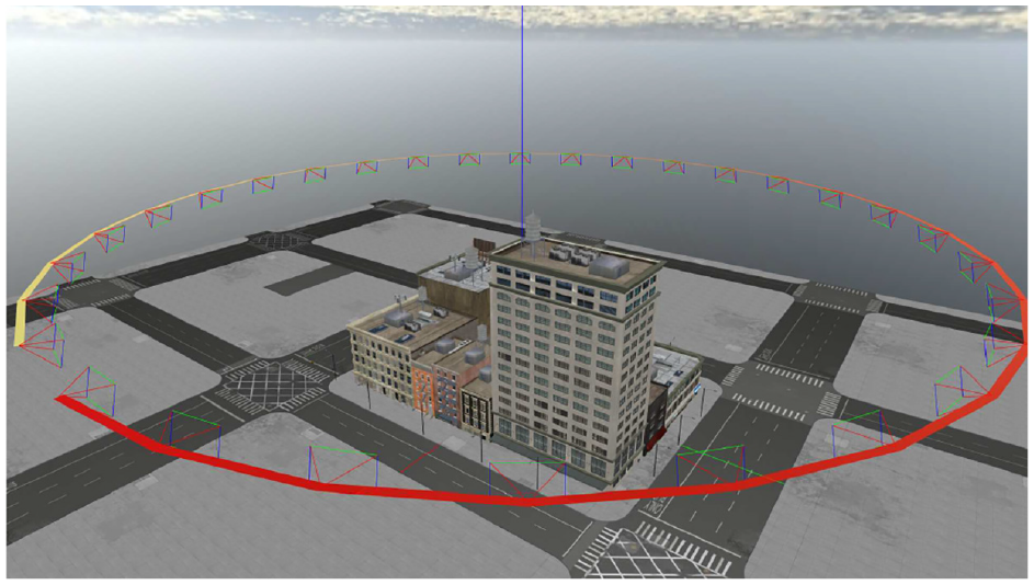
Standard orbital flight path with camera frustums.
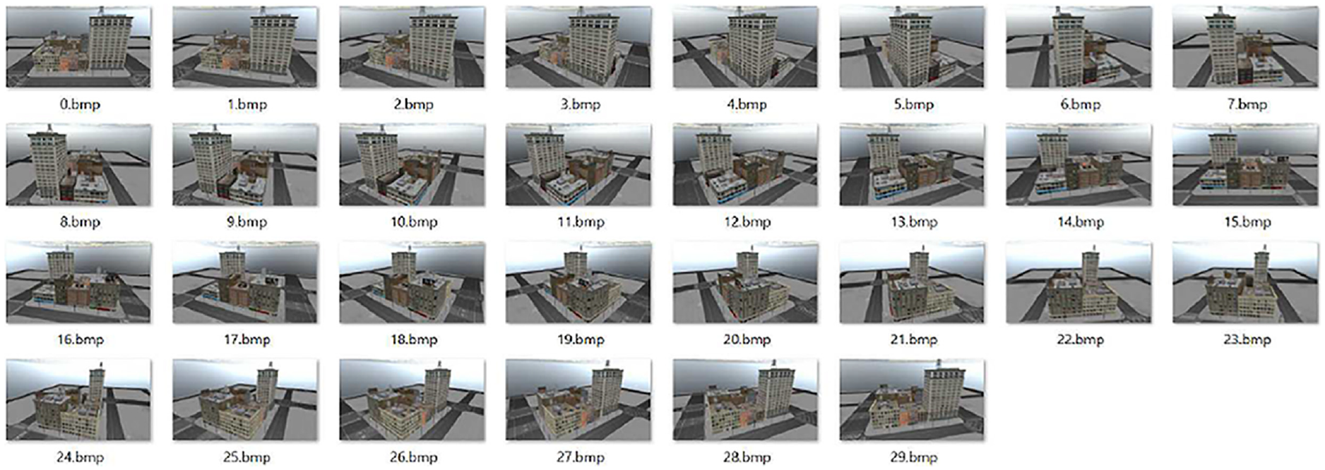
Example of images collected by virtual camera to be used for feature matching and plane texturing.
3.5. OpenCV point triangulation
From the row-aligned features, we triangulate those matches and create a sparse reconstruction in the form of a 3D point cloud. This is done through the cv::triangulatePoints function in the OpenCV library along with some additional logic to convert between the OpenCV reference frame and AftrBurner visualization engine. Point triangulation is a derivative of stereo imaging, as such it relies on the past work of Hartley and Zisserman, 19 Trucco and Verri, 38 Forsyth and Ponce, 39 and Shapiro and Stockman. 40 Figure 15 shows the result of the point triangulation in the form of the sparse reconstruction. With this, we now have the general size and shape of the structure.

Reprojected points without model.
3.6. Plane finding
Using the sparse reconstruction, we approximate the geometry of the scene with large generalized vertical planes. To find planes within each feature matching set, using a unique RANSAC process, our algorithm randomly picks three starting points and counts how many points fit along that plane. Checks are made to avoid collinearity among the three points.
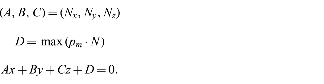
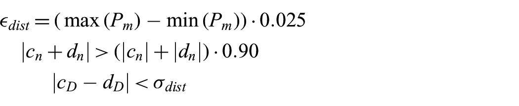
Other intrinsic errors are introduced in the process of extracting the 3D geometry of the scene, and the algorithm accounts for these variations through a threshold to determine coplanar and colinear points. These thresholds are dynamically computed based on given inputs for the size of the scene imaged. This is done by computing two vectors,
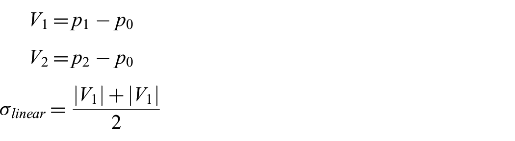
where

Once three physically separate points are chosen, then the number of points that are members of the chosen plane are counted. This is done by computing a third vector,
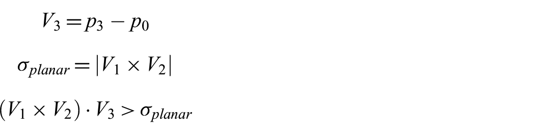
This RANSAC plane detection process is repeated for twice the number of 3D points present in the point cloud to ensure the accuracy of the detected plane. Each iteration checks for the plane with most members and stores the largest set as the best plane. Figures 16 and 17 show the results of this process. The bounding boxes for the point clouds are enabled and they demonstrate how large the original point cloud is before the plane detection occurs.
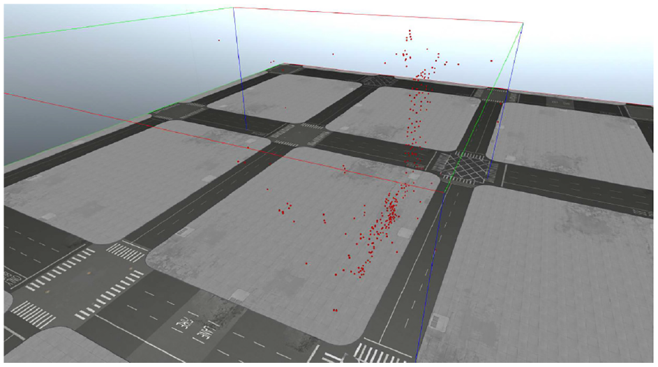
Point cloud of one perspective before plane detection.
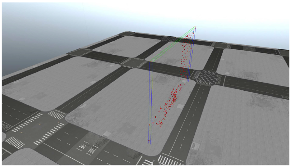
Point cloud of best plane detected from one perspective projection.
Next, a check is made to ensure the detected plane is a vertical wall. This is done by comparing the z-value of the computed normal vector,
Next, the displacement component of the plane,
Finally, the best plane detected by RANSAC is compared against previously detected planes from different perspectives to determine if it is a duplicate. Further computations for a plane that has been previously detected in the scene is unnecessary unless the newer detected plane is better than previous ones. First the normal vectors for the candidate plane,
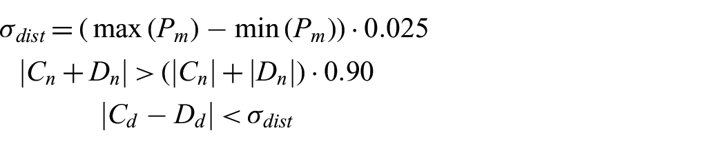
However, if the candidate plane contains more 3D points, it will be added to the list of detected planes and replace the previous plane that is similar to it.
In this implementation of the method, only one plane is detected between two perspective projection pairs. It could be altered to detect further smaller planes present in each pair, but for simplicity of testing, only the most prominent plane in each pair is needed.
The RANSAC plane finding method used for our proposed variant is but one alternative. Another common approach involves attempting to match basic object primitives to the geometry present in the sparse reconstruction. 25
3.7. Homography transform and texturing
Next, we create a texture to apply to the newly discovered planes. We use the cv::findHomography function call to compute the homography transform between two sets of points; 41 however, the point sets need to be represented as a 2D array of xy-points in an image. The first set can be directly derived from previous computations where the 2D feature keypoints were computed in the image, but the second set must come from the 3D points. In this instance, the 2D feature keypoints represent the previously warped perspective, and the 3D points can be altered to represent a perfect planar projection of a desired area in an image. In this case, the desired area is the vertical face of a building, described previously as the detected plane in the sparse reconstruction.
For this, the 3D points from the plane can be mathematically reprojected as 2D members of a rectified xy-plane,

Thus, the x-component can be computed as the cross-product of the normal vector of the plane and the y-component,

Next, the corners of the 2D projection are derived from the 3-space min and max points present in the detected plane, where the bottom left and top right corners,

and

It is unknown exactly how the plane is oriented in 3-space, so a simple sign modifier for the x and y components of each 2D point is computed as follows:
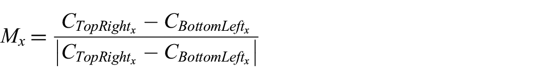
and
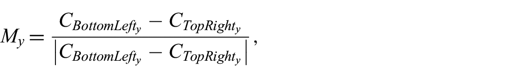
which is then applied to the respective components of the corners and to the 2D projection of the remaining points in the detected plane. The 2D projection for each point,

and

Next, the scale and offset for the projected points need to be computed as they exist in a different reference frame from that of the original perspective projection pair. This is done by computing vectors,

and

where the scale,
and

The scale and offset can then be applied to all the points in the detected plane. At this point, the two sets of points are ready to be used to calculate the homography matrices for the left and right perspective projections.
Then, we apply the computed homography to the original images, which warps the perspective of the original image as a fully rectified texture. Figures 18 and 19 show the results of the homography transformation to visually align the detected plane with the viewer’s image plane. The black borders and warped images embedded in the border visually demonstrate the effects of rectification.
Before homography transformation.
After homography transformation.
Finally, the image is then cropped to the size of the detected plane and used as a texture for the quadrilateral object in the reconstruction.
3.8. Plane refinement
If a better plane is discovered that occupies the same location as another plane, it must be replaced. A simple method that only replaces the reconstruction quadrilateral,
A similar check as the plane detector to find similar planes among the plane that is to be added to the reconstruction model is given by:
The above equation determines if a candidate plane and an existing plane share similar normal vectors and displacement components. If this is the case, then an additional check is performed to verify that the planes themselves overlap, which is as shown below:

and

If either
Once all the perspective projection pairs have been processed, the reconstruction for SfM with PHE is complete.
3.9. Generating traditional SfM reconstruction for comparison
For an evaluation of the efficacy of using SfM with PHE, a traditional SfM reconstruction is also generated to be used for comparison. This is done using the OpenMVG and OpenMVS pipelines linked to each other through a python script.29,30 The exact same input images are used in this pipeline, using the same intrinsic camera parameters.
Care is taken to ensure that the alignment of the traditional SfM reconstruction matches the truth model for the best possible spatial comparison.
3.10. Evaluation criteria
Multiple comparisons are made for each data set. First a data size comparison between the storage size of the input images, the size of traditional SfM reconstructions, and the size of the SfM with PHE reconstructions will be done. This allows us to understand bandwidth transmission needs for real-time UAV scanning on target.
Next, a computation time analysis is performed, measuring the length of time required to complete a traditional SfM reconstruction and a new SfM PHE reconstruction. This allows us to understand the size, weight, power, and cost requirements to run this algorithm on a UAV.
Finally, both the traditional and PHE reconstructions are assessed for their spatial accuracy by using virtual georeference points, which has also been used in related works.3,42,43 The georeference points are manually chosen key points in the truth model, and the same points are mapped similar to both reconstructions. A sum-of-squared differences is used as the error metric, where a lower number corresponds to better spatial accuracy. For this experiment, the XYZ error is tested.
4. Results and discussion
4.1. Hardware/software environment
The experiments were conducted on a Thinkpad P51 laptop similar to the hardware used by Roeber et al. 3 The laptop employed an Intel i7-7820HQ CPU clocked at 2.90 GHz, with physical 4 Core, 8 Logical Processors using Intel Hyperthreading, and 16 GB RAM. OpenMVG and OpenMVS support multi-threaded processing, so they will have a small advantage over the SfM PHE method which currently does not implement multi-threaded computations. However, a future implementation of this method could be capable of multi-threading. Traditional SfM also uses smaller texture sizes for various parts of the reconstruction geometry, whereas SfM with PHE still uses full-size images.
4.2. Datasets
Each dataset assumed only one circular orbit for image collection in contrast to the previous work by Roeber et al., 3 where multiple helixical orbits collected more imagery than our experiments. The datasets generated in these experiments are similar to an actual reconnaissance flight path. Because of this, noticeable degradation in the model accuracy of the traditional SfM reconstructions was observed. Work done by Roeber demonstrated that the exact flight paths did not have much of an effect on the final model.
Each flight path collected images along a fixed radius around each model. For instance the Arab House flight path is an orbit around a smaller building at a lower altitude—effectively testing what the algorithm might produce when a surveillance platform is used at the same elevation as the observed structure. Whereas the Tall Building and the City Block models demonstrate a flight path from a reconnaissance platform flying high above a city. No specific flight path was chosen because it was the best one for that environment, but it was merely chosen based on the best ability to capture the entire object in one image.
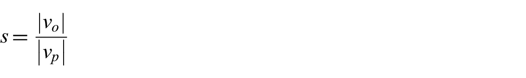
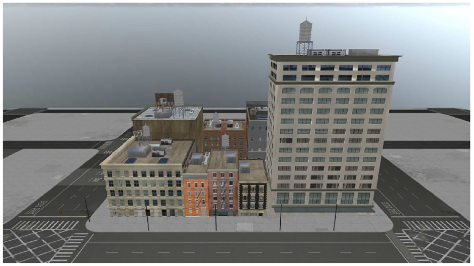
Geopoints were collected manually by finding easily identifiable features between the truth model and reconstructions. Typically, this meant various windows and building corners present in the scene. An example of this process is shown in Figures 20 and 21. Yellow and orange points are visible in these pictures, with yellow indicating the geopoints for the reconstruction and orange for the truth model. In this example, the orange geopoints are very difficult to see as they line up near perfectly with the yellow geopoints.
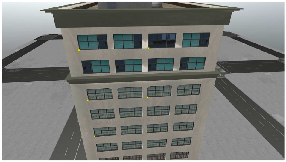
Example of geopoints on truth model, notice yellow dots in low left corners of windows.
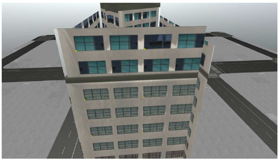
Example of geopoints on PHE reconstruction.
5. Discussion
Comparisons on the reconstructed models’ data size, computation time, and spatial accuracy were made. For every reconstruction with and without PHE, the size of each model was significantly smaller than the original image set containing 30 different perspectives. However, PHE differed from traditional SfM in that it performed its task much faster, achieving significant speedups, up to 80× that of traditional SfM. Based on visual inspection, the traditional SfM appeared to be less spatially accurate than PHE, however, for instance where PHE failed to properly find a plane, or where objects behind the plane were included in the texture, PHE accuracy fell. Also, a metric analysis was not performed for the Arab House due to the absence of easily identifiable features to measure on the traditional SfM.
The Arab House proved to be the most difficult for both algorithms to create reconstructions as the virtual model was very simplistic and contained many repeated features, but the PHE reconstruction approximated the underlying geometry better than the traditional SfM reconstruction. In addition, several of the reconstructions built with traditional SfM had to be recomputed, due to very large distortions present in the reconstruction. This is probably due to the automated algorithm that chooses what is the most prominent object in the scene, and it is likely that the static environmental background was causing these errors. This is supported by Roeber’s previous work, where the background was intentionally left blank due to errors it introduced.
Because this algorithm is only designed to work for vertical walls of man-made structures, the roofs of these structures are noticeably missing. This was an intentional design decision when building the algorithm, and because an implementation was not made that estimates the full geometry of an object based on its point cloud. This is a separate component to the problem that is left as future work.
5.1. Tall building
The singular tall building shown in Figure 22 represents a best case for this specific implementation of PHE, as it contains a singular cuboid geometry. Future implementations could include better imaging algorithms to trim planes to the specific geometry of complex objects.
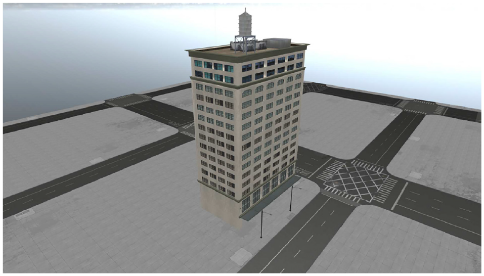
Tall building scene with only the truth model visible.
PHE was able to achieve the greatest compression with the tall building, compressing the final reconstruction 97.74% smaller than the original 30 image data set, all while doing it in approximately 7 s. If use for a video feed is assumed, then for this instance, PHE would be able to process the scene at four frames per second.
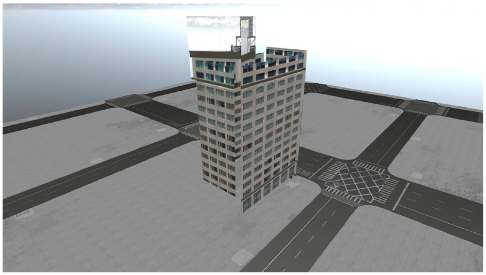
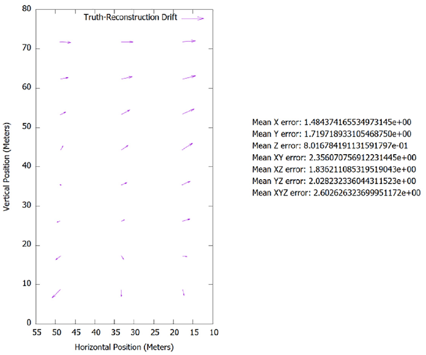
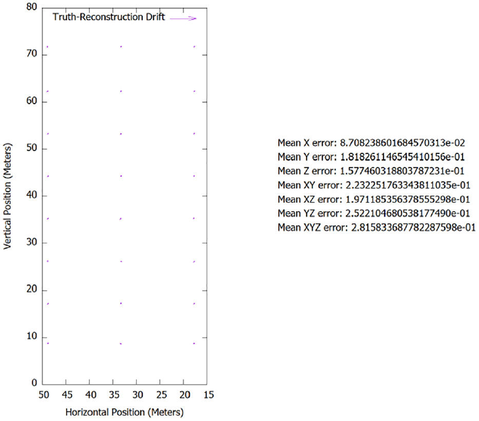
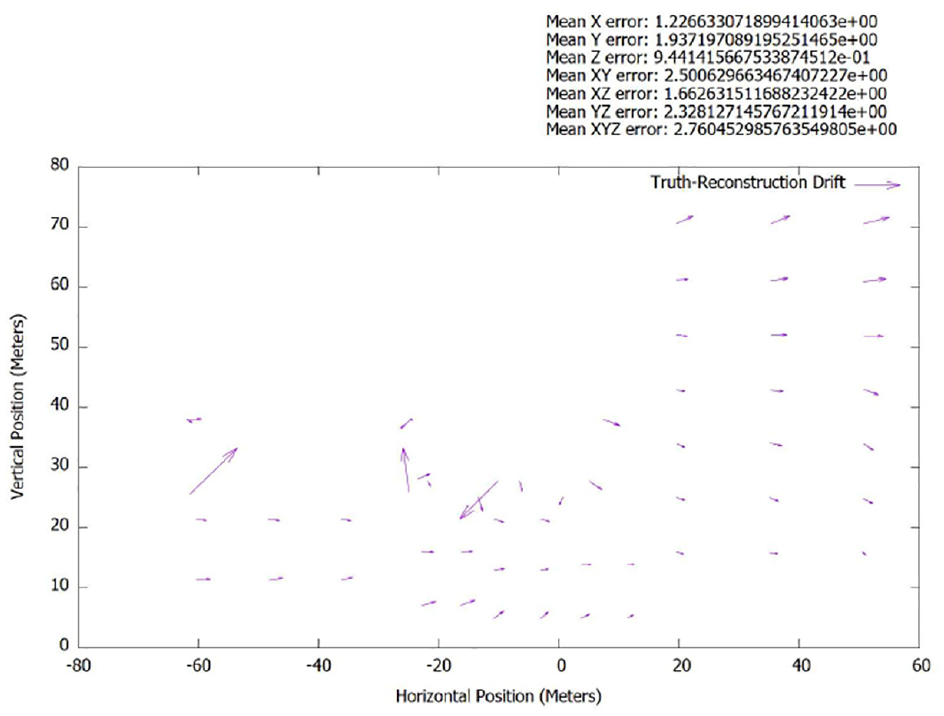
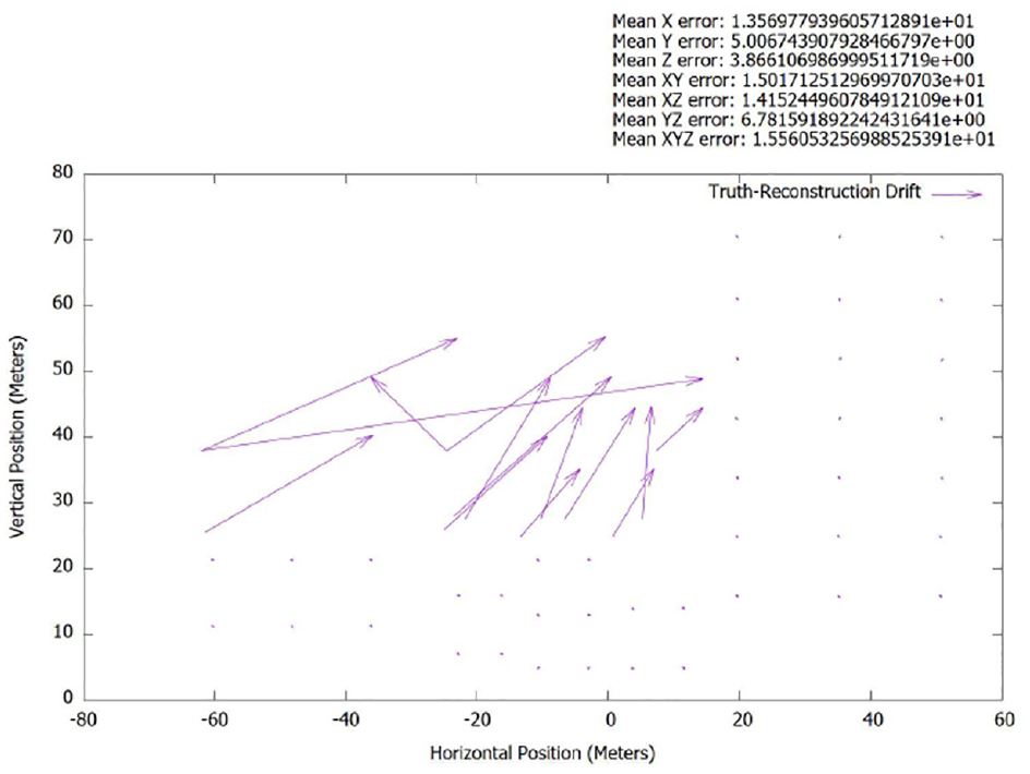
Even though the full geometry is not represented by the PHE reconstruction, what was represented matched the truth model nearly perfectly, showing little to no error, see Figure 23. More error was likely introduced through the manual process of collecting the geopoints than due to inaccuracies in the reconstruction. In contrast, the traditional SfM reconstruction had a significant lean present in the model, in addition to the model appearing very rough in general. This observation is supported empirically by Figure 24 and through visual inspection of Figures 25 and 26.
Tall building metric analysis of spatial accuracy of x-face between truth model and PHE.
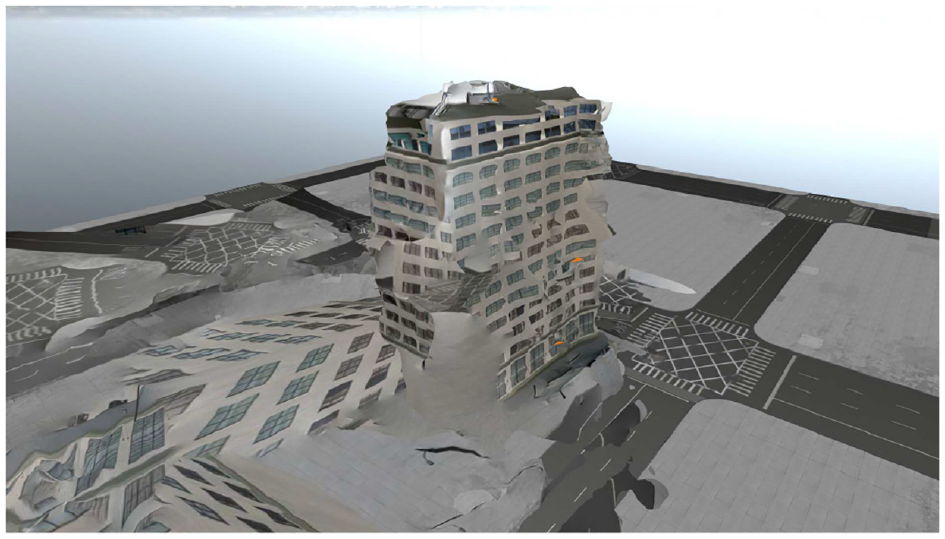
Tall building metric analysis of spatial accuracy of x-face between truth model and traditional SfM.
Tall building scene with only the traditional SfM model visible.
Tall building scene with only the PHE model visible.
For a more in-depth view of the tall building model and the resulting reconstruction, please reference timestamps 3:22, 3:31, and 3:40 in our video. 7
5.2. City block
The city block represents a typical use case for aerial surveillance on man-made objects. It contains many buildings with various and complex geometry. In its current implementation, PHE reconstructions might not be fully adequate to replace the video feed for aerial reconnaissance, showing its limitations to only find simple rectangular planes to texture. However, for the areas that are represented in the reconstruction, they are more accurate than that of traditional SfM, which is prone to greater distortions. In addition, the PHE reconstruction might also be limited by the nature of the virtual model, which contains fewer physical features for the feature matcher to recognize. So the limitations present here may not fully represent its capability with real-world imagery.
Nonetheless, the storage size of the model was still smaller than both the original data set and the traditional SfM reconstruction; PHE was computationally faster as well. This is expected as the reconstruction is composed of —four to six planes with homographied textures. Similar distortions are present in the traditional SfM reconstruction as shown in Figure 27 and supported empirically by the graphs in Figures 28 and 29, whereas the PHE reconstruction had no such distortions present.
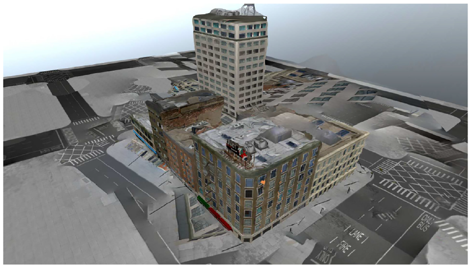
City block scene with only the traditional SfM model visible.
City block metric analysis of spatial accuracy of x-face between truth model and traditional SfM.
City block metric analysis of spatial accuracy of x-face between truth model and PHE.
For a more in-depth view of the city block model and the resulting reconstruction, please reference timestamps 3:25, 3:33, and 4:00 in our video. 7
5.3. Arab house
The Arab style house demonstrates how PHE might perform with images taken from street level, where the geometry of the roof may not be known. Typically, this is also accomplished easily by traditional SfM algorithms, but in this instance, the model textures were so similar that they resulted in many inaccuracies in the reconstruction process; as such, only a partial model was recovered.
Interestingly, the size of the traditional SfM reconstruction was smaller than that of the PHE reconstruction; however, this may be attributed to the incomplete reconstruction that was generated. Even though the PHE reconstruction was larger than the traditional SfM reconstruction, it was still significantly smaller than the data set, and the computation time of PHE was still much faster than traditional SfM.
For a more in-depth view of the Arab house model and the resulting reconstruction, please reference timestamps 3:28, 3:35, and 4:16 in our video. 7
6. Conclusion and future work
6.1. Conclusion
(1) This paper contributes a novel algorithm—SfM with PHE. This algorithm leverages the intrinsic properties common to many man-made structures, such as vertical walls, to more rapidly and accurately create a texturized 3D model of an environment. (2) As quantified in Table 1, our algorithm is capable of running at 4 Hz, approximately 80× faster than traditional SfM approaches using a commodity laptop. (3) Our algorithm outputs a texture-mapped, low-polygon 3D model of the scene in lieu of transmitting an entire image set. As shown in Table 2, this achieves compression ratios 88.9%–97.7% higher than traditional SfM. (4) Finally, the texturized 3D models are as accurate, or, in our presented cases, up to 10× more accurate than traditional SfM approaches. Our spatial analysis as in Figures 28 versus 29 and Figures 25 versus 26, shows that the accuracy of features lying on our generated 3D model is approximately an order of magnitude more accurate than a traditional SfM approach. The accuracy is high enough that a remote operator could simply click a location on the 3D model, acquire the corresponding global 3D coordinate, and submit that 3D coordinate for intelligence purposes or additional mission vectoring.
Computation time comparison.
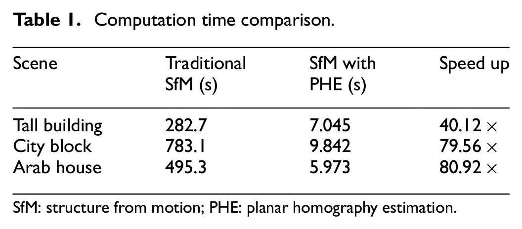
SfM: structure from motion; PHE: planar homography estimation.
Storage size comparison.
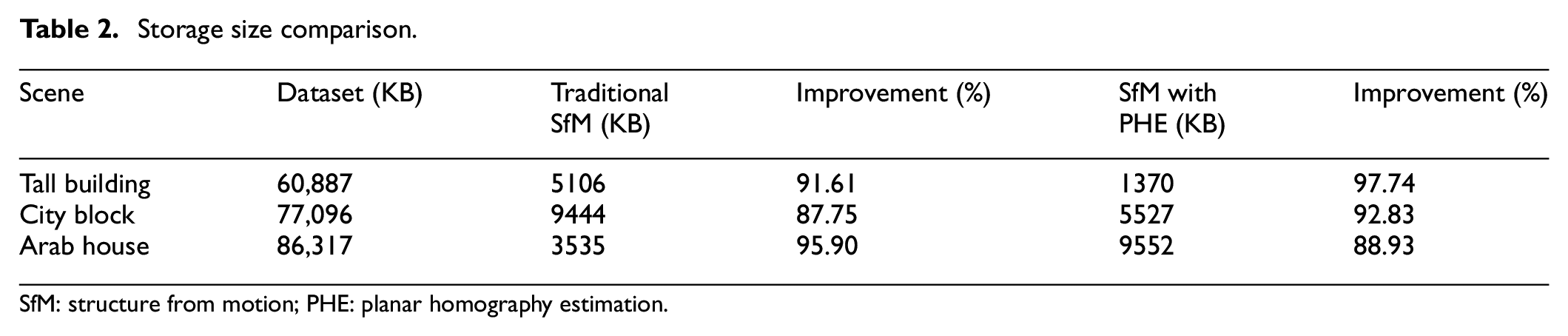
SfM: structure from motion; PHE: planar homography estimation.
This system was built with computational speed in mind, and we were able to achieve operation at 4 Hz providing data similar to traditional SfM algorithms at a fraction of the computation time and space. This demonstrates its potential for use to augment or replace video imagery. This work enables ability to pre-process imagery into a smaller 3D model that is transmitted from a UAV to remote operators.
The speed at which this method was developed would not be possible without the strategic use of virtual environments and a graphical visualization engine to test our new method. The use of a virtual environment enabled the repeatable analysis of information in a deterministic manner, eliminating many sources of error. The virtual world also enabled a cost-effective testing environment, as no physical hardware other than a laptop was needed to conduct each experiment. In addition, the experimental environment for each test was not subject to real-world problems such as weather and logistical flight coordination to collect aerial photography, as well as the regulatory process that would be necessary to accomplish these tasks.
Many metrics were used to measure the effectiveness for SfM with PHE versus traditional SfM and a standard data set with no size reduction to simulate the requirements for a video feed. From the data collected, SfM with PHE shows promise, but requires further development before it can be used as an alternative to traditional SfM or replace video imagery. However, it does come with the benefits of creating a 3D model that reflects greater spatial accuracy of the scene versus traditional SfM, and is able to create a reconstruction in a timely manner that would be acceptable for aerial reconnaissance, depending on the application. The model created is so accurate that it could also be used to generate GPS coordinates for specific features of the building imaged.
6.2. Future work
There is still much work to do, and many different areas are ripe for improvement. To improve spatial accuracy, further exploration of image processing algorithms to detect the edges of a rectified face of a building could be used. Ideas such as using Hough lines and pixel comparisons between different frames were explored as part of this research, but ultimately not included as an adequate working model was not achieved in a timely manner. Other exploration could look into using the images parallax as a means to determine what parts of the image belong to the detected plane, and what parts of the image lie in front of or behind the rectified plane.
To improve the computational time required for this method further, multithreading strategic areas of the algorithm that perform repetitive tasks could be beneficial, but was not explored as part of this research. Furthermore, it should be possible to accelerate computations via a graphical processing unit in some areas of SfM with PHE. This is possible due to many sections in the algorithm where calculations are performed on a pixel-by-pixel level, and would benefit greatly from vectorized execution.
More varied flight paths should be tested in the future, like a point-to-point flight path that can specifically mimic data collection in an urban canyon as the drone flies over streets between buildings.
An analysis of the energy required to run this algorithm was not performed, which would be important if this is designed to run on a remote device that is reliant on a finite energy supply. However, evidenced by the short computation times, it is unlikely that SfM with PHE would have a dramatic energy usage for an aerial surveillance platform. Furthermore, energy usage could be improved via intelligent implementation of accelerations by low-energy graphical processing units such as an Nvidia Jetson TX-series.
In addition, SfM with PHE could be improved via mipmapping, reducing the sizes of textures, as the majority of the reconstruction storage size is due to the size of the images. There are arguments to be made that if reducing the image resolution is possible, then it should also be possible with the source imagery. While this is true, having access to the 3D aspect of the reconstruction means that much less texture information is required to convey the same meaning to an intelligence analyst as traditional 2D images.
Further aim is to make the algorithm more robust, beyond just identifying and reconstructing vertical walls. SfM with PHE should be capable of handling a variety of geometries, and more importantly, completing the geometry of imaged objects, such that roofs and building corners. Included in this should be determining the feasibility of long-range sensory imagery for SfM, where the remote sensor is hundreds of kilometers from its target, like that of a satellite. Some imaging regimes will not involve a remote asset that is able to get in close with the target object.
Finally, real-world tests must be performed once much of the above is explored or implemented. While traditional SfM has proven effective for real-world objects, and there is sufficient reason to believe that SfM with PHE would perform similarly, it is also important to fully characterize the algorithms behavior and make potential tweaks to handle instances under non-ideal conditions, such as excessive shadows or glare.
Footnotes
Funding
The author(s) received no financial support for the research, authorship, and/or publication of this article.