
Abstract
The Tufts New England Regional Biosafety Laboratory facility has been using chlorine dioxide gas for >5 years, and >100 decontaminations have been done at the room level and on a Class III cabinet. The rooms have ranged from animal holding rooms containing animal racks (housing rodents and rabbits), biosafety cabinets, and computers to biosafety level 3 laboratories containing a variety of equipment (microscopes, biosafety cabinets, centrifuges, incubators, real-time polymerase chain reaction machines, etc). For a biosafety level 3 facility, the equipment is stainless steel where possible, but there is a variety of materials, including electronics and other sensitive equipment. No corrosion has been experienced on any equipment or surface despite repeated decontaminations. Even the most sensitive equipment has not experienced any ill effects. As a test, when decontaminations were started, a low-cost laptop computer was moved from room to room to a Class III cabinet, decontaminating it every time in each chamber. After 35 repeated exposures, it was still functioning with no issues. It is still in use in one of the animal rooms and gets decontaminated along with the room. The Class III cabinet has not shown any traces of corrosion on the stainless-steel interior, nor has the stainless-steel inhalation exposure system kept inside the cabinet experienced any ill effects.
Facility Background and Capabilities
The Tufts New England Regional Biosafety Laboratory (RBL) is a 41 000-ft2 resource available to researchers in industry, academia, government, and not-for-profit. It is dedicated to the study of existing and emerging infectious diseases, toxin-mediated diseases, and medical countermeasures important to biodefense. The RBL is a regional resource that allows researchers to improve human health through better detection, prevention, and treatment of infectious diseases.
Investigators at the RBL include members of the Department of Infectious Disease and Global Health at the Tufts Cummings School of Veterinary Medicine who are experienced in many areas of research, including the biology, transmission, prevention, diagnosis, and treatment of infectious and toxin-mediated diseases associated with National Institute of Allergy and Infectious Diseases priority pathogens, food- and water-borne illnesses, and food and water security. The RBL is available as a resource to investigators from other academic institutions, not-for-profit organizations, and the private sector in New England and nationwide.
The RBL, as part of Tufts University and the Cummings School of Veterinary Medicine, offers access to experienced investigators with expertise in the following: in vitro assays, assay and animal model development, biosafety level 3 (BSL-3) and select agent pathogens, study design and protocol development, and regulatory aspects (biological select agent and toxins, good laboratory practice, investigation new drug, Department of Defense). It includes laboratories for the study of BSL-2 and BSL-3 agents, including select agents. In addition to BSL-2 and BSL-3 laboratory suites, the facility features an animal BSL-3 vivarium, aerobiology suite, and insectary.
The BSL-2 laboratory area features a separate tissue culture room that can be used under positive or negative pressure, depending on the type of work being done. Each laboratory is fully equipped and includes refrigerators, freezers, high-speed centrifuges, bacterial incubators/shakers, CO2 incubators, spectrophotometers, polymerase chain reaction thermocyclers, vortexers, pipettors, ELISA plate readers, and washers. The suite also features an ultracentrifuge and a Class II, type A2 biosafety cabinet (BSC).
The BSL-3 area of the RBL contains 3 laboratory suites: 2 with a shared autoclave and 1 with a dedicated autoclave. Each laboratory is fully equipped and includes refrigerators, freezers, high-speed centrifuges, bacterial incubators/shakers, CO2 incubators, spectrophotometers, polymerase chain reaction thermocyclers, vortexers, pipettors, ELISA plate readers, and washers. Equipment featured in this area includes Class II, type A2 BSCs; 1 Class II, type B1 BSC (30% recirculated, 70% exhausted); and gowning and shower vestibules.
The vivarium is designed for animal BSL-3 work. It includes the animal holding areas, as well as the aerobiology suite and insectary. Each holding suite features room for 4 racks per suite, with in-room procedure areas and BSCs. Features within the vivarium include ventilated cage racks for housing rodents, rabbits, and ferrets, as well as gnotobiotic piglet isolator housing, automated watering systems, a tissue digester, cage and rack washers, feed and bedding storage, and 2 large-capacity autoclaves.
The aerobiology suite is designed for the study of the air-borne transmission of pathogens, aerosol delivery of therapeutics, and aerosol challenge studies. Key to this area is a Class II, type A2 BSC connected to a Baker Class III glove box. Inside the cabinet is a nose-only inhalation system (CH Technologies, Westwood, New Jersey).
The insectary portion offers expertise in all facets of vector biology. In particular, scientists here can maintain the life cycles of most arthropod vectors as well as those of diverse arboviruses, bacteria, protozoa, and helminths of medical importance. Natural transmission models with infected arthropod challenge are critical to the understanding of the initial events of infection and pathogenesis, as the bite site is immunomodulated by vector saliva. Scientists here have extensive experience with:
deer tick-transmitted infections such as Lyme disease and Borrelia miyamotoi tick-borne disease, babesiosis, human anaplasmosis, deer tick virus; Lone Star tick-transmitted diseases such as Masters disease/southern tick-associated rash illness, human monocytic ehrlichiosis, rickettsiosis; and dog tick-transmitted infections (Rocky Mountain spotted fever, tularemia).
In addition, mosquito challenges can be conducted with West Nile virus, eastern equine encephalitis, and California group arboviruses or with Plasmodia spp or filariid nematodes. Transmission models of Leishmania spp by sandflies or Trypanosoma cruzi by reduviid bugs may also be easily developed.
Decontamination Choices
The 2 main processes are vapor-phase hydrogen peroxide (VPHP) and chlorine dioxide (CD) gas – both decontaminate effectively. Both systems can be used safely if one follows the manufacturer's recommendations, performs preventive maintenance on the equipment as needed, and obtains the proper training, both systems can be used safely. But, of course, users need to have safety gear on hand and ready just in case.
Which system is best? It depends on what needs to be decontaminated and what the facility is designed for and can handle. Both VPHP and CD have their advantages and disadvantages. CD easily penetrates and distributes into all spaces. It covers an entire room, penetrates deeply into equipment, and gets into the hard-to-reach places. It penetrates well into high-efficiency particulate air (HEPA) caissons/filters and easily decontaminates duct work. Setup is simple and requires very few extras (only 1 or 2 fans and a portable humidifier).
Based on the needs to decontaminate this RBL and its projected future expansion, CD gas was the best choice as it provided complete decontamination of all surfaces within the spaces and inside the Class III BSC. All cycles were efficacious such that all biological indicators (BIs) were repeatedly killed and no issues of corrosion were evident.
Since this facility was built to work with infectious diseases, decontamination became a very important aspect of the facility. Formaldehyde was not considered due to its carcinogenic and residual aspects. Note that formaldehyde is considered a probable human carcinogen by the US Environmental Protection Agency 1 and is classified as a carcinogen to humans by the International Agency for Research on Cancer. 2 When neutralized in place, the residue (either paraformaldehyde or methenamine 3 ) must be cleaned from all work surfaces. If formaldehyde is exhausted, a postexposure wipe-down may not be required. Residual formaldehyde due to off-gassing from the paraformaldehyde is a concern because of its toxic and irritating properties and potential for adverse effects on the research being conducted. The choice was then between VPHP and CD gas. Both are known to be efficacious, and both are sterilants. VPHP has been used longer, and many papers have been published on the process. Some issues of concern were that VPHP condenses and, when it does, the condensation drops or microcondensation becomes more aggressive or concentrated. 4 Because of the increased concentrations, it has been documented to damage painted surfaces, epoxy surfaces, and electronics.4 –9 Additionally, for any decontamination to be successful, the agent must be able to distribute throughout the space and penetrate all nooks and crannies. VPHP vapors have been shown to have limited distribution and penetration abilities.10 –13 These issues with VPHP as combined with the safety profile for CD validated the choice to use CD gas. CD gas has an odor threshold below the 8-hour safety-permissible exposure limit of 0.1 ppm, and the cycles are much shorter, thus providing a shorter time that hazardous agents are present. VPHP is odorless, and the user must rely on the placement of sensors for detection of any leakage. CD and VPHP are dangerous at the decontamination levels. Both agents kill organisms, and leakage with either agent can become hazardous to personnel outside the space. The odor threshold with CD gas provides a better safety factor, alerting the user to any leaks at low safe levels before any issues can occur. CD gas has been used in many different rooms, and this article outlines a few chambers and validation methods for these particular rooms.
Materials and Methods
Minidox-M Chlorine Dioxide Gas Generator System (ClorDiSys Solutions, Inc., Lebanon, New Jersey) 2% chlorine/98% nitrogen (consumable 1; AirGas) CSI CD Cartridge (consumable 2; ClorDiSys Solutions, Inc.) SCT System is a portable system to interface with any equipment that has minimal connection ports with the CD gas generator, such as HEPA filter housings and BSCs. The mix box and included connection tees supply the means by which to inject and sample CD gas and humidity into the system, and the regenerative blower provides a method of circulation through the system. All connections utilize standard 1-in Banjo fittings (ClorDiSys Solutions, Inc.). 2 Steamfast Fabric Steam Generators (SF-450) 2 Vornado 8-in (203 mm) Distribution Fans (530B) BIs containing ≥106 Geobacillus stearothermophilus (ATCC 7953) spores contained within Tyvek pouches (NAMSA code TCDS-06). Bacillus endospores are the most resistant class of organisms to deactivation and thus provide suitable challenge organisms. G. stearothermophilus also has inherent practical operational advantages in that it is thermophilic with an optimum incubation temperature of 57ºC, reducing the possibility of false positives due to the high incubation temperature. It is also a risk group 1 organism, so it is not pathogenic to healthy humans and thus may be easily and safely handled at BSL-1. Prepared culture media tryptic soy broth with pH indicator (NAMSA code GMBCP-100) ATI Series C16 PortaSens II Portable Gas Leak Detector (Analytical Technology, Inc., Collegeville, Pennsylvania) Laptop computer (Dell Latitude)
Room 1: Aerobiology Suite
Room 1 is a 4-room suite consisting of approximately 453 ft2 (approximately 4500 ft3). There is an animal holding room and a procedure room containing a Class II, type A2 cabinet connected through the wall to a Baker Class III glove box housed in the main aerosolization room. The first room is a gowning room, which is where the Minidox is placed for the decontamination process.
Room 2: BSL-3 Laboratory
Room 2 is a 3-room suite consisting of approximately 641 ft2 (approximately 6400 ft3). The first room is an anteroom used for gowning; this room also contains sink and shower facilities. The Minidox is placed in this room for the decontamination process. The main laboratory contains various types of equipment (freezers, centrifuges, polymerase chain reaction machines, microscopes, etc) and an attached autoclave room (roughly measuring 50 ft2) containing a pass-through autoclave.
Class III BSC
A Baker Class III Glove Box (workspace of the Class III is 72 in long × 42 in wide × 33 in high, approximately 57 ft3) with a single HEPA-filtered air-in and double HEPA-filtered air-out system. The glove box operates on a passive air system. It has no active exhaust fan and is connected to its own redundant building exhaust fans. This simplifies the decontamination process, as shutting off the dedicated exhaust fans does not affect the rest of the suite. One end of the glove box has an Alpha flange for connection to a 350-mm polypropylene beta transfer container with a built-in passive air HEPA filter. The other end of the glove box connects to a Class II, type A2 BSC via a stainless-steel through-the-wall tunnel. On the front of the glove box is a hinged, lockable gull wing door to accommodate large pieces of equipment. The glove box has decontamination ports for CD gas to safely decontaminate the enclosure.
Gassing Event in the Aerobiology Room
The room was prepared by placing the gas injection tubing in the animal holding room and the gas sample line tubing in the left rear corner of the main aerosolization room (Figure 1). The ends of both tubings were run to the procedure room (containing the Class II BSC) and under the door to the anteroom to allow connection to the ClorDiSys Solutions Under-the-Door-Plate (Figure 2). One fan and 1 humidifier (steam injector) were placed at each doorway and in a nearby corner of the animal holding room and the main aerosolization room. The relative humidity (RH) probe was placed in the right rear corner of the main aerosolization room. The wiring of the RH probe was run to the anteroom door and connected to the Under-the-Door-Plate.
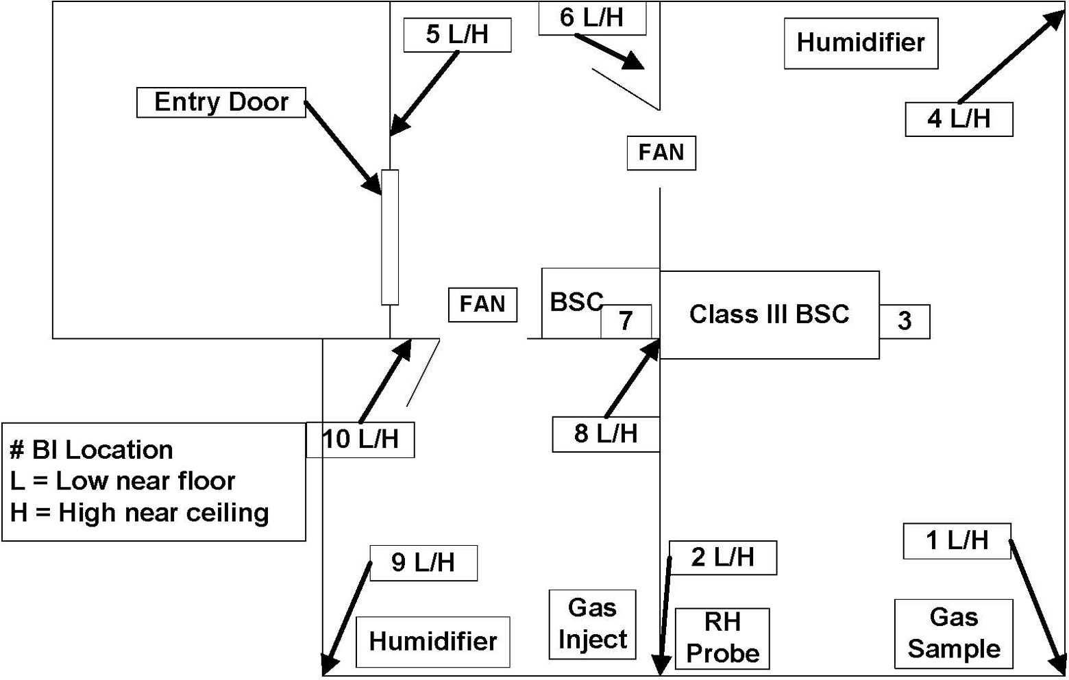
The aerobiology suite setup. This suite comprised 3 separate rooms (approximately 4077 ft3 [115 m3]). All rooms were decontaminated as 1 chamber. Chlorine dioxide gas injection was in 1 room, and the chlorine dioxide gas sample was taken from a different room. Biological indicators (BIs) were placed in various locations per the layout. Two fans were used and placed in the doorways. Two humidifiers raised the relative humidity to 65%. BSC, biosafety cabinet.
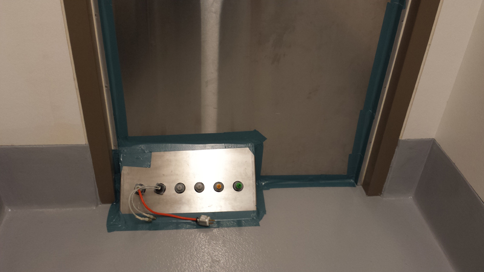
The Under-the-Door-Plate. This plate allows the chlorine dioxide gas generator connections to enter the room without any modification.
Twenty or more BIs may be used during a typical decontamination. A minimum of 4 BIs are placed in each room. For this setup, a total of 18 BIs were used. BIs were typically placed in pairs, with one being placed near the floor and the other near the ceiling. One BI was placed in the Class II, type A2 BSC. When the Class III glove box was being decontaminated with the room, the gull wing door to the Class III glove box was opened, and ≥4 BIs (depending on the amount of equipment) were placed into the glove box. In this scenario, the Class III glove box was not included.
During the testing phase, a laptop computer (Dell Latitude) was placed inside the room. This laptop computer was moved from room to room to expose it to multiple runs to test the material compatibility of CD gas. The exterior of the Class III glove box was also carefully checked for any indications of corrosion (pitting, rust spots, etc).
Finally, the HVAC to the room was blocked off by closing the bioseal dampers. The door between the anteroom and the procedure room was sealed with duct tape (see above). The Under-the-Door-Plate located at the bottom of the sealed door was also sealed with duct tape. All connections from the contaminated room were connected to one side of the Under-the-Door-Plate, and connections from the Minidox were made to the other side (Figure 2). After the door was sealed and the HVAC blocked off, a standard cycle of 1 mg/L of CD for 2 hours of exposure or 720 ppm-hours was run.
Upon completion of the gassing event, the bioseal dampers were opened, and the room was allowed to vent. Once the gas dissipated (verified by PortaSens II), the BIs were collected and taken to another room for processing. The BIs were aseptically removed from the Tyvek pouches inside a BSC and placed into growth media. Media tubes were then placed into a 56ºF incubator. BIs were checked for growth at 24, 48, and 72 hours and with a final read at 7 days.
As seen in the aerobiology cycle data chart (Figure 3), the process started with the room RH increasing from the starting value of 30% to 40% up to the required 65%. This value was maintained until the completion of the run. Once the room achieved the required 65% humidity, the CD gas was injected into the room. This continued until the room achieved the required 1 mg/L.
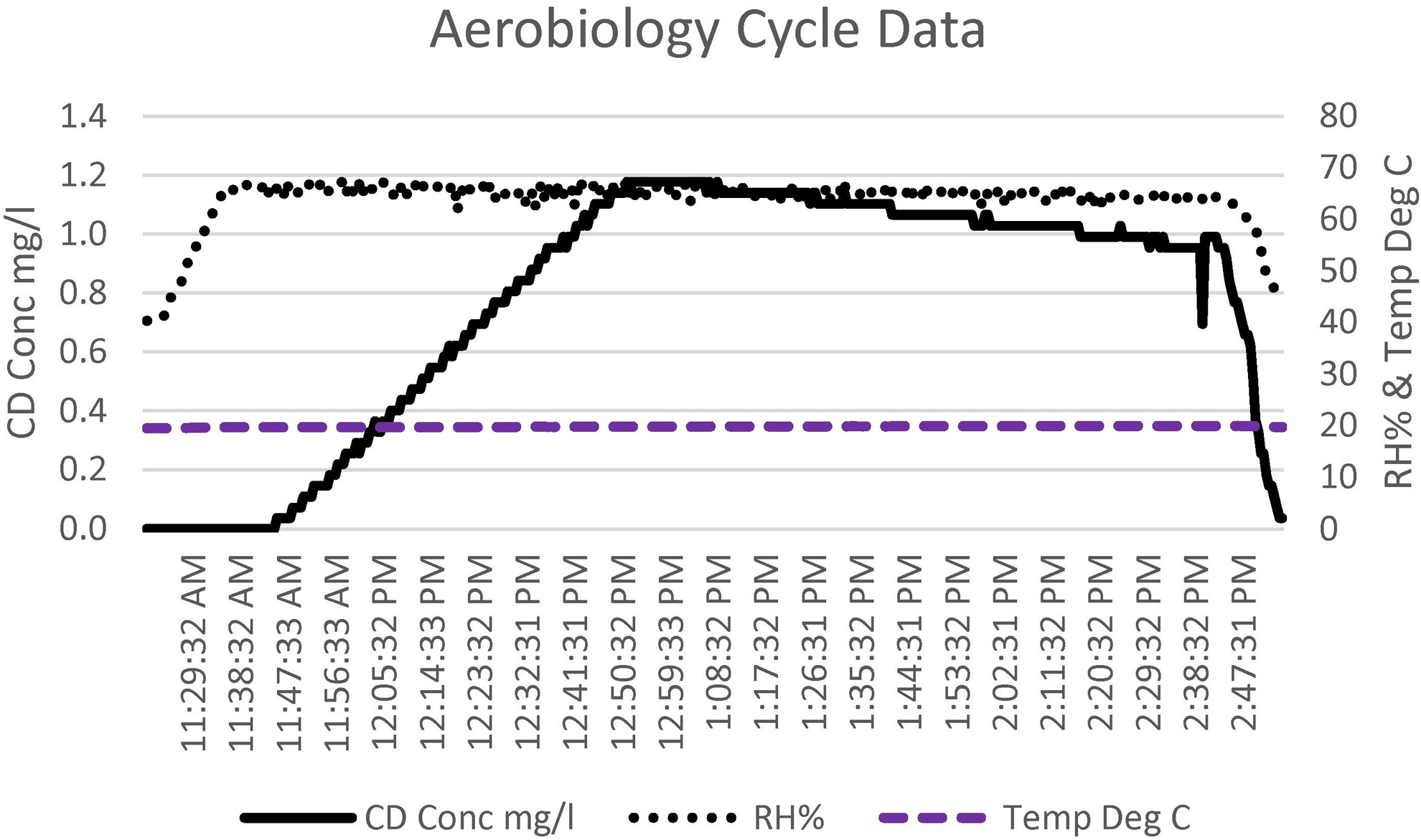
The chlorine dioxide (CD) gas concentration, relative humidity (RH), and temperature cycle data for the aerobiology suite. The total cycle time was 3.5 hours.
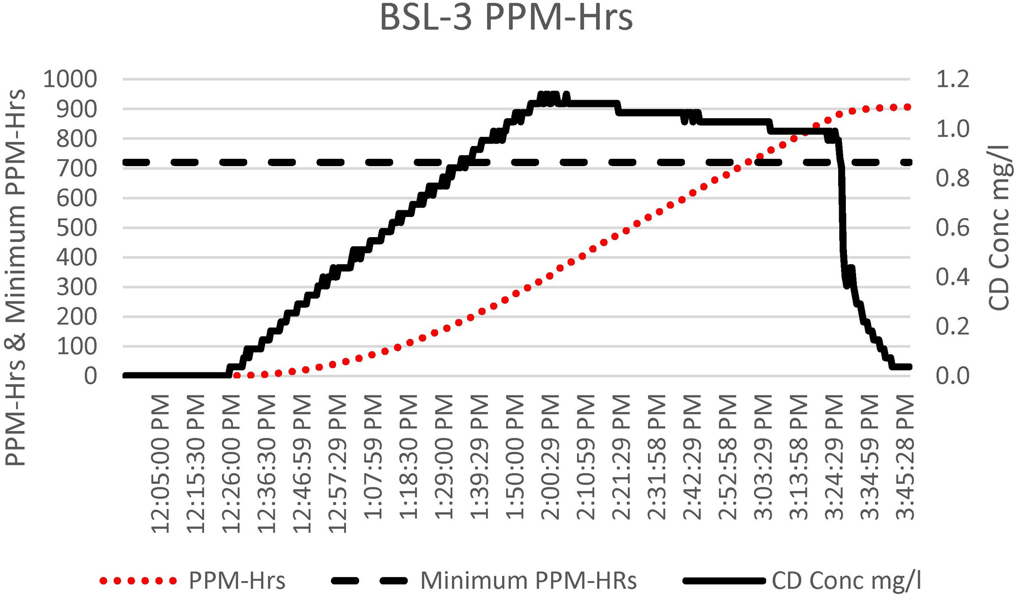
This value was maintained with the Minidox injecting more gas as needed, until the dosage of 720 ppm-hours was met or exceeded (Figure 4). The total cycle time for this chamber was <3.5 hours from the start of the cycle until CD gas was aerated down to the safe level of 0.1 ppm, which is safe for user entry.
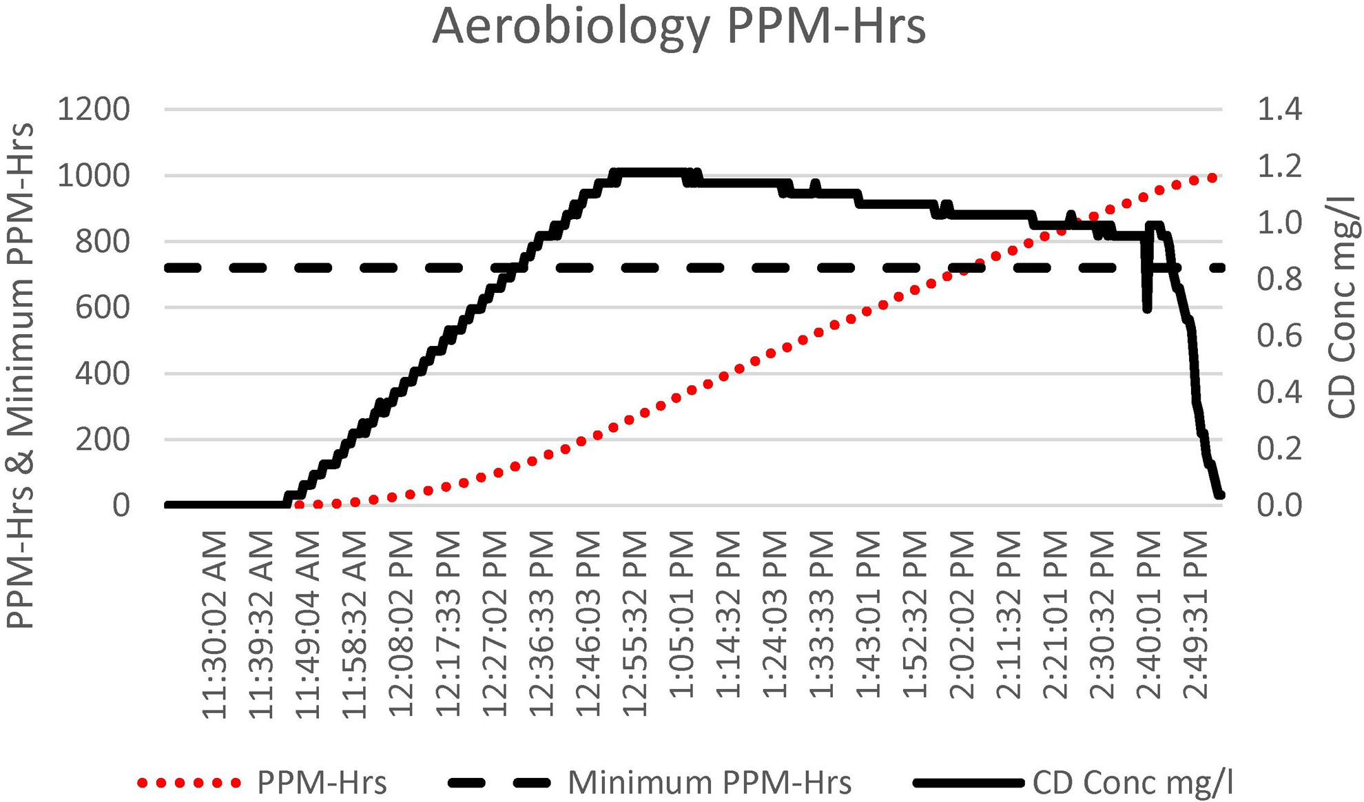
The chlorine dioxide (CD) gas ppm-hours (ppm-hrs) accumulation, ppm-hrs minimum requirement (720 ppm-hrs), and CD gas concentration cycle data for the aerobiology suite. The total cycle time was 3.5 hours.
Results
As seen by the cycle data, this run was successful on the basis of the information recorded by the Minidox. Furthermore, no growth was seen in any of the BIs placed throughout the room. The untreated BI showed growth (Figure 5). The test computer was turned on, and it continued to work without issue. The Class III glove box was carefully checked over to see if any adverse effects from the gassing were apparent. No indication of corrosion was found.
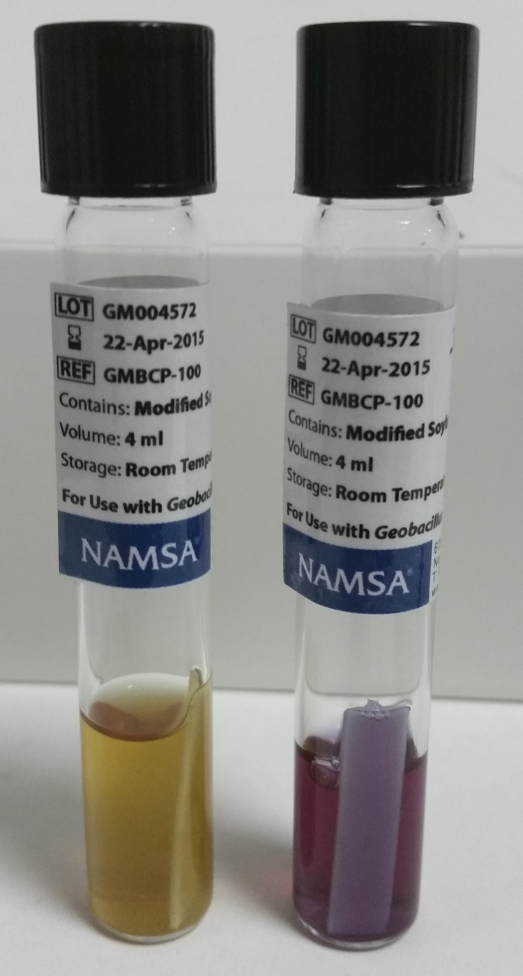
The incubation media tubes. The light tube is yellow (left) and shows growth, and the dark tube is purple (right) and shows no growth.
Gassing Event in the BSL-3 Laboratory
The room is basically shaped like a large rectangle, with the gas inject line placed in the back left corner of the room (Figure 6). The line was run across the room and under the main entry door so that it could be connected to the Under-the-Door-Plate. The sample line and RH probe were placed into the attached autoclave room (1202B on BSL-3 room setup image). Both lines were run into the main room and under the main entry door for connection to the Under-the-Door-Plate. One fan and 1 humidifier were placed in the back right corner of the room with a second set placed in the front left corner of the room.
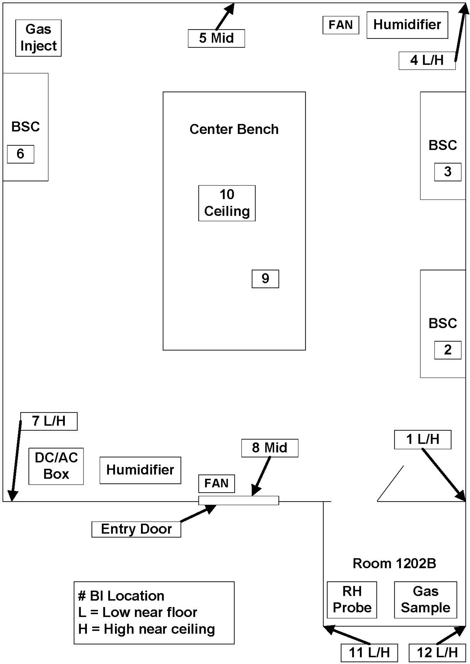
The biosafety level 3 room setup. This is one large room with a small autoclave room (approximately 5770 ft3 [163 m3]). Chlorine dioxide gas injection was in one corner of the room, and the gas sample was taken from the opposite corner. Biological indicators (BIs) were placed in various locations per the layout. Some BIs were place inside the biosafety cabinets (BSCs) to verify their decontamination at the same time as the room. Two fans and 2 humidifiers were used.
Twenty or more BIs may be used during a typical decontamination, depending on additional equipment in the room (Figure 6). For this setup, a total of 17 BIs were used. BIs were typically placed in pairs, with one being placed near the floor and the other near the ceiling. One BI was placed in each Class II, type A2 BSC, and 1 was placed in the Class II, type B1 BSC. BIs were placed at the back of the work surface. During the testing phase, the same laptop computer (Dell Latitude) that was used in the aerobiology suite tests was placed inside the BSL-3 laboratory. This same laptop computer was used to test the material compatibility of CD gas with repeated exposures. Stainless-steel surfaces such as BSC workspaces, portable carts, steel chemical storage cabinets, and the exterior surfaces of equipment were also monitored for any indication of corrosion due to gassing.
Finally, the HVAC to the room was blocked off by closing the bioseal dampers. The door between the anteroom and the main entry room door was sealed with duct tape (Figure 7). The Under-the-Door-Plate located at the bottom of the sealed door was also sealed with duct tape. All connections from the BSL-3 laboratory were connected to one side of the Under-the-Door-Plate, and connections from the Minidox were made to the other side. After the door was sealed and the HVAC blocked off, a standard cycle of 1 mg/L of CD for 2 hours of exposure or 720 ppm-hours was run.
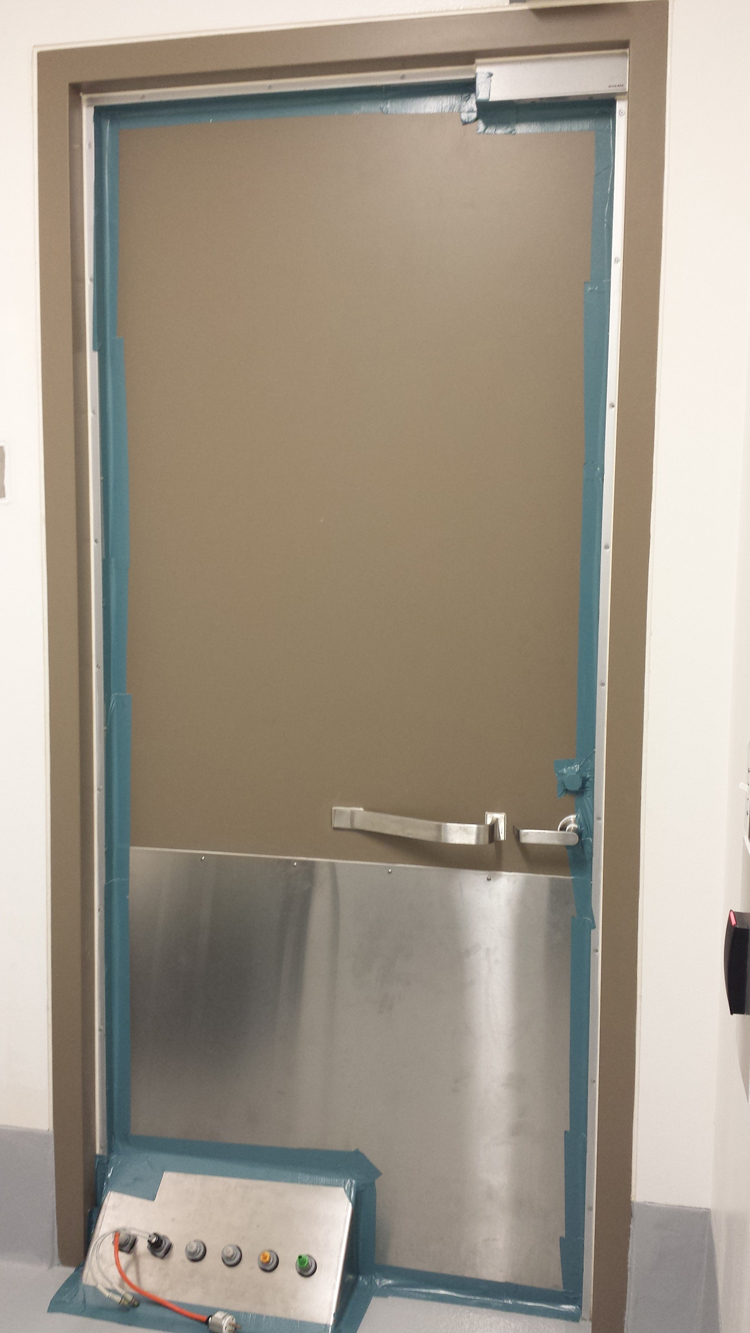
The door sealed and the Under-the-Door-Plate. This plate allows the chlorine dioxide gas generator connections to enter the room without any modification.
Upon completion of the gassing event, the bioseal dampers were opened, and the room was allowed to vent. Once the gas had dissipated (verified by PortaSens II), the BIs were collected and taken to another room for processing. The BIs were aseptically removed from the Tyvek pouches inside a BSC and placed into growth media. Media tubes were then placed into a 56ºF incubator. BIs were checked for growth at 24, 48, and 72 hours and a final read at 7 days.
As seen in the BSL-3 cycle data chart (Figure 8), the process started the same way that it did with the aerobiology suite. The room RH was increased from the starting value of 30% to 40%, up to the required 65%. This value was maintained until the completion of the run. Once the room had achieved the required 65% humidity, the CD gas was then injected into the room. The standard concentration for rooms is 1 mg/L. This value was maintained with the Minidox injecting more gas as needed, until the dosage of 720 ppm-hours was met or exceeded (Figure 9). The total cycle time for this chamber was <4 hours from the start of the cycle until CD gas was aerated down to the safe level of 0.1 ppm.
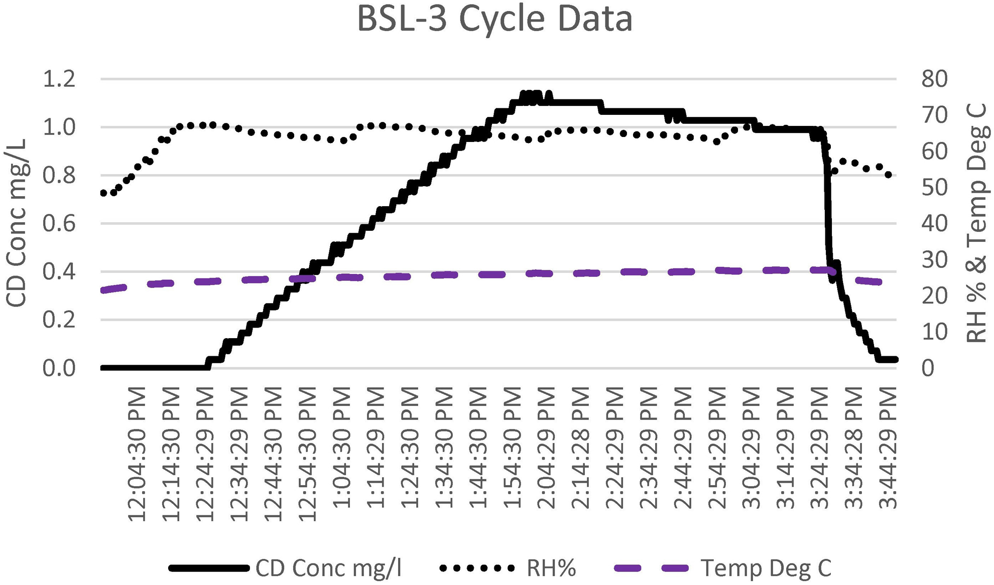
The chlorine dioxide (CD) gas concentration, relative humidity (RH), and temperature cycle data for the biosafety level 3 (BSL-3) room. The total cycle time was 4 hours.
The chlorine dioxide (CD) gas ppm-hours (ppm-hrs) accumulation, ppm-hrs minimum requirement (720 ppm-hrs), and CD gas concentration cycle data for the biosafety level 3 (BSL-3) room. The total cycle time was 4 hours.
Results
As seen by the cycle data, this run was successful on the basis of the information recorded by the Minidox. Furthermore, no growth was seen in any of the BIs placed throughout the room. The untreated BI showed growth. The test computer was turned on, and it continued to work without issue. BSC work surfaces and small stainless-steel portable carts were carefully checked to see if any pitting or rust spots were seen. The exterior surfaces of the equipment and storage cabinets were observed for similar damage. No evidence of corrosion was seen on any observed surface.
Gassing Event in the Class III BSC
The Class III BSC can be decontaminated as part of the room (by opening the gull wing door), or it can be decontaminated on its own through use of the built-in connectors (Figure 10). The components needed are RH probe, mix box (which contains a humidity generator), blower motor, DC/AC controller, pressure relief scrubber, and the Minidox. In the past, external room fans were placed inside the BSC, but these took up too much room. Therefore, the BSC was modified by placing a total of 2 small high-velocity fans in opposite corners of the BSC (Figure 11).
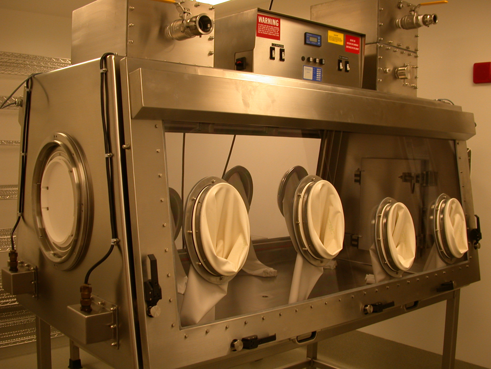
The Class III biosafety cabinet with alpha/beta port.
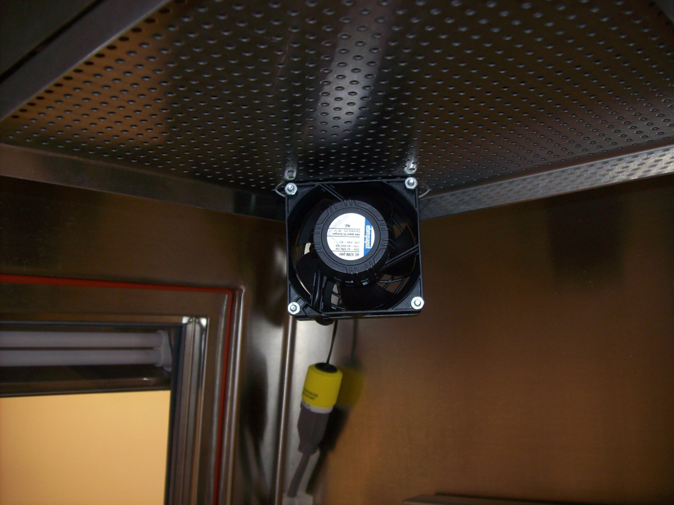
The fan placement and size inside the Class III biosafety cabinet.
Once all-the-above listed parts were connected, they made a complete circuit (Figure 12), providing gas injection and sampling, RH injection and sampling, and off-gassing when needed. All of this was connected to the Minidox for needed recording. A 1.5-in diameter hose was used to complete a circuit between a blower module and the Class III glove box. Humidified air and CD gas passed from the blower module into the supply connector port of the Class III cabinet. Upon entering the chamber, the air was dispersed evenly throughout by the 2 small fans mounted in the corners of the glove box, before exiting the exhaust connector port and completing the circuit back to the blower module.
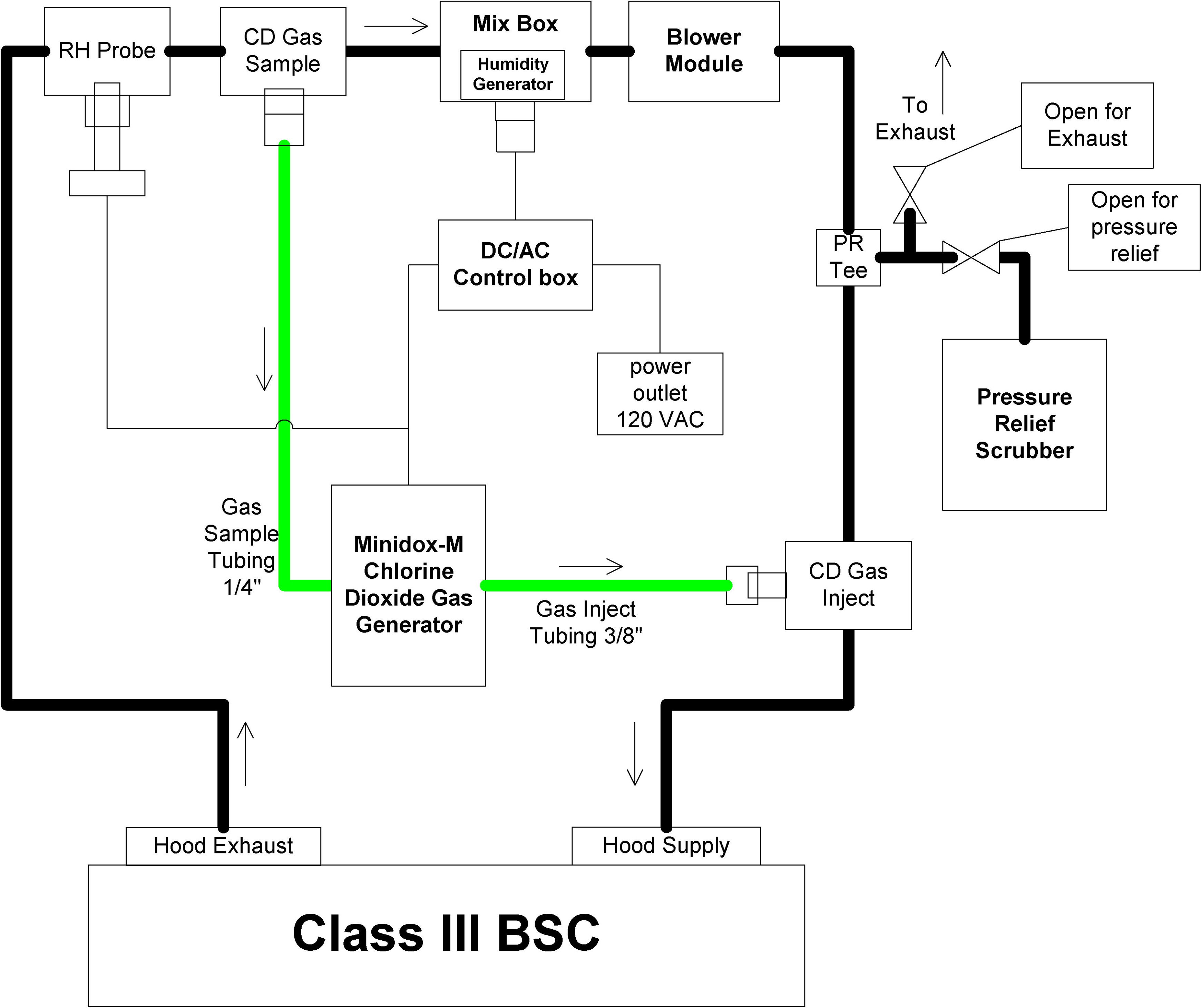
The chlorine dioxide (CD) gas generator connections to the Class III biosafety cabinet through the SCT System. The SCT System connects to the Class III biosafety cabinet through 1.5-in hoses with cam-lock fittings. The chlorine dioxide gas generator connects to the SCT System through the relative humidity (RH) probe tee, gas sample tee, gas inject tee, and pressure relief (PR) tee. The humidity generator is located inside the mix box, and the blower module circulates the air through the system.
The Minidox controlled the humidity through feedback from the RH probe mounted in the exhaust hose. The information was fed from the RH probe to the Minidox, which then activated the DC/AC control box, turning the humidifier (located in the mix box) on and off as needed. The CD gas concentration was monitored via a gas sample port. This hose was connected to the Minidox, which then, on the basis of real-time readings, activated the gas injection system as needed. The gas was injected into the main supply hose via an injection port.
Overpressurization of the system was controlled through a pressure relief scrubber connected via a T-connector to the main supply hose. This system has ball valves that can be opened and closed to bleed off any excess pressure. The scrubber removes any CD gas during this process.
For testing purposes, the same laptop computer was placed inside the Class III glove box. Stainless-steel aerosolization equipment (CH Technologies, Westwood, New Jersey) left inside the glove box was carefully checked for any signs of corrosion. This equipment is used to aerosolize bacteria, viruses, or other protein compounds. Having the inner surfaces of these components free of any imperfections is critical since any imperfections would interfere with the aerosolization process. Thus, not having the CD gas cause any pitting or rusting is important.
A standard cycle of 5 mg/L for 30 minutes of exposure is often used for Class III BSCs. However, due to the nature of this work, the cycle time was extended to 45 to 60 minutes. The number of BIs used in the Class III cabinet varies depending on the amount of equipment being used at the time. However, as a general rule, a minimum of 10 BIs are used.
For this cycle, the dedicated exhaust fan was turned off, and all bioseal dampers leading to the Class III cabinet were closed. The circuit was then allowed to run with humidity being injected until the RH of 65% was reached (Figure 13). While the BSC tends to have a higher humidity at the start, a 30-minute conditioning phase is still allotted. The longer conditioning phase is due to the shortened exposure as compared with room cycles. Once the conditioning phase was over, CD gas was injected with humidity being added only to maintain the RH reading. Once the 5 mg/L of CD concentration had been reached, the system continued to circulate for the allotted time (45-60 minutes; Figure 14). While ppm-hours are recorded, for such a small space, the Minidox cycle was set to run for a predetermined amount of exposure time.
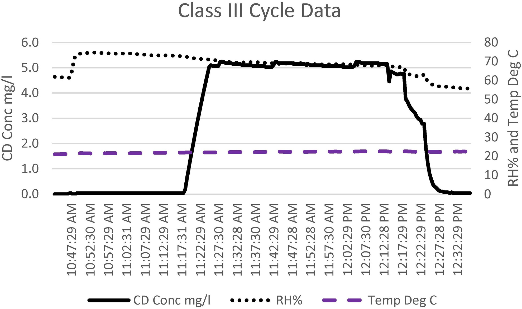
The chlorine dioxide (CD) gas concentration, relative humidity (RH), and temperature cycle data for the Class III biosafety cabinet. The total cycle time was 1.75 hours.
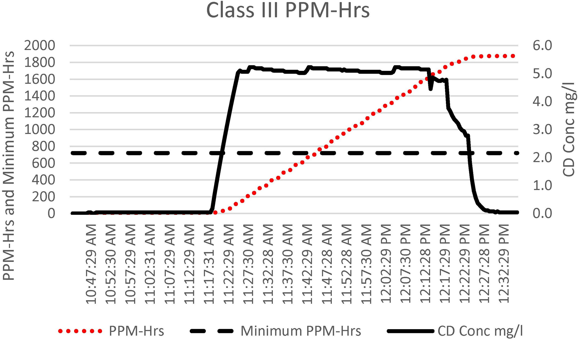
The chlorine dioxide (CD) gas ppm-hours (ppm-hrs) accumulation, ppm-hrs minimum requirement (720 ppm-hrs), and CD gas concentration cycle data for the Class III biosafety cabinet. The total cycle time was 1.75 hours.
At the completion of exposure, the bioseal dampers were opened with the exhaust fan turned back on, and the unit was allowed to vent. The total cycle time for this chamber was <1.75 hours from the start of the cycle until CD gas was aerated down to the safe level of 0.1 ppm.
Results
As seen by the cycle data, this run was successful. No growth was seen in any of the BIs placed throughout the chamber. The untreated BI showed growth. Additionally, even with the higher CD gas concentration and extended time, the test laptop computer functioned without issue. No damage or adverse conditions were noted in the aerosolization equipment. All components continue to remain free of any imperfections.
Discussion
Installation, startup, and training were simple. The CD gas generator machine is self-explanatory and simple to operate after training. The cycles provided by the manufacturer worked with no changes. These were the normal cycles used by other facilities. However, for the Class III BSC, the time was extended from the standard 30 minutes to 45 to 60 minutes due to the nature of the work being conducted. The basic cycle for CD consists of 5 steps: precondition, condition, charge, exposure, and aeration. The process begins with precondition, which raises the level of humidity to 65%. Humidity or moisture is critical for all spore log reductions, no matter which agent is used (formaldehyde, CD gas, or VPHP).14 –17 This amount of RH is often confused as being a high level of RH and requiring tight controls. However, this level is easily achieved and controlled through small, commercially available fabric steamers. The Minidox control system measures and maintains the RH to the set point of 65%.
Even distribution of vapors is difficult; however, with a set point of 65%, the minimum RH levels are easily reached in all areas. If the RH is a little higher or lower around the room, it is acceptable since the RH requirements for CD gas are not tight. Once the RH reaches the target, it is allowed to sit for 10 minutes in rooms (30 minutes in a Class III glove box). This step is the conditioning step. Once the conditioning step is completed, the charge step is next. In this step, the CD gas is injected to reach the target set point of 1 mg/L (362 ppm) or 5 mg/L for Class III BSCs. The Minidox control system measures the concentration to ensure that the target concentration is reached each time, thereby guaranteeing that the same cycle is achieved regardless of what is in the room. When the concentration is verified to be at 1 mg/L (or 5 mg/L for BSCs), the cycle progresses to the exposure step. In this step, the CD gas concentration is monitored and maintained. This step continues until the dosage or concentration time (ppm-hours or specified time) exceeds 720 ppm-hours (or the set time interval). When this value is reached, aeration is started. In this step, fresh air is brought in, and the gas is removed by the house exhaust system. Typical aeration requires 12 to 15 air exchanges to remove the gas to safe levels (0.1 ppm) for entry into the room. This time is typically 45 minutes for rooms. Aeration time for this project was on average between 45 and 60 minutes, which matched the calculated and published aeration times.18 –21
CD gas is an oxidizer, but when it is produced with a dry gas and used as a gas, it is not corrosive as gases in solutions typically are. Solutions of CD gas are typically corrosive due to the acids and sodium chlorite involved. Since CD gas is an oxidizer, tests were conducted by repeatedly exposing a laptop computer, monitoring various work surfaces, and observing critical pieces of equipment for any signs of corrosion during every run for many runs. For this, a basic laptop computer was moved from room to room and chamber to chamber for each exposure. Although it was exposed to >35 cycles of CD gas, the laptop continued to function. Additionally, various work surfaces (BSC workspace) and several pieces of equipment (storage cabinets, centrifuges, etc) were monitored via visual inspection for signs of corrosion. No work surfaces or equipment were found to have any damage, and they continued to be corrosion free. A particularly sensitive piece of equipment—CH Technologies’ nose-only inhalation system used in the aerosolization of bacteria and viruses—was carefully scrutinized for any adverse signs (pitting, rust spots, etc) during repeated exposure to CD gas while decontaminating the Class III glove box. Despite the higher concentration of CD gas compared with that of rooms (5 vs 1 mg/L), extended decontamination times, and in excess of 42 decontamination cycles, no signs of damage were seen on any surface of the aerosolization equipment. This is especially important, as any rusting or pitting of the surfaces could have negatively affected the calibration and operation of the equipment—if severe enough, even rendering it inoperative. This equipment also continued to be corrosion free.
BIs were placed in various locations in each room and throughout the Class III glove box. They were placed in challenging locations, and all were 106 BIs. All BIs were killed. Using 106 spore strips engendered confidence that any organisms used in the facility would be killed. Two BIs were placed at each location. This was done following the process that Luftman et al 22 used to validate CD gas in BSCs. The reason for following this validation process is that in a 2-BI experiment—one coming back negative and the other positive—the probability is 95% that a 5.7-log reduction with 6-log spore strips will occur. 22
Yearly at this facility and in conjunction with its recommissioning, an outside firm decontaminates the whole facility; this includes all vivarium and BSL-3 rooms, hallways, equipment areas, and storage rooms. When room decontaminations are performed by in-house staff during routine decontaminations, the hallways and some equipment areas are not typically done. With performance of a yearly overall decontamination, we are confident that this facility is safe and clean for its recommissioning process and for any maintenance that is needed.
Conclusion
CD gas met the need to provide a complete decontamination of all surfaces within the containment areas and inside the Class III BSC. BIs were killed repeatedly, and there were no issues of corrosion.
Footnotes
Declaration of Conflicting Interests
The author(s) declared the following potential conflicts of interest with respect to the research, authorship, and/or publication of this article: Mr. Mark Czarneski is an employee of ClorDiSys Solutions, Inc., USA. The other author(s) declare no conflicts or financial interest in any product or service mentioned in the article, including grants, equipment, medications, employment, gifts, and honoraria.
Funding
The author(s) received no financial support for the research, authorship, and/or publication of this article.