
Abstract
Purpose:
To assess the quality of cone beam computed tomography images obtained by a robotic arm-based and image-guided small animal conformal radiation therapy device.
Method and Materials:
The small animal conformal radiation therapy device is equipped with a 40 to 225 kV X-ray tube mounted on a custom made gantry, a 1024 × 1024 pixels flat panel detector (200 μm resolution), a programmable 6 degrees of freedom robot for cone beam computed tomography imaging and conformal delivery of radiation doses. A series of 2-dimensional radiographic projection images were recorded in cone beam mode by placing and rotating microcomputed tomography phantoms on the “palm’ of the robotic arm. Reconstructed images were studied for image quality (spatial resolution, image uniformity, computed tomography number linearity, voxel noise, and artifacts).
Results:
Geometric accuracy was measured to be 2% corresponding to 0.7 mm accuracy on a Shelley microcomputed tomography QA phantom. Qualitative resolution of reconstructed axial computed tomography slices using the resolution coils was within 200 μm. Quantitative spatial resolution was found to be 3.16 lp/mm. Uniformity of the system was measured within 34 Hounsfield unit on a QRM microcomputed tomography water phantom. Computed tomography numbers measured using the linearity plate were linear with material density (R 2 > 0.995). Cone beam computed tomography images of the QRM multidisk phantom had minimal artifacts.
Conclusion:
Results showed that the small animal conformal radiation therapy device is capable of producing high-quality cone beam computed tomography images for precise and conformal small animal dose delivery. With its high-caliber imaging capabilities, the small animal conformal radiation therapy device is a powerful tool for small animal research.
Introduction
In recent years, the advances in imaging and computing technology have played a crucial role in the development of high-resolution imaging system suitable for both clinical and small animal studies. The development and commissioning of the microcomputed tomography (microCT) system for small animals that can provide high-resolution anatomic information of the order of submicron resolution have been reported. 1 –3 Microcomputed tomography has become a valuable tool for radiobiological studies involving new molecular, genetic, and proteomic techniques that cannot be tested directly in the clinic without first establishing feasibility and toxicity evaluation in small animal (mice, rats, and rabbits) studies. 4
With the rapidly developing computing technology and a high-resolution X-ray flat panel detector, animals can be imaged in cone beam computed tomography (CBCT) geometry in a very short time with less radiation exposure than microCT systems. 5 To scale down clinical measurements in a small animal model, there is a need for a high-resolution small animal imaging and a conformal irradiator that incorporates a bench top system and facilitates the understanding of anatomic and temporal information. We have developed a prototype small animal conformal radiation therapy device (SACRTD), which is a robotic system, that is capable of imaging and delivering conformal radiation.
In this article, a general overview and performance of SACRTD’s CBCT imaging capability is presented. The article discusses the imaging tests and the corresponding QA phantoms in detail, while highlighting the potential application in small animal studies, and mentions a few limitations. Accuracy and detectability of the imaging system was first established with standard phantom measurements followed by mouse/rat imaging.
Methods and Materials
Background and System Description
The SACRTD system consists of a dual focus GE Seifert Isovolt Titan 225M2 X-ray tube (Seifert, Lewistown, Pennsylvania) mounted on a custom made “gantry” (as shown in Figure 1), which has a special collimating assembly that allows field sizes down to 0.5 mm diameter at the isocenter (source to axis distance, SAD = 32.5 cm). The resolution of the image primarily depends on the X-ray focal spot size. The small focus (0.4 mm) is generally used for high-resolution imaging (60-120 kVp, 640 W) and the large focus (3.0 mm) that can deliver a larger dose output is used for conformal radiation therapy at higher energies (150-225 kVp, 3000 W). The SACRTD has a field of view (FOV) up to 20 × 20 cm2 at the isocenter, a 6-dimensional robot and a 1024 × 1024 detector at 200 μm resolution. 6 The SACRTD is kept inside a 1.8 × 1.8 × 1.8 m3 enclosure whose walls are shielded with a 2.5 cm equivalent lead blankets designed to meet the National Council on Radiation Protection and Measurements (NCRP) report-# 49 requirements. 7 The Adept Viper S650 (Adept Inc, Fremont, California), is a 6-axis flexible and high-precision robot with 6 degrees of freedom. 8 The robotic arms can translate or rotate about the 3 cardinal axes, giving all possible orientations in a nearly spherical working space. The specially designed plexiglass platform or “palm” is mounted at the end of robot’s arm, which is used as the animal immobilization apparatus for imaging and therapy. During CBCT acquisition, the X-ray tube and detector stays stationary while the robotic arm rotates the small animal around the vertical axis.

Cone beam CT acquisition configuration of SACRTD with static gantry and a micro CT imaging phantom rotating on the palm of the robotic arm. CT indicates computed tomography; SACRTD, small animal conformal radiation therapy device.
Conformal Irradiation Capability
The X-ray tube is mounted on a custom made “gantry,” which can rotate up to 120° about isocenter. The system uses a variable aperture collimating assembly that allows field sizes between 0.5 mm diameter and 20 mm × 20 mm at the isocenter (SAD = 32.5 cm). For more details, the readers can refer to Sharma et al 9
Cone Beam CT System
Digital X-ray images are acquired using the Perkin Elmer XRD 0820 CN3 Digital X-Ray flat panel detector made up of amorphous silicon (a-Si)-based photodiode array which converts detected X-rays into light using CsI:TI scintillator. 10 The data acquired by the a-Si/CsI flat panel system are digitized in 16 bits to achieve high dynamic range and contrast. With a spatial resolution of 200 μm, an image size of 1024 × 1024 pixels, and a frame rate of 7.5 Hz, the detector is designed to fulfill the high-resolution imaging requirements of small animals.
Image acquisition configuration consists of a horizontal gantry directing X-rays at the target using the small focal spot of 0.4 mm. The flat panel detector with an area of 20.48 cm2 is at 23 cm from the radiation/gantry isocenter and 56 cm away from the X-ray source, thus producing a 1.7 image magnification factor. The animal to be imaged is immobilized on the “palm” of the robotic arm, which can position and rotate the target along the line of detector and X-ray source for imaging within ±0.2 mm positional accuracy and ±0.2° angular precision along the 3 cardinal directions. Images can be acquired in either continuous mode or stop-and-capture mode, as explained in the rat heart irradiation study by Sharma et al. 9 An in-house Visual BASIC-based software tool has been developed that controls the robot motion, the X-ray trigger activation and data acquisition by the imager. Image quality parameters were studied using an in-house implemented Feldkamp-Davis-Kress filtered back projection algorithm in CBCT reconstruction using MATLAB (Mathworks, Massachusetts). 11
Computed Tomography Imaging System Performance Evaluation
In order to evaluate imaging characteristics of the system, several microCT QA phantoms were scanned in the cone beam mode to access a variety of image quality parameters. Images were acquired over a range of kV (60-120 kVp) and mA values (1-5 mA). The images were studied for qualitative and quantitative features including geometric accuracy, image uniformity, spatial resolution, CT number, linearity, image noise, and artifacts.
Shelley microCT QA phantom
The Shelley microCT QA phantom (model vmCT610, Shelley Medical Imaging Technology, Ontario, Canada) enclosed in an 84 mm long and 70 mm diameter cylindrical housing was used to evaluate CT number, linearity, uniformity, geometric accuracy, slanted edge, resolution, and CT number. 12
Geometric accuracy
The true in-plane voxel size measurement in the reconstructed axial CT image was performed by using the geometric accuracy plate which has five 0.28 mm diameter tungsten carbide beads. Four beads are located 35 mm apart to form a square and the fifth bead is located at the center of the plate at a distance of 24.75 mm from other beads. The distances between the bead in the centroid to that of its neighboring bead were measured and compared against ground truth.
Resolution plate
The qualitative measurement of the spatial resolution of the system was visually observed with the resolution plate. The plate consists of 4 spiral coils of alternating aluminum and Mylar sheets rolled tightly in a 6.6 mm long tube with 16.4 mm outer diameter of the assembly. The tube contains 150, 200, 300, and 500 μm thick coils corresponding to 3.3, 2.5, 1.67, and 1 lp/mm, respectively.
Slanted edge plate
The modulation transfer function (MTF) of the system is measured using a slanted edge plate with a plastic and air boundary at an angle of 5° relative to the CT scanner image matrix. A series of 10 reconstructed slices of the slanted plate were averaged to generate an image with reduced noise. Edge spread function (ESF) defined as the 2-dimensional Fourier transform of an edge along a straight line orthogonal to the edge was measured on the averaged image. The Fourier transform of line spread function obtained from the derivative of ESF gives pre-sampled MTF of the detector.
Computed tomography number evaluation
Measurement of the CT Hounsfield unit (HU) number was performed from a plate embedded with 8 different materials, commonly encountered in animal imaging including cortical bone equivalent tissue (SB3), a silicone-based vascular contrast agent compound (Microfil), polytetrafluoroethylene (Teflon), high-density polyethylene, fat-mimicking epoxy resin, muscle-mimicking epoxy resin, polymethyl methacrylate (PMMA) plastic, and water-equivalent epoxy resin. Each material sample is 3 mm in thickness and placed around a concentric circle of 44 mm diameter. A 3-mm diameter air hole present at the center of the plate was used to evaluate the air signal within the object.
Computed tomography linearity plate
The CT number linearity was measured using a plate that consists of varying iodine concentrations, mimicking contrasts used in animal experiments. The concentration of the 6 vials containing iodine solutions prepared from nonionic contrast material are 0.9375, 1.875, 3.75, 7.5, 15, and 30 mg/mL. Two additional vials of water and air are included.
Water-filled phantom
The homogeneity/uniformity and noise of the reconstructed image were also investigated with cylindrical phantom filled with water (Micro-CT water phantom, Quality Assurance in Radiology and Medicine, Germany). 13
The QRM-MicroCT-Water Phantom is a hollow cylinder of 32 mm diameter, 40 mm length, and 0.2 to 0.5 mm wall thickness filled with distilled water. It offers an intake/outlet screw in a convex closure head such that it can be used in a rotating gantry or in the upright position. A small cavity in the upper part of the phantom detains air bubbles if used in a horizontal position. The phantom is made up of a low density (1.0 g/cm3) stable transparent plastic. The transparent wall allows the detection of air bubble easily.
Wire phantom
The wire phantom (Micro-CT wire phantom QRM, Germany) is a tool to assess in-plane spatial resolution of a Micro-CT system. 14 The QRM MicroCT Wire Phantom consists of a cylinder containing 2 wires in air aligned parallel to the phantom axis of rotation. One of the wires is located slightly off-center, and the second one lies away from the center in order to allow the image quality estimation in the periphery. The point spread function and MTF can also be estimated.
Bar phantom
The QRM-MicroCT-MultiDisk phantom is a short cylinder with 20 mm diameter and 48.5 mm height. 15 It consists of a stack of 8 alternating high-density and low-density circular disks of 3 mm thickness each. The phantom was terminated with 10 mm of PMMA glass on either side. The MicroCT Multi Disk phantom is used to test CBCT acquisition artifacts from microCT scanners and reconstruction algorithms. The phantom was scanned in cone beam geometry in steps of 1° resulting in 360 projections.
Results
The CBCT scans were reconstructed by using raw projection images as input to the filtered back projection algorithm. The reconstructed images were median filtered, ring artifact corrected, 16 and metal artifact reduced by adaptive filtering of raw data. 17 The reconstruction time for an image of size 1024 × 1024 pixels with 200 μm resolution was ∼20 slices/minute. The resulting reconstructed voxel size was 0.146 × 0.146 × 0.146 mm3 along the 3 axes for an object placed at the isocenter.
Geometric Accuracy
The distance measurements between 5 beads at known distances in a Shelley microCT QA phantom was within standard deviation (SD) ≤0.5% of the manufacturer specified distances. The center bead is at a distance of 24.75 mm from the 4 other beads positioned in 4 corners at 35 mm from one another, as shown in Figure 2.

SACRTD reconstructed image of the Shelley microCT QA phantom showing geometric distance between the (A) 4 corner beads from the center bead and (B) 4 corner beads from one another. The measurements were within 2% of the manufacturer specified distances of 24.75 and 35 mm, respectively. CT indicates computed tomography; SACRTD, small animal conformal radiation therapy device.
Spatial Resolution
The visual evaluation of reconstructed axial CT images of the resolution coil plate in the Shelley microCT phantom can resolve the 200 μm thick coil (corresponding to 2.5 lp/mm) clearly, but not the 150 μm thick coil (3.3 lp/mm), as shown in Figure 3.

(A) SACRTD reconstructed axial image of the resolution coil plate in the Shelley microCT phantom and (B) magnified view of the smallest coil that can be resolved by naked eye (200 μm layer thick coil corresponding to 2.5 lp/mm). SACRTD indicates small animal conformal radiation therapy device.
Modulation Transfer Function
Ten reconstructed images of the air-slanted edge interface in the Shelley microCT phantom were averaged to get the edge spread and modulation function, as shown in Figure 4. Quantitative spatial resolution was assessed using the slanted edge plate and found to be 3.16 lp/mm. Modulation transfer function resolution at 50% of intensity was 0.76 and 0.72 lp/mm in raw and Gaussian smoothed data, respectively. Modulation transfer function resolution at 10% of intensity was 1.65 and 1.48 lp/mm in raw and Gaussian smoothed data, respectively.

A, Axial reconstructed image of the Shelley microCT phantom with slant edge showing region of interface with air. B, ESF—raw and Gaussian smoothed as a function of distance across the edge. C, Raw and Gaussian smoothed MTF variation with spatial resolution (lp/mm). CT indicates computed tomography; ESF, edge spread function; MTF, modulation transfer function.
Computed Tomography Numbers
The mean (SD) CT numbers recorded for 8 different insert materials and air in the CT number evaluation plate in Shelley microCT phantom are listed in the Table 1. Also shown are the mean (SD) values of the CT number evaluation plate in a Shelley microCT phantom study acquired on a similar microCT system by Du et al. 18 The mean difference between the CT HU values in the 2 studies was 59 HU or 5.9%.
Mean (SD) Values of HU Values of the CT Number Plate in the Shelley microCT Phantom in Comparison With Results From Another microCT Study.
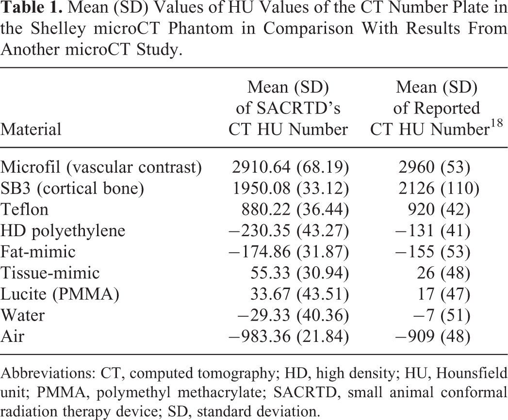
Abbreviations: CT, computed tomography; HD, high density; HU, Hounsfield unit; PMMA, polymethyl methacrylate; SACRTD, small animal conformal radiation therapy device; SD, standard deviation.
Computed Tomography Linearity
The signal intensities (HU) in the Shelley microCT phantom were determined to be linear with the different concentrations of iodine in the 8 vials with a Pearson correlation coefficient, R 2 = 0.996 (Figure 5). Du et al had reported CT number linearity with varying iodine concentrations that agree with this study to be within 4.5%. 18
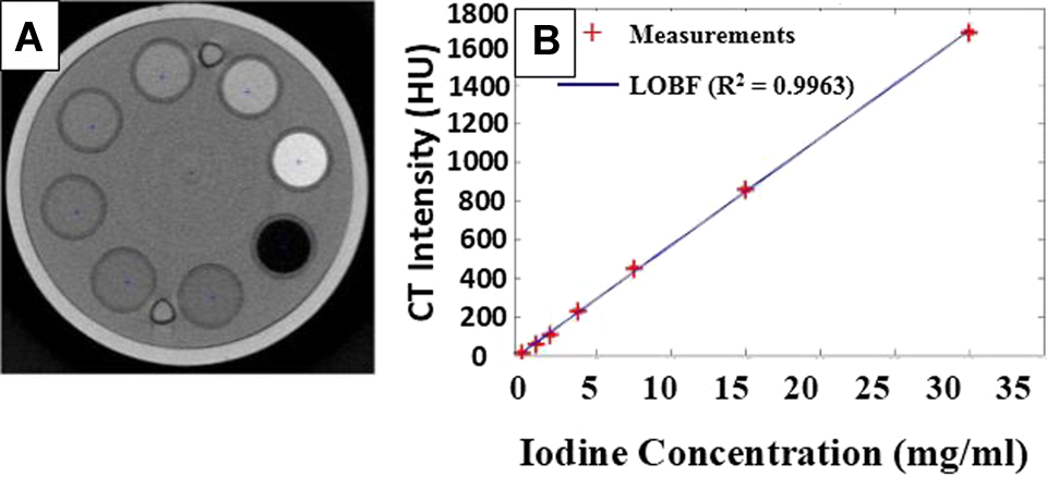
A, Reconstructed image of the Shelley microCT phantom with 8 different concentrations of iodine. B, CT number (HU) measurements and a line of best fit (LOBF) plot for different concentrations of iodine (range: 0-30 mg/ml) was linear. CT indicates computed tomography; HU, Hounsfield unit.
Ring Artifacts
The axial reconstructed CT images from the flat panel detector are often corrupted by light ring artifacts of varying intensity, as shown in Figure 6A. These ring artifacts are associated with the sensitivity of pixel elements, type of detector, detector gain, defect, or impurities in detector element, small drift in imaging condition, and so on. Ring artifacts observed in CBCT images were reduced by processing them after reconstruction using a Matlab-based median filter (Figure 6B). Detector calibration and background correction prior to image acquisition reduce but does not completely eliminate the ring artifacts.

(A) Reconstructed axial slice of the CT linearity plate in the Shelley microCT phantom with ring artifacts and (B) the corresponding median filtered image. CT indicates computed tomography. CT indicates computed tomography.
Computed Tomography Uniformity and Noise
The noise of the signal intensity was measured to be 34 HU on a QRM-microCT water-filled phantom. Radial profile of the CBCT reconstructed image of the water phantom is displayed in Figure 7. The HU values were measured on the middle slice of the QRM-microCT water phantom using 3 exposure intensities typically used in animal experiments—65 kV, 5 mA; 85 kV, 2 mA; and 105 kV, 1 mA. The HU value measurements were repeated at the center, top, right, bottom, and left positions of the reconstructed image and the results were tabulated in Table 2.
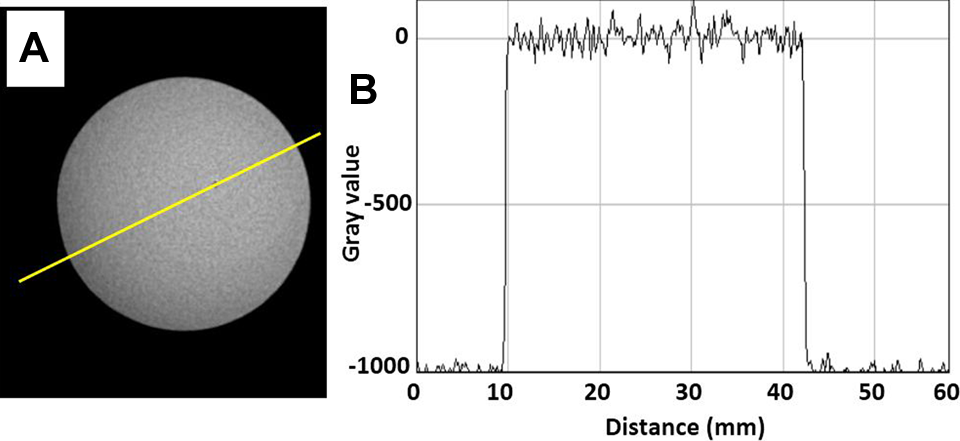
(A) An axial slice of the reconstructed QRM-micro CT water phantom with a yellow line drawn across for profile measurement and (B) the corresponding signal profile.
Mean (SD) Values of CT HU Values in 5 Different Regions of Interest in the QRM-Micro CT Water Phantom Acquired in 3 Exposure Intensities.

Abbreviations: CT, computed tomography; HU, Hounsfield unit; SD, standard deviation.
In-Plane Spatial Resolution
The QRM Micro-CT Wire Phantom used as a tool to assess in-plane spatial resolution of the CBCT system consists of 2 wires (25 μm thick) in air aligned parallel to the longitudinal axis. The visibility of the wires in a single slice in the coronal and axial plane can be verified in Figure 8 that also displays 3-dimensional reconstruction of the wire phantom.

Coronal (A), axial (B), and 3-dimensional reconstruction (C) views of the microCT wire phantom.
Imaging Artifacts
The reconstructed CBCT images of QRM microCT Multi Disk phantom acquired with ×1.7 magnification (microCT disk phantom positioned at the isocenter) was found to have no observable distortion along the longitudinal FOV of the phantom (Figure 9). In addition, the spatial resolution and noise were similar to that obtained at the periphery of the FOV of the water phantom scan. Axial, coronal, and 3D reconstructed slices of the QRM microCT Multi Disk phantom showed no distortion or artifact.

Axial, coronal, and sagittal slices of the QRM microCT Multidisk phantom with overlay of the profile along longitudinal direction and the reconstructed 3-dimensional images. CT indicates computed tomography.
Cone beam computed tomography scans of a rat were acquired using the SACRTD system. A projection image of a mouse (Figure 10) shows some of the anatomical structures that can be used for targeting and treatment planning. A representative set of reconstructed images with isotropic resolution of 0.18 mm along the 3 axes is displayed in Figure 11.
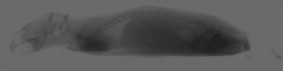
Representative image of mouse projection view before reconstruction in 3-dimensional.

The sagittal, axial, and coronal CBCT reconstructed images of a rat at a resolution of 0.18 mm × 0.18 mm × 0.18 mm in the X, Y, and Z directions. CBCT indicates cone beam computed tomography.
Discussion
There is a growing interest in developing micro-imaging and micro-irradiators that can translate the preclinical model to the clinical environment in addition to radiobiological studies. 19 With the advent of high-speed computers and high-resolution scanning techniques, sub-mm voxel size imaging systems are more commonly available including a commercially available small animal radiation research platform (SARRP) from Xstrahl Life Sciences (Camberly, United Kingdom) 20 and the Precision X-ray Inc (North Branford, Connecticut). 21 The commercial systems offer CBCT-based localization and improved targeting along with inverse planning tools, intensity modulation, and respiratory gating. The purpose of this study is to describe the imaging assessment of one such novel system developed at our institution.
This article has demonstrated extensive qualitative and quantitative techniques to assess imaging capabilities of the SACRTD system. With regard to geometric accuracy test based on the known position of beads, our recorded accuracy of 2% were comparable with manufacturer’s specification. 18
With the accurately reproducible targeting accuracy of the system and the ability to correct for any isocenter shift, end-to-end tests have revealed an isocenter displacement < 0.2 mm. 6 The target localization accuracy is comparable with any other similar system. For example, the Stanford and Princess Margaret based micro-CT systems possess an accuracy of 0.1 mm 22 and 0.2 mm, 23 respectively. The SARRP was reported to an average offset of 0.2 mm in translation and 0.2° in rotation vector in the CBCT image, 24 which coincides with the measurements of our system as well.
The resolution of the system was found to be 0.72 and 1.48 lp/mm at 50% and 10% modulation, respectively. The resolution of the detector was evaluated to be 200 μm. Our results are comparable with a MTF of 2.5 lp/mm at 10% intensity level that correspond to a resolution of 200 μm reported for a similar microCT system. 18 It is worth mentioning here that the imaging study by Du et al was performed at 80 kVp and 70 mA, while we had used 60 kVp and 5 mA.
The image noise varied with the system parameters used as expected. Our investigations show that noise of ±34 HU based on a QRM microCT water phantom was comparable with ±35 HU reported on a microCT system using a Shelley microCT water phantom. 18
The linearity of the CT number in the reconstructed images was found to remain within an accuracy of R2 > 0.996. Our results on CT number linearity with varying iodine concentration agree closely with the study by Du et al. 18
The SACRTD system has been in active use for research in both radiation therapy and diagnostic imaging capabilities of subcutaneous as well as orthotopic tumors. The conformal radiation therapy capabilities of this system was reported earlier. 6 Sharma et al had earlier reported about the tissue staining to confirm irradiation of targeted heart muscle by the SACRTD system. 10 The system can be used for sophisticated treatment and imaging techniques including the respiratory gated imaging and treatment, intensity modulated or image-guided radiation therapy. With the inception of a reliable and reproducible system such as the SACRTD that can be shared across departments, additional choices are available for investigators that would accelerate radiobiological research findings. However, it is pertinent to mention that the SACRTD lacks a multi-leaf collimation system and inverses treatment planning capabilities which limits the possibility of techniques such as Intensity Modulated Radiation therapy (IMRT). The imaging and therapy capabilities of the system greatly facilitates research in radiation and molecular biological studies using small laboratory animals.
Conclusion
Our results showed that the SACRTD system is capable of producing CBCT images of high-quality and sufficiently high spatial resolution for precise and conformal small animal dose delivery. Image quality parameters investigated include geometric accuracy, spatial resolution, localization accuracy, CT number accuracy, CT number linearity, CT number uniformity, noise, and imaging artifacts. With its high-caliber imaging capabilities, the SACRTD is a powerful tool for small animal radiation research.
Footnotes
Declaration of Conflicting Interests
The author(s) declared no potential conflicts of interest with respect to the research, authorship, and/or publication of this article.
Funding
The author(s) disclosed receipt of the following financial support for the research, authorship, and/or publication of this article: This research was supported by the Arkansas Biosciences Institute (ABI), a grant from the Arkansas Breast Cancer Research Program, the University of Arkansas for Medical Sciences Translational Research Institute (CTSA Grant Award UL1TR000039).