
Abstract
Purpose:
The efficacy of image-guided high-dose rate brachytherapy for cervical cancer is limited by the ineffective rectal sparing devices available commercially and the potential applicator movement. We developed a novel device using a balloon catheter and a belt immobilization system, serving for rectal dose reduction and applicator immobilization purposes, respectively.
Methods:
The balloon catheter is constructed by gluing a short inflatable tube to a long regular open-end catheter. Contrast agent (10) cm3 is injected into the inflatable end, which is affixed to the tandem and ring applicator, to displace the posterior vaginal wall. The belt immobilization system consists of a specially designed bracket that can hold and fix itself to the applicator, a diaper-like Velcro fastener package used for connecting the patient’s pelvis to the bracket, and a buckle that holds the fasteners to stabilize the whole system. The treatment data for 21 patients with cervical cancer using both balloon catheter and belt immobilization system were retrospectively analyzed. Computed tomography and magnetic resonance images, acquired about 30 minutes apart, were registered to evaluate the effectiveness of the immobilization system.
Results:
In comparison with a virtual rectal blade, the balloon decreased the rectal point dose by 34% ± 4.2% (from 276 ± 57 to 182 ± 38 cGy), corresponding to an extra sparing distance of 7.9 ± 1.1 mm. The maximum sparing distance variation per patient is 1.4 ± 0.6 mm, indicating the high interfractional reproducibility for rectum sparing. With the immobilization system, the mean translational and rotational displacements of the applicator set are <3 mm and <1.5°, respectively, in all directions.
Conclusions:
The rectal balloon provides significant dose reduction to the rectum and it may potentially minimize patient discomfort. The immobilization system permits almost no movement of the applicator during treatment. This work has the potential to be promoted as a standardized solution for high-dose rate treatment of cervical cancer.
Keywords
Introduction
With the capability of localized tumor control, high-dose rate (HDR) brachytherapy plays an important role in the management of cervical cancer. 1 It permits treatments on an outpatient basis in about 5 fractions and has therefore increasingly been utilized for patients with small-to-medium-sized tumors. 2 –4 Image guidance based on computed tomography (CT) and/or magnetic resonance imaging (MRI) enables accurate target definition and dose shaping. It is now an integral component in HDR treatment to reduce treatment uncertainties. 5,6 In a typical image-guided HDR treatment for cervical cancer, the dose distribution can be configured to largely cover the high-risk target volume while sparing the organs at risk (OARs). 7,8 Quite often, however, the OARs (eg, rectum) are in close proximity to the target volume, so the dose that can be delivered to the cervix is limited. 9 In fact, the prescription dose to the high-risk target at our clinic is often reduced due to the rectal dose limit as recommended by the American Brachytherapy Society. 4 The determination of rectal dose limit was based on the strong positive correlation between the maximum dose to the 2 cm3 volume (D2cc) of the rectum and rectal toxicities. 10 Hence, the approach to achieve dose reduction of OARs including rectum is encouraged in HDR brachytherapy. 11 In addition, potential applicator displacement during patient movement and transport (eg, moving the patient to and from the stretcher during simulation) is another issue. 12 It has been reported that tandem and ring (T&R) applicator can move up to 12 mm during patient transfer from simulation to treatment room. 13 Applicator displacement results in a deviation between the planned and actual dose distribution. Schindel et al reports that a 3-mm applicator displacement could cause greater than 10% dosimetric change of rectal D2cc for both point-A and image-guided plans. 14 It may also increase patient discomfort or even potentially harm the patient when an effective strategy to minimize displacement is absent. 14 As a result, the practical immobilization of the applicator is very desirable in modern image-guided HDR brachytherapy.
In order to limit the dose to the rectum, two methodologies have been applied: (1) displacing the rectal wall away from the source dwell positions using rectal retractor devices 4,15 and (2) placement of a shielding device to protect the rectum. 4,16 For the first methodology, techniques such as gauze packing of the vagina and rectal blade insertion have been implemented clinically. Vaginal packing is a simple and nontraumatic method and is commonly used in many hospitals. However, it is time consuming and requires an adequate and uniform packing, which is often difficult to reproduce interfractionally. 17 Rectal blade insertion is an alternative to gauze packing. It has the advantage of better reproducibility. However, both gauze packing and rectal blade insertion can cause severe discomfort to the patient due to the presence of a thick gauze pack or bulky rectal blade in addition to the applicator set that is already in place. Hence, the idea of using balloon catheter as rectal retractor has been proposed 17 –20 and such studies have indicated certain advantages of the balloon usage. As to the second methodology, shielded ovoids have shown a certain amount of success in reducing rectal dose. However, this method is usually not CT or magnetic resonance (MR) compatible since the shielding device is constructed of high-Z metal that can cause severe imaging artifacts. 21 Compared with the variety of methods for rectal dose sparing, commercial solutions for applicator fixation are relatively sparse. One popular commercial immobilization device is produced by ELEKTA Inc. (Sweden) and called the CT/MR Applicator Clamp. 22 It consists of a metal clamp system that can lock onto the distal ends of the applicators and an X-ray translucent baseplate that holds the clamp. However, its assembly is difficult due to its bulkiness. The inflexible clamping angle can create a nonideal applicator position and subsequently increase patient discomfort. Most importantly, since the baseplate is not secure with respect to the patient’s pelvis, sudden involuntary movements could compromise the patient’s safety.
In this work, we introduce a new balloon-based approach for rectal dose reduction and applicator immobilization for HDR T&R treatment. These methods have been utilized at our institution since 2010. Clinical data from patients with cervix carcinoma were analyzed retrospectively to demonstrate the effectiveness of the proposed method. In detail, a balloon catheter was designed to replace the rectal blade to minimize patient’s discomfort and further reduce rectal dose. While the idea of using balloon to reduce rectal dose has been proposed previously, 17 –20 this work provides a unique and practical design specifically for the T&R applicator tailored for cervical cancer HDR treatments. The dose reduction achieved by this replacement was quantified. In addition, we have designed and implemented a belt immobilization system to immobilize the applicator set with respect to the patient’s pelvic structure. Applicator movement under this immobilization system was evaluated. Note that the balloon catheter and the belt immobilization system are independent of each other and not necessary to be used together, although using them together as in this work is recommended.
Materials and Methods
Design and Usage of Rectal Balloon Catheter
The balloon catheter, shown in Figure 1A to D, is about 44 cm in length, 0.5 cm in diameter, and made of latex. One end connects to a syringe for saline and/or contrast agent injection. The other end is sealed with 1 segment of inflatable tube to form the actual balloon when inflated. The inflatable end is attached and affixed to the posterior and inferior side of the ring using specialized tape. For visual comparison purpose, the vendor solution using a rectal blade (ELEKTA Inc.) is shown in Figure 1E.

Usage of the balloon catheter. A, One end of the balloon is connected to a syringe; the other end consists of an inflatable tube. B, Balloon affixed to a 60°/30 mm ring using tape. C and D, Balloon inflated with 10 cm3 of air while affixed to a 60°/30 mm ring. E, Rectal blade placement to spare the rectum as proposed by the manufacturer.
During the applicator set insertion, the inflatable component of the balloon catheter remains collapsed so that the attached balloon catheter will not increase the original size of the T&R applicator. That way, the patient discomfort due to the additional device insertion may be minimized. Once the applicator set is placed in the desired position in the vagina and assembled appropriately, the balloon catheter is inflated with 10 cm3 of contrast agent or saline, thereby retracting the rectum away from the source dwell positions inside the ring by about 2 to 3 cm posteriorly. The injection end of the catheter is clamped to avoid leakage and to keep the balloon volume constant during simulation, transportation, and treatment. The inflatable component is deflated and then removed along with the ring at the end of the procedure.
Design and Usage of the Belt Immobilization System
The belt immobilization system, shown in Figure 2, is designed in a diaper-like pattern that fits the patient’s anatomy for stable immobilization. The entire device is designed to be universal and disposable, avoiding troublesome patient customization and cleaning needs. It mainly consists of a specialized bracket that immobilizes the T&R, straps that fix the bracket to the patient to prevent any rotation or translation during the procedure, a buckle that connects the straps, and a blue triangular sheet. The bracket has 2 slotted holes, the top of which holds the ring while the other holds the tandem. The design is universal so that all sizes of T&R sets at our clinic will fit. Once the T&R set is properly placed into the slots, the screw is tightened to immobilize it. There is a right, left, bottom, and front strap. Each strap is essentially a fabric hook and loop fastener (ie, Velcro fastener, Curaçao). The right, left, and front straps connect at the buckle, while the front and bottom straps connect at the bracket. The adjustable design of the straps ensures that the immobilization device can tightly fit almost all patients. For extremely large patients, extension straps can be used.

The belt immobilization system. A, Overview of the system mainly consisting of a specialized bracket, a buckle, and straps. B, Enlarged view of the specialized bracket. C, A 60°/60 mm tandem and 60°/30 mm ring affixed to the bracket.
For installation of the device, the patient is first instructed to lie on the couch and on top of the blue triangular sheet of the immobilization device with her legs spread apart as in the standard dorsal lithotomy position. Then the right and left straps are fastened tightly around the patient’s waist with the help of the buckle. Once the T&R set is inserted into the patient, it is subsequently fixed to the bracket slots. Following that, the front strap is fastened to the superior end of the bracket, and the bottom strap is snugged around the patient’s perineum region and fastened to the inferior end of the bracket. After proper adjustments to the straps, the bracket holds the applicator set tightly to the patient’s perineum. This configuration is able to fix the inserted T&R applicator set to the patient’s pelvis itself, designed to prevent undesirable movement of the T&R with respect to the patient’s pelvic bony anatomy.
Evaluations
To evaluate the effectiveness of our proposed designs, a retrospective analysis of CT/MR images and archived treatment plans was performed. The analysis utilized data from 21 patients with HDR cervical cancer treated with a dose scheme of 27.5 Gy in 5 fractions (CT and MR simulation for the first fraction and CT for the remaining fractions) from 2011 to 2013 at our institution. The D2cc of rectum/sigmoid and bladder was limited to 420 and 460 cGy, respectively. MR simulation was used for the definition of the target at the very first fraction. The tumor contour was subsequently transferred to CT images via image fusion process. The OAR contours were then delineated on the CT image directly. The treatment plan was eventually performed using the CT image instead of the MR image. In the subsequent fractions, the tumor contours were acquired by registering subsequent CT simulation with the first-fraction CT via image fusion. The MR image was acquired with 1.5 Telsa scanner (GE Healthcare, United Kingdom) with a resolution of 0.59 × 0.59 × 0.80 mm3 while CT image was acquired with a large-bore scanner (Philips, the Netherlands) with a resolution of 1.17 × 1.17 × 3 mm3. All those patients were treated with our in-house immobilization systems. Twenty patients were treated with the balloon catheter system (1 patient was treated without balloon). The CT/MR fusion was done to evaluate any applicator set movements relative to the patient’s iliac crests using the immobilization system (ie, the quantification of T&R displacements). In other words, we used the applicator displacements in the duration between two imaging procedures to evaluate the immobilization effectiveness of the system. The rectal dose reduction and anterior rectal wall displacement using balloon catheters compared to rectal blades were analyzed with the HDR treatment planning system Oncentra 4.3 (Nucletron, the Netherlands). All 21 patient cases were used to quantify the T&R movement. Twenty cases were used for the rectal dose reduction study (the total number of fractions available was 97). All statistical results are listed with 1 standard deviation. All patient data were collected in an institutional review board-approved prospective registry.
Quantification of T&R Displacements
To quantify the displacement of the T&R applicator set, 2 rigid fusions between the CT and MRI images (imaged about 30 minutes apart) were performed using the Pinnacle treatment planning system version 9.8 (Philips Inc., the Netherlands), as described in Figure 3. The first fusion (step 1) is used to register the MRI image to the CT image based on the alignment of the T&R set, whereas the second fusion (step 2) focuses on the alignment of the pelvic bones, including the iliac crests and pubic arch. Note that the alignment of the femoral heads is excluded from the second fusion since they may rotate independently regardless of the immobilization system. The definition of the displacement of the applicator set and the mathematical derivation of how to obtain the displacement are described as follows.
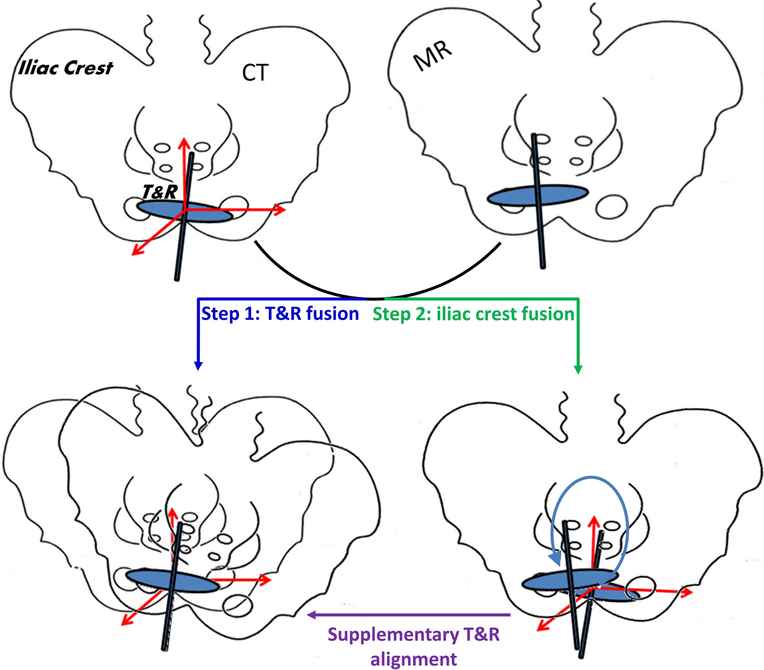
The illustration for the quantification of tandem and ring (T&R) displacements based on 2 rigid fusions between the computed tomography (CT) and magnetic resonance imaging (MRI) images.
The displacement of the T&R applicator set is defined as the six-degree shift (translation and rotation in 3 dimensions) that transforms the alignment result of step 2 to that of step 1 (referred to as supplementary T&R alignment), using the center of the ring as the coordinate origin. The assumption of this definition is that both the applicator set and patient’s pelvic bones are rigid bodies. Mathematically, let us denote the rotational and translational transformations for the fusion of the T&R only as Rt and Tt, respectively, where Rt is a 3 × 3 matrix representing the rotations around the axes of anterior–posterior (AP), lateral–medial (LM), and superior–inferior (SI) directions, and Tt is a 3-element vector representing the translation in the AP, LM, and SI directions. The counterparts for the fusion of the pelvic bones only are denoted as Rb and Tb, respectively. The supplementary rotational and translational transformations starting from the fusion result of step 2 are referred to as Rt-b and Tt-b, respectively. Thus, according to the coordinate transformation formula, 23 for any point, A0, in the T&R coordinate system, we have the following identity:

Rearranging equation (1) and considering A0 as the variable, we have


Thus, the displacement (ie, rotation angles and translation amplitudes in each of the 3 directions) can be obtained through Equations 2 and 3 in theory. The 3-dimensional (3D) translation amplitude is calculated as the square root of the sum of the squares of the translation amplitude in all 3 dimensions. The above analysis of T&R displacement is applied only for the first fraction of each patient.
Analysis of Rectal Dose Reduction
To evaluate the rectal dose reduction achieved using the balloon catheter, we compared the dose of the rectal point when the balloon is in place (referred to as balloon–rectum point) to the rectal point dose when a virtual rectal blade is in place (referred to as blade–rectum point). The definition of the rectal point complies with the International Commission on Radiation Units and Measurements 38 report, 24 as illustrated in Figure 4.

The definition of balloon–rectum point, blade–rectum point, and extra sparing distance d. The blue-dotted line indicates the virtual blade insertion.
Specifically, line A is defined as the line tangent to the balloon’s posterior edge, which is parallel to the longitudinal direction of the tandem. It was employed to approximate the position of posterior vaginal wall. Line B is defined as the line perpendicular to line A, which originates from the ring center. The balloon–rectum point is then defined as a point on line B that is 5 mm posterior to the intersection of line A and line B. Due to the fact that the data for treatments using a rectal blade were not available for the same patient set, a virtual rectal blade of the same actual dimensions was constructed in the CT data as if one were actually inserted. In this way, the blade–rectum point is readily defined on the same line B, 5 mm beyond the posterior edge of the virtual rectal blade. Assuming that the doses are D1 and D2 for the balloon–rectum point and the blade–rectum point, respectively, we can define the rectal dose reduction (as a percentage) using the balloon catheter, as compared to the virtual rectal blade, as

In addition, we define the sparing distance d as the distance between the balloon–rectum point and the blade–rectum point to indicate how much further the balloon may displace the rectum, when compared to the rectal blade.
Results
Rectum Sparing
Figure 5 shows the evaluation results of rectum sparing with the use of the balloon catheter as compared to the virtual rectal blade. Specifically, Figure 5A is the scatter chart presenting the relationship of further dose reduction percentage Φ with further sparing distance d for all 97 fractions, while Figure 5B illustrates the further sparing distance d for all fractions listed under each individual patient.
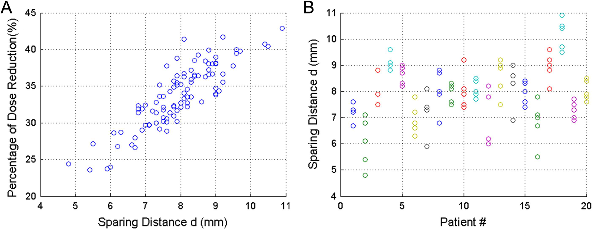
A, The relationship of dose reduction percentage Φ with sparing distance d for all 97 fractions. B, The sparing distance d of all fractions listed under each individual patient.
Statistically, the rectum-point dose can be further reduced by 33.7 ± 4.2% (from 276 ± 57 to 182 ± 38 cGy) corresponding to a mean sparing distance of 7.9 ± 1.1 mm when using the balloon instead of the rectal blade. The average of maximum d variation (the difference between the maximum d and minimum d) per patient is only 1.4 mm with a standard deviation of 0.6 mm, indicating that the rectum sparing function of the balloon is quite reproducible interfractionally.
Applicator Immobilization: A Sample Case
Figure 6 shows the results for both fusions of a sample patient. Besides the 3-view fusion images, the transformation parameters including a translation vector and 3D rotation angles for displacement calculation are also listed. As a result, the displacement of the T&R set is determined as [0.7, 3.8, 1.9] degree rotation around the axes of AP, LM, and SI directions, and [1.0, 3.0, 0.0] mm translation (ie, a 3.2 mm 3D translation) in the AP, LM, and SI directions. All other patient cases are analyzed in the same way, and the statistical results are listed below.

The fusion, based on the alignment of the tandem and ring (A) and pelvic bones (B), of primary computed tomography (CT) and secondary magnetic resonance imaging (MRI; in “spy glass”) for a representative patient case. Computed tomography uses grayscale while MRI is displayed in inverse grayscale. Window and level are adjusted for display purposes.
Applicator Immobilization: Statistical Results
Figure 7 shows the cumulative histogram of the displacement parameters, where each point on the curve indicates the percentage of 21 total patients (Y-axis) whose translation or rotation is not smaller than the displacement parameters indicated on the X-axis (note that, unlike the balloon study, the immobilization results involve only the first fraction of each patient). According to Figure 7A, the translation for half of the patients is less than approximately 2 mm in all directions, and the maximum translation is less than 10 mm. As indicated in Figure 7B, 50% of the patients possess a rotation angle no larger than 1° approximately in all planes, and the maximum rotation for all patients in a single plane is approximately 5°. The translation is smallest in the SI direction due to the fact that there is much less room for movement in the SI direction as compared to the LM or AP directions. The rotation around the LM axis is smallest owing to the least freedom of rotation.

The dose-volume histogram (DVH)–style cumulative histogram of all 21 patients, where each point indicates the percentage of patient whose (A) translation or (B) rotation is no smaller than indicated.
Table 1 shows the mean and standard deviation of translation and rotation in each direction/plane and those of 3D translation. As shown in Table 1, the average 3D translation is about 5 mm, and the mean rotation in any plane is less than 1.5°.
The Mean and Standard Deviation of Translation and Rotation Based on the First Fraction for 21 Patients.
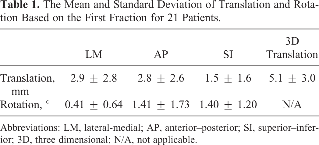
Abbreviations: LM, lateral-medial; AP, anterior–posterior; SI, superior–inferior; 3D, three dimensional; N/A, not applicable.
Discussion and Conclusion
The proposed balloon catheter system can potentially improve patient comfort as compared to other rectal retractor systems since it is inserted along with the ring applicator and almost no extra volume is introduced during the insertion, whereas greater pressure must be placed on the vagina to accomplish a successful insertion using other systems. In addition to potentially providing better patient comfort, the balloon catheter can also achieve better rectal sparing compared with the rectal blade since the size of the balloon can be adjusted to reach the optimal rectal retraction by injecting various amounts of fluid (in the current study, the same amount 10 cm3 of fluid was injected). However, the bigger the balloon size, the more discomfort the patient will experience. Seeking a balance between patient comfort and rectal dose sparing and subsequently tailoring the balloon size for each individual patient is an important topic that warrants further investigation.
As for the treatment uncertainties involved in HDR, the relative movement between the applicator set and the patient is a major concern. The commercially available solutions, again, may cause patient discomfort and they also possess potential safety risks (eg, uterine perforation). 14 We therefore propose an immobilization system that minimizes the applicator rotation and translation in relation to the patient’s pelvis with better reproducibility and potentially improved patient safety. Although the balloon and immobilization belt system were designed for the T&R treatments, they can be likewise applied for other applicators such as tandem and ovoid (T&O) after proper modification. For example, the immobilization belt can be used for T&O treatment if the bracket is accordingly modified to affix the T&O applicator set. The results of immobilization system evaluation show that the relative movement between applicator and the patient is minimal under most circumstances. The very rare large shifts (up to 10 mm/5°) are likely due to the patient movement during stretcher/couch switch.
At our institution, to maintain consistency, almost all of the patients were treated using the balloon catheter system and the actual treatment dosimetry data for the rectal blade system did not exist. As a result, the comparison of the two systems had to be made by replacing the balloon catheter with a virtual blade simulated in the treatment planning system. Moreover, the consequent rectal dosimetry evaluation was performed by comparing the rectal point doses instead of volumetric rectal dose (which would be the ideal parameter for evaluation) since the accurate rectal volume reconstruction with the virtual blade insertion is impossible. Since an appropriate assembly of the T&R applicator set (including the rectal blade) guarantees a fixed geometry, the rectal point dose calculated using simulated rectal blade should represent the actual rectal point dose with actual blade insertion in a fairly accurate way. Therefore, point dose comparison, rather than volumetric dose comparison, provides a more realistic and objective method of assessing the balloon system under the restrictions of our current clinical practice. In addition, the volumetric dose (eg, D2cc) is often highly correlated with the point dose and hence the analysis of rectum point dose represents a close approximation of that of volumetric dose.
To evaluate the efficacy of the immobilization system, the T&R movement is quantified with respect to the bony anatomy (iliac crest and pubic arch) rather than the high-risk clinical target volume (HRCTV). The rationale behind this can be explained as follows: (1) the relative movement between the T&R set and HRCTV is negligible since T&R set was restricted by the Smit Sleeve that is sutured to the cervical fornix region adjacent to the HRCTV and (2) the relative movement between T&R and bony anatomy can potentially vary the position and/or shape of OARs, which subsequently alter the OAR dose distribution from the original plan. For instance, the tilt of the tandem in the anterior direction can increase the dose to the bladder and decrease the dose to the rectum and the sigmoid. Therefore, we believe such evaluation method can be beneficial for dose consequence assessment caused by the applicator displacement. It is also worth noting that the relative movement estimation depends significantly on the accuracy and quality of the 2 rigid registration processes. Comparing the 2 registration processes, T&R alignments can possess larger uncertainty than pelvis bone registrations since the image contrast of the T&R is lower than that of the bones on the MR images. The fusion uncertainty can also be due to unsatisfactory image quality, such as intrinsic geometry distortion of MR images, CT/MR image artifacts, and so on. Two experienced clinicians worked on the fusions to minimize any possible fusion errors and/or uncertainties. An average uncertainty of about 1 mm/0.5° in each of 3 directions is estimated based on our registration experience.
Applicator movements are made minimal using our proposed immobilization system. However, the displacement of the applicator set tends to be larger when a significant rotation of the patient’s pelvis occurs between CT and MR imaging. Thus, the effectiveness of our immobilization device is subject to the reproducibility of patient position when the patient is moved from one supporting device to another. This underscores the importance of maintaining a stable patient position throughout the entire image-guided HDR procedure for the effective implementation of the belt immobilization system.
Despite the efficacy of our proposed treatment modification, it should be noted that, in addition to OAR sparing and applicator immobilization, another concern for image-guided HDR treatments of cervical cancer arises from the fact that the normal tissues may deform over the course of treatment. 25,26 Organs that change in size and/or shape during the course of treatment may ultimately compromise both tumor dose delivery and OAR sparing. For example, a patient’s bladder may be empty during CT simulation, but not before the treatment. Hence, it is vital to instruct the patient to empty their bladder and avoid drinking prior to both imaging and treatment.
In conclusion, a unique balloon design has been successfully implemented to spare the rectum during HDR treatments of cervical cancer. A patented immobilization system was utilized to minimize applicator movement, relative to the patient, to accurately deliver the planned treatment. With a retrospective analysis of archived patient data, minimal applicator movement was demonstrated, owing to the proposed immobilization system, and the rectal dose was significantly reduced compared to the rectal blade solution.
Footnotes
Declaration of Conflicting Interests
The design of the balloon and immobilization system is patented by MT&T, Inc. (Hawthorne, FL).
Funding
The author(s) received no financial support for the research, authorship, and/or publication of this article.