
Abstract
Intramodality ultrasound image-guided radiotherapy systems compare daily ultrasound to reference ultrasound images. Nevertheless, because the actual treatment planning is based on a reference computed tomography image, and not on a reference ultrasound image, their accuracy depends partially on the correct intermodality registration of the reference ultrasound and computed tomography images for treatment planning. The error propagation in daily patient positioning due to potential registration errors at the planning stage was assessed in this work. Five different scenarios were simulated involving shifts or rotations of ultrasound or computed tomography images. The consequences of several workflow procedures were tested with a phantom setup. As long as the reference ultrasound and computed tomography images are made to match, the patient will be in the correct treatment position. In an example with a phantom measurement, the accuracy of the performed manual fusion was found to be ≤2 mm. In clinical practice, manual registration of patient images is expected to be more difficult. Uncorrected mismatches will lead to a systematically incorrect final patient position because there will be no indication that there was a misregistration between the computed tomography and reference ultrasound images. In the treatment room, the fusion with the computed tomography image will not be visible and based on the ultrasound images the patient position seems correct.
Keywords
Introduction
Current quantitative ultrasound (US) image-guided radiotherapy (IGRT) systems 1 can be divided into two categories: intermodality and intramodality systems (Figure 1). With the intermodality systems, such as the B-mode acquisition and targeting system (BAT, Best Nomos, Pittsburg, Pennsylvania), 2,3 the US images acquired at the treatment stage (UStx) are compared to the reference computed tomography (CT) image acquired during the simulation stage. The intramodality approach entails comparison of a UStx image with a reference US (USref) image, acquired at the time of CT simulation, and therefore compares like with like. An example of this methodology is the Clarity system (Elekta, Stockholm, Sweden). 4,5
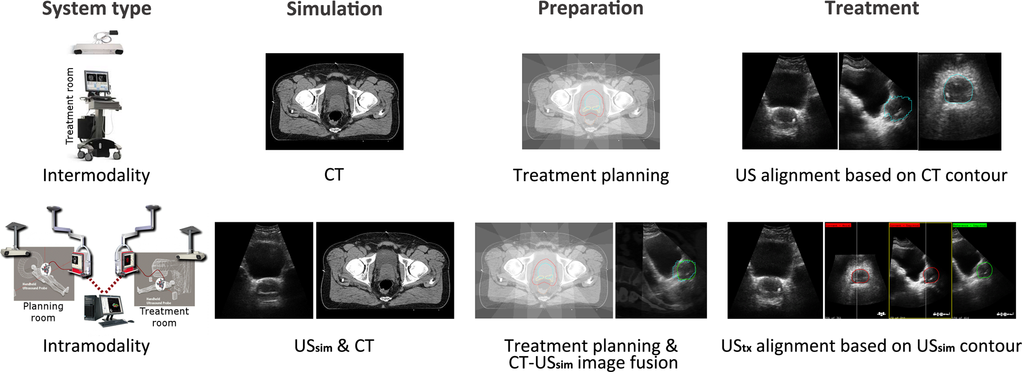
Schematic overview of the procedures during the different stages in the patient workflows for intermodality (top) and intramodality (bottom) ultrasound image-guided radiotherapy (US IGRT) systems. Images reproduced with kind permission of Fontanarosa et al. 1 System type images courtesy of Best Nomos (top) and Elekta (bottom).
Although intramodal alignment at the treatment stage is less sensitive to errors compared to the interimaging modality discrepancies 6 in intermodality systems, the complete workflow contains extra registration steps and procedures that may increase the error susceptibility. Because the actual treatment planning is based on a reference CT image, and not on a USref image, the accuracy of intramodality image guidance systems depends on the correct intermodality registration of the patient’s USref scan and the planning CT. In normal procedures, in which the USref and CT scans are made in direct succession and without any patient motion in between, the image fusion is an automatic process. When this automatic image fusion yields an incorrect match due to, for example, patient motion between the USref and the CT scans, there will be an alignment error between the CT and the USref scans, which, if not corrected, could propagate to the stage of the dose delivery.
The current manufacturer-recommended procedure is to rescan the CT and the US image in case of a known mismatch. However, since this is very time consuming, especially when it is not noticed immediately, an alternative approach to register the USref and CT images could be valuable. This could consist of manual shifting of either the CT or the USref image to accomplish a best fit between the two image modalities. This manual shifting relies on visual interpretation of common landmarks (eg, bladder neck) and thus adds an element of user dependence that may affect the accuracy of the positioning of intramodality systems.
In this work, we investigate the potential consequences for the intramodality approach when the CT and USref scans are not acquired in the same patient position, simulating uncertainties that may occur in daily practice due to a variety of reasons (eg, patient motion or laser offset). We will show how errors may propagate to the dose delivery stage, potentially jeopardizing patient safety. 7,8 In particular, this may also occur in cases where registration errors remain undetected. Methods for assessing potential errors and their causes proactively are very useful approaches for identifying and reducing errors and malfunctions 9 and should become more standard practice. With simple examples, we try to give a better understanding of the system and prevent errors due to simple mistakes or misinterpretations.
Methods
Intramodality 3-dimensional US IGRT System
The Clarity 3-dimensional (3D) US system consists of two US units, one in the CT room (US-Sim) and another one in the treatment room (US-Guide). At both units, a ceiling-mounted optical infrared position tracking system continuously tracks the US probe with reflective markers. This tracking system is calibrated through a room and probe calibration procedure with a dedicated calibration phantom, accomplishing the 3D reconstruction of the US volume referenced to the same room coordinate system with a tolerance level of 1 mm for each room as stated by the manufacturer.
During simulation, the patient is positioned on the CT table, and three external fiducials (metal markers) are patched on the patient’s skin at the outer intersection points of the room lasers (defining the CT reference point). The CT and USref images are acquired in quick succession with the patient in the same position. (The US scan is acquired with the patient aligned to the positioning laser outside the CT-bore. Directly following this US scan, the CT table is shifted inside the bore and a CT is acquired. The lasers correspond to the CT reference point through a calibration procedure.) On a workstation the simulation isocenter is identified on the CT, and the registered USref is overlayed to form a CT–US fusion. Once the treatment plan is complete, the isocenter information is transferred to the treatment unit and transformed from simulation to treatment coordinates. An initial isoshift (from the USref reference point to the radiation beams isocenter location) is reported and is based on the intermodality fusion of the patient USref and CT images.
For every radiotherapy fraction, the patient is aligned to the room lasers, and the acquired UStx scan is matched to the reference guidance structure of USref scan. Based on this match, the patient is shifted in three directions to realign the target with the radiation beams. 10
Workflow
We simulated five different scenarios compared to correct alignment (Table 1), mimicking errors that could occur during the simulation stage caused by, for example, laser offsets, patient motion (translations and rotations), or inaccurate room calibrations.
The five Different Scenarios in Comparison to the Correct Alignment on the Room Lasers.

Abbreviations: CT, computed tomography; USref, reference US.
The CT and USref images are assumed to be fused on the Clarity workstation using the alignment of the reference point (Figure 2). The USref reference point is defined as the intersection point of the room lasers (point L at intersection of dashed lines). The CT reference point is defined as either the intersection of the horizontal line connecting the lateral metal markers on the phantom/patient and the vertical line through the anterior marker (point MM) or the coordinates of the intersection of the room lasers (point L). The MM is same as the reference point used by the treatment planning system to propose an initial isoshift (from the reference point MM to the treatment isocenter).

Aligned and nonaligned patient/phantom positions. The origin of the ultrasound (US) system is defined with a room calibration and is made to coincide with the room laser intersection point (L). The origin of the CT can be defined as L or as the metal marker intersection point (MM) of the three markers. L and MM are identical when the patient is correctly aligned. A shift between these two occurs when there is a laser offset, when the patient moved in between scans, or when there is an incorrect room calibration of the US system.
When the automatic CT–USref image fusion yields an incorrect match, and this mismatch is not corrected before the start of the treatment, there will be a systematic misalignment between the CT and the USref scans. This may propagate into dose delivery errors, since this is based on the planning CT and the patient positioning is based on US guidance. When mismatches between the CT and USref scans are detected, the recommended (Clarity system user guide), yet time-consuming, procedure is to reacquire the scans. An alternative match correction approach is manual shifting of either the CT or the USref image. We also assessed the consequences of not applying a correction in case of a mismatch that could occur, for example, in case the mismatch was not noticed or deliberately left uncorrected.
Results
The consequences of the different actions in the first scenario are shown in Figure 3. The USref is made with the phantom/patient correctly aligned on the room lasers, while the CT was made with a misalignment. There are two choices for the CT reference point. If one chooses MM as the CT reference point, the automatic fusion will be correct and the proposed shifts from both the Clarity workstation and the US-Guide will direct the patient to the correct treatment position. If L is chosen as the CT reference point, the automatic fusion will not result in a correct alignment between the CT and the USref. Three actions can then be taken. The first one is obtaining a correct match by manual shifting of the CT toward the USref. This will result in correct treatment alignment for both the initial and the US-Guide proposed shifts. The second choice of action is shifting the USref toward the CT instead of the other way around. This will result in an incorrect initial proposed isoshift. Fortunately, since the USref and CT images are made to match, the position of the isocenter and radiation beams is correct. When the reference guidance structure will be made to match UStx, US-Guide will still direct the patient to the correct treatment position. The final option is not to correct the CT–USref misalignment. However, this will result in incorrect importing of the isocenter and radiation beams. Both are imported relative to the CT coordinates, and since the target on the USref is not made to match with the target on the CT, the isocenter of the USref will not be in the correct position in the US target volume. As a consequence, both the initial and the US-Guide proposed shifts will not result in a correct patient treatment position. There will be no indication that there was a misregistration between the CT and the USref. In the treatment room, the fusion with the CT will not be visible and based on the US images, the patient position seems correct. The errors will be made systematically, which could result in dose delivery errors.

The different actions for the scenario 1 (Table 1) and their consequences during dose delivery. The arrows in the last column depict the initial isoshift based on the reference ultrasound (USref). The large crosshairs depict the beam alignment after correction with the Clarity 3-dimensional (3D) ultrasound (US) unit in the treatment room (US-Guide). Only in the bottom situation, the alignment is incorrect during treatment which may affect the dose delivery.
The evaluation of the action consequences of all the scenarios is shown in Table 2. For the “Consequences for positioning” as can be seen in the right column of the table, it is assumed that the patient is positioned on the room lasers of the treatment room. However, the correct treatment alignment is independent of the initial patient position in the treatment room. The starting position in the treatment room will have an influence on the proposed US-Guide–based correction shift, yet the final treatment position will be the same. In case of rotational differences, none of the matching actions will lead to correct position guidance. In that case, the only solution is rescanning (both CT and USref) the patient.
Actions and Consequences of Registration Errors in the CT-USref Fusion.a

Abbreviations: MM, intersection of the lines connecting the metal markers; L, intersection point of the room lasers; CT, computed tomography; USref, reference US; US-Guide: Clarity 3DUS unit in the treatment room.
a In light gray, only the initial isoshift is incorrect. In the dark gray highlighted situations the final patient position, that is, the treatment position, is incorrect, which leads to erroneous dose delivery.
For translational shifts between the CT and the USref, as long as the patient USref and CT images are made to match, the isocenter from the CT is copied to the correct location on the USref, and US-Guide will direct the patient to the correct treatment position. Uncorrected mismatches will lead to a final incorrect patient position. Because the actual treatment planning is based on a reference CT, and not on a USref, it is preferred to use the CT registered with the metal markers and shift the USref to match the CT when manual fusion is employed for the match. With this approach, the initial isoshift calculated with the USref scan will be correct and will not question the US-Guide-based shift.
Discussion
In normal procedures, the intermodality CT-USref image fusion is an automated process, accomplished through a phantom calibration procedure. As long as the USref and CT scan are made in direct succession, without any patient motion in between, and all the calibrations and laser alignments are correct, even speed of sound (SOS) aberrations 11 –14 will be neutralized in workflows with this automatic CT–USref fusion. Nevertheless, one should be aware of possible errors in the intermodality CT–USref image fusion, since they may propagate to every treatment session as systematic dose delivery error.
In the case of SOS aberrations, correct automatic intermodality fusion could give a visual mismatch between the CT and the USref images. Yet, this mismatch is not because of patient motion, laser offsets, or incorrect calibration but due to SOS errors resulting in apparent shifts in the USref image. If the mismatch in the CT–USref fusion was corrected in this case, an error of another nature would be introduced instead of correcting for the mismatch error due to a shift. Therefore, the consequences described in Table 2 are only applicable to SOS corrected US-images. 12,15 The user should be aware that during treatment positioning when the following intramodality registration takes part, both US images should be SOS corrected or not. If SOS-corrected US images are made to match with non–SOS-corrected images, errors are introduced. For the example with a phantom measurement in Table A (Supplementary Material), a SOS correction was not necessary, since the calibration phantom is made of materials that have the same SOS as is assumed by the US system (1540 m/s). In clinical cases, manual CT–USref fusion without SOS correction may result in residual positioning errors or may even introduce them. This is a complex issue that was recently studied by Fontanarosa et al. 13,14
Furthermore, the accuracy of manual fusion depends on the matching skills of the operator and will therefore affect the accuracy of the positioning. For the intramodality matching, the interoperator variability was found to be 1.3 , 1.4 , and 1.8, respectively, in the left–right, anterior–posterior, and superior–inferior direction. 10 For manual intermodality matching, this variability is not expected to be smaller since the tissue boundaries in CT and US are depicted very differently. 16 –19 Although some of these errors might be intercepted by the safety margins used for treatment planning, and therefore will not always propagate to actual dose delivery errors, the recommended procedure in case of patient motion is always to rescan the patient with both CT and USref. Registration errors may still go undetected in which case Table 2 describes how errors will propagate; a necessity for safety assessments purposes. Table 2 may also serve as a guide to make US systems more robust against error propagation. Better understanding of the system can prevent misinterpretations and avoid mistakes.
Conclusion
The Clarity 3DUS guidance system is a robust IGRT device that guides the patient to the correct treatment position under the following conditions: the metal markers are used for the registration of the CT; SOS aberrations are taken into account 12,15 in intermodality image fusion, and preferably also during the intramodality procedures (both US images); and the CT scan and (SOS corrected) USref scan match. In the case of a mismatch, it is advised to rescan the patient with both CT and USref in direct succession with good patient stabilization to prevent patient motion in between the scans.
If one opts not to rescan, one could try to obtain a correct CT and USref fusion by shifting of the (SOS corrected) USref scan to the CT scan, which is the reference because the actual treatment planning is based on the CT and not on a USref. In case of rotations, this will not result in a correct match since the Clarity system cannot correct for rotations. Nonetheless, the accuracy of manual fusion depends on the matching skills of the operator. With an example with a phantom measurement (Supplementary Material), the accuracy of the manual fusion performed by an experienced user was found to be ≤2 mm, but in the case of a patient, the manual fusion may be more difficult. Therefore, in the case of a mismatch or rotations, we always recommend rescanning of the patient (both CT and USref). One should be aware that registration errors may go undetected.
Footnotes
Acknowledgments
The authors like to thank Elekta for their support and in particular Dr M. Lachaine for discussion
Declaration of Conflicting Interests
The author(s) declared no potential conflicts of interest with respect to the research, authorship, and/or publication of this article.
Funding
The author(s) disclosed receipt of the following financial support for the research, authorship, and/or publication of this article: SvdM is funded by GROW (School for Oncology and Developmental Biology, Maastricht University).
Abbreviations
References
Supplementary Material
Please find the following supplemental material available below.
For Open Access articles published under a Creative Commons License, all supplemental material carries the same license as the article it is associated with.
For non-Open Access articles published, all supplemental material carries a non-exclusive license, and permission requests for re-use of supplemental material or any part of supplemental material shall be sent directly to the copyright owner as specified in the copyright notice associated with the article.