
Abstract
Background:
In cancers of the head and neck, gross tumor or areas at risk of microscopic disease often lie close to the skin, while the skin itself may not be at risk. With intensity-modulated radiotherapy, setup errors can lead to underdosage of superficial structures because the collimator will not by default open beyond the skin surface to apply coverage in the air overlying the skin. Thus, small setup errors can move superficial structures out of field for some beams. Some planning systems allow for manually extrapolating fluence for beams tangential to superficial targets. It is unclear whether this problem is significant with tomotherapy.
Methods:
A head and neck phantom was utilized. A 3-mm bolus was used to represent the skin and allow placement of dosimeters at 3 mm depth. Thermoluminescent dosimeters were placed at reproducible points on the skin surface and at 3 mm depth. The phantom was irradiated, with the target volume deep to the thermoluminescent dosimeters receiving a dose of 5 Gy. This process was repeated with the phantom displaced 2.5 mm and again with a displacement of 5 mm. These displacements simulated setup errors that in clinical practice would correspond to bending or twisting of the neck that could not be corrected with rotations or translations.
Results:
When the phantom was displaced 2.5 mm, the dose measured at 3 mm depth was 99.2% (95.9%-102.5%) of the control. With a 5-mm displacement, the dose at 3 mm only dropped to 91.1% (88.8%-93.4%) of the control. Dose measured at skin surface decreased to a greater degree with such setup error.
Conclusions:
Dose at superficial depths degraded only slightly with 2.5-mm and even 5-mm displacements. With the tomotherapy system, superficial dose appears to be robust to clinically relevant setup errors. However, if the skin is at risk, bolus should be used to ensure adequate coverage.
Introduction
The nature of head and neck cancer, and the inherent problems with setting up patients in a reproducible manner, pose challenging issues with regard to radiotherapy dosimetry. Despite image guidance and immobilization techniques, setup error for portions of the head and neck that are distant from the regions utilized for image guidance can be substantial. These setup errors can lead to underdosage of structures that are relatively close to the skin. This underdosage arises in part due to the inability to calculate dose accurately in air and the difficulties that planning systems encounter when attempting to optimize dose in the buildup region. The resulting necessity of restraining the planning volumes to lie deeper than 2 to 3 mm from the skin surface leads to technically inadequate handling of setup error for superficial structures.
The primary factors that lead to the superficial structure dosimetry problem for head and neck cancer are: Clinical target volumes typically lie close to the skin. The skin itself is not generally at risk, and utilizing bolus material to address the problem is usually inappropriate (and may increase toxicity). The neck is flexible, resulting in positioning errors that cannot be corrected with simple translations and rotations. These errors are often 3 to 5 mm and have been reported to be as high as 1 cm in some cases.
1
–5
Planning margins cannot extend outside the body, and extending the planning volumes close to the skin results in planning system optimization problems. Artificially expanding planning volumes outside the body, using phantom bolus material for planning that is not present during treatment, has been implemented clinically.
6
However, this can detrimentally affect the dose distribution at depth.
There is no uniformly accepted approach to addressing such problems. The typical neck gross target volume (GTV) lies within 5 mm of the skin surface. Based on neck dissection data, the region at substantial risk of microscopic disease extends roughly 1 cm beyond this volume. 7 This is the clinical target volume (CTV), and it should not generally include the skin unless clinically involved, and thus it is reasonable to reduce the CTV to lie no closer than 2 to 3 mm from the skin surface. The planning target volume (PTV) expansion poses a more significant problem, as this expansion of 2 to 3 mm does not respect anatomical tissue planes. Preventing this PTV expansion from approaching the skin effectively reduces the robustness of superficial dose to setup error. With fixed beam intensity-modulated radiotherapy (IMRT), beams that pass tangentially across the skin near a superficial target structure will not have a margin of fluence beyond the skin and no dose cloud over the skin to provide coverage if the target structure is inadvertently displaced perpendicular to the skin surface.
Some planning systems support a practical method for dealing with this problem, fixed beam intensity-modulated multileaf collimator (MLC-based IMRT). This technique involves manually expanding the fluence of beams that are nearly tangential to regions where the target structures approach the skin. The technique effectively extrapolates radiotherapy coverage into the air overlying superficial structures, and on Varian systems, this technique is called “Skin Flash Tool.” This process is not easily made entirely automatic without compromising other optimization objectives, such as parotid sparing.
For tomotherapy, it is not clear how to address this potential problem. In this case, the beams arise from so many different directions that it is impractical to manually adjust fluence. In addition, the delivery is dynamic, with the MLC opening and closing as a fan of beamlets rotates around the patient in a spiral manner. However, this spiral delivery, and the possibility that relatively few of the beams will be tangential to the superficial targets, raises the hope that tomotherapy’s tolerance for setup error may be greater than that of fixed beam IMRT. Several investigators have noted that the tomotherapy planning system (TPS) tends to overestimate superficial dose. 8 –12 However, incidental surface dose tends to be higher with tomotherapy than with conventional IMRT or opposed lateral fields. 11 It has been noted that the tomotherapy system tends to produce fluence up to 7 mm beyond the skin surface. 10 We performed head and neck phantom experiments to evaluate tomotherapy’s robustness with regard to superficial coverage.
Materials and Methods
An anthropomorphic phantom (Accuray Inc, Sunnyvale, CA) with implanted bone density skull was utilized. Flat thermoluminescent dosimeter (TLD) packets were made by sealing calcium fluoride from commercially available dosimeters in flat plastic packets. The phantom was modified by labeling predefined superficial points with setup marks and temporary radiopaque markers (to be visible during computed tomography [CT] simulation) to identify the measurement sites. A 3-mm bolus material was placed over 2 of the points (point 1 and point 2), and this bolus covered the entire area of interest. The bolus represented the skin. Two additional measurement points were placed directly on the skin (points 3 and 4). The phantom is shown in Figure 1. Flat TLD packets were fastened in place for each measurement but were replaced by radiopaque markers during simulation. The radiopaque markers were removed after CT simulation.

The measurements were done using thin thermoluminescent dosimeters (TLDs) placed under and on the surface of a 3 mm bolus. This bolus was placed on the phantom’s right neck.
The phantom underwent CT simulation, and a target volume was drawn representing a GTV, CTV, and PTV. The PTV and CTV were truncated so as not to approach closer to the skin than 3 mm, shown in Figure 2, a depth consistent with other published work. 6 We generated a plan to treat with a dose of 5 Gy, larger than the typical head and neck cancer fraction size in order to increase the signal to noise ratio. Isodose curves are shown in Figure 3, and the median dose to the PTV was 5.10 Gy, per the TPS. Higher doses would exceed the range of our TLD calibrated dose range. The question under investigation did not require sparing the parotid glands, spinal cord, or oral cavity, and there were no optimization constraints on such structures or constraints on beam directions. Each measurement corresponded to a single delivery of 5 Gy. The target structure was sufficiently large relative to the separation between points 1 and 2, and between points 3 and 4, that the predicted and measured doses were in agreement within measurement error (TPS dose predictions were, respectively, 102.8%, 101.5%, 82.0%, and 83.8% for points 1-4). Two measurement points were chosen for the sake of this internal consistency check. As the measurements were similar, we combined points 1 and 2 measurements (3 mm deep) and points 3 and 4 measurements (surface) to improve the statistical accuracy.

The target GTV (maroon) was chosen to lie in the upper right neck, under the 3 mm bolus. Radiopaque markers were placed at the TLD locations for the CT, and replaced with TLDs during treatment. The GTV was expanded by 1 cm to construct a CTV (blue), which was expanded an additional 3 mm to define the PTV (red). Both the CTV and the PTV were truncated 3 mm deep to the skin surface. Other structures were drawn (parotid glands, spinal cord, and oral cavity) but did not impact the study. GTV indicates gross target volume; TLD, thermoluminescent dosimeter; PTV, planning target volume; CTV, clinical target volume; CT, computed tomography.

Isodose curves are shown for a total of 10 fractions of 5 Gy each. Each measurement corresponded to a single delivery of 5 Gy. Ten fractions were calculated because the Tomotherapy system cannot retreat a fraction, and multiple measurements were required. The legend on the right correlates colorwash with radiation dose, showing conformal coverage of the planning target volume (PTV) (red).
The phantom was positioned on the tomotherapy table and aligned with lasers to the marked isocenter. It was then scanned with megavoltage CT, and the table position was adjusted to align the bony anatomy. The phantom was then irradiated, and afterward the TLDs were removed and replaced. This process was then repeated (including the image-guided radiotherapy [IGRT] positioning scan) with the phantom translated to the right, a distance of 2.5 mm and 5 mm, and the measurements repeated. An unirradiated control TLD was carried along with the set of measurement TLDs.
As the phantom is rigid, it is not possible to simulate setup errors attributable to flexing of the neck. However, an equivalent measurement can be achieved by deliberately displacing the entire phantom by a predefined amount. Initially, the phantom was aligned per the setup marks, utilizing room lasers. An IGRT setup scan was done, and the anatomy was matched at the level of the tumor, which was in the upper neck (around C2). Anatomy was aligned to the bone. The tomotherapy table was then adjusted to correct the setup error. Two measurements were repeated for this nondisplaced baseline measurement. We then repeated this process, including the setup scan and table adjustment, and then shifted the table 2.5 mm and then 5 mm out of the radiation field. Measurements were repeated for all data points at these displacements. An unirradiated control TLD was carried along with the set of measurement TLDs. The TLDs were stored together with controls in the dark at room temperature before measuring the exposure. The primary direction of displacement of interest was lateral shift of the phantom so that the target volume was moved out of the field (to the patient’s right in this example), equivalent to moving the target into a region blocked by the MLC for fixed beam IMRT. We also evaluated displacements in other directions (left, table in/out, table up/down) and small rotations.
The average dose at 3 mm and average surface dose were calculated for shifts of 0, 2.5, and 5 mm. The primary displacement of interest shifted the measurement points out of the radiation field, that is, with the measurement points on the phantom’s right neck, the phantom was shifted to its right. Background was subtracted and standard deviations were calculated, with ratios of dose at a given displacement to the nondisplaced dose were calculated, using standard techniques to propagate errors.
Results
The depth of 3 mm is within the buildup region for 6 MV photons. The dose at 3 mm with no displacement was 4.22 ± 0.13 Gy (3%), a reasonable result, given the prescription dose (5 Gy) and the depth of measurement. The surface dose was 2.97 ± 0.05 Gy, roughly 70% of the 3 mm depth dose and 60% of the prescription dose. These doses are substantially less than the predictions of the TPS (full coverage at 3 mm depth, 83% at skin surface), consistent with the documented overestimation of superficial dose by the tomotherapy TPS. 8 –12
At a lateral displacement of 2.5 mm, the dose at 3 mm depth remained at 99.2% ± 3.3% of the nondisplaced measurement (control). With 5 mm displacement, this ratio remained relatively well preserved at 92.4% ± 4%. As the dose at 3 mm depth is only 84% of the prescription dose, due to being in the buildup region, a 5 mm shift reduces the dose at 3 mm to 78% of the prescription dose. This is a relatively insignificant change. Figure 4 illustrates the relative change in dose, relative to the superficial doses at the original position, for various shifts of the phantom laterally to the right (+) or left (−).
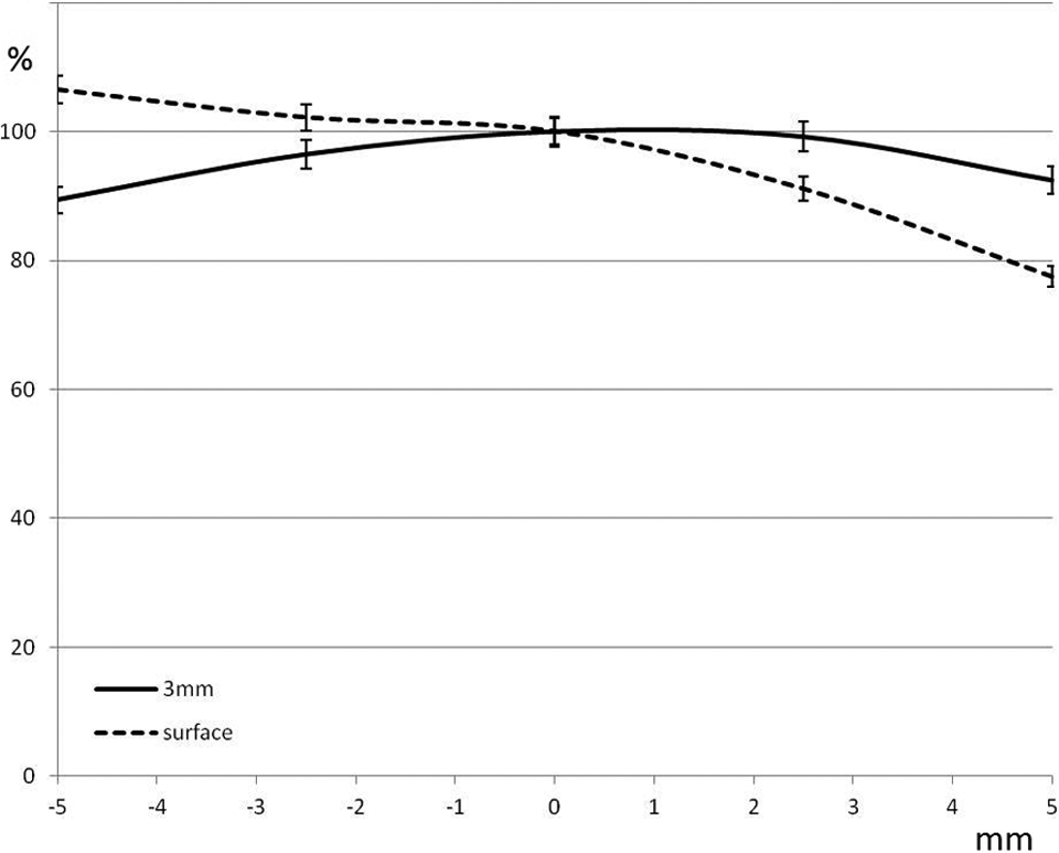
Fitted curves showing relative dose at the skin surface and at 3 mm depth as a function of displacement of the phantom out of the dose field (x-axis, in mm). A negative displacement corresponds to moving the skin deeper into the dose field. A value of 100% indicates no change in comparison to the measured value at 0 displacement, a value that is roughly 83% of the prescription dose at 3 mm depth. Moving the phantom out of the field had little impact on the dose at 3 mm depth for these displacements, and moving the phantom deeper into the dose field did not substantially increase the surface dose.
Skin surface doses were also carried along as a self-consistency check. At the 2.5 mm displacement, the skin surface dose dropped to 91.1% ± 2.3% of the nondisplaced skin surface measurement and dropped further to 77.5% ± 2.3% with 5 mm displacement. Relative to the prescription dose, the skin surface dose dropped from a baseline of 60% at zero displacement, down to 54%, and finally 45%, with increasing displacement laterally. While these changes were larger than the changes seen at 3 mm depth, they are less clinically relevant as the skin is not itself a target.
Displacements in other directions were also evaluated as well as small rotations in the sagittal and coronal axes. Displacements of the phantom 2.5 mm to the left (moving the measurement points deeper into the high dose volume), or moving the table up/down, or in/out by the same amount did not significantly affect the dose measured at surface or 3 mm depth. All of these measurements were within 97% to 102% of the nondisplaced measurements. At displacements of 5 mm in the same directions, the measured dose at 3 mm depth dropped to 90% in some cases, reflecting the positioning of the measurement points closer to a dose gradient. The skin surface dose remained relatively unchanged even for 5 mm displacements, remaining above 96% in all cases (96%-105% of the surface dose unshifted). The skin surface dose was limited by lack of buildup, even when the phantom was shifted such that the skin was directly within the target volume and remained relatively unchanged from baseline (Figure 4). Similarly, small angles (<3 degrees) did not significantly affect the measured doses. We did not address axial rotations because such rotations are accounted for in the tomotherapy system by altering the phase of the helical delivery. Rotations and displacements that do not contribute to positioning superficial structures out of the field do not have a bearing on the primary question being addressed, that is, whether the equivalent of a skin flash tool is required for tomotherapy.
Discussion
In the setting of head and neck cancer, the tomotherapy system appears to be robust with regard to setup error and dose to superficial structures. As such cases are routinely image guided, setup error of the magnitude studied here is unlikely to occur at the level of the IGRT setup match. However, flexibility of the neck could result in larger than desirable setup errors in the low neck, if the upper neck is used for IGRT setup. 4 We show that even with a 5 mm displacement, doses in the buildup region of 3 to 5 mm depth will remain at least at 90% of their baseline values. We demonstrated a minimal change in coverage with a 2.5 mm shift. With attention to detail, and appropriately replanning patients when anatomical changes warrant, it should be possible to keep displacements less than these ranges. There does not appear to be a need for the equivalent of a skin flash tool with tomotherapy, in the setting of head and neck cancer. A shift in the opposite direction (shifting the skin into the prescribed dose volume) did not substantially increase the surface dose, as it is limited by lack of buildup. Others have demonstrated consistent results for tomotherapy in the setting of breast cancer, showing that doses to superficial structures were relatively well preserved even for a 7 mm shift perpendicular to the skin surface. 10
While the dose at 3 mm depth was relatively unaffected by displacements less than 5 mm, it remains the case that delivered dose at superficial depths is less than that calculated by the current planning system. 9 –12 If the skin is truly at risk, or it is clinically essential that structures within the buildup region for 6 MV photons receive the prescribed dose, despite increased skin toxicity, treatment with bolus or the use of a more accurate algorithm (Monte Carlo) would be required. Our results would be expected to carry over to other rotational IMRT approaches, such as intensity-modulated arc therapy, although that remains a topic of future investigation. An understanding of the superficial dosimetry of the IMRT treatment delivery system is essential for clinicians, physicists, and dosimetrists involved in the treatment of patients with head and neck cancer.
Footnotes
Declaration of Conflicting Interests
The author(s) declared no potential conflicts of interest with respect to the research, authorship, and/or publication of this article.
Funding
The author(s) received no financial support for the research, authorship, and/or publication of this article.