
Abstract
Objectives
Part of the tumor localization methods in radiotherapy have poor real-time performance and may generate additional radiation. We propose a multimodal point cloud-based method for tumor localization in robotic ultrasound-guided radiotherapy, which only irradiates computed tomography (CT) during radiotherapy planning to avoid additional radiation.
Methods
The tumor position was determined using the CT point cloud, and the red green blue depth (RGBD) point cloud was used to determine body surface scanning location corresponding to the tumor location. The relationship between the CT point cloud and RGBD point cloud was established through multi-modal point cloud registration. The point cloud was then used for robot tumor localization through coordinate transformation between camera and robot.
Results
The maximum mean absolute error of the tumor location in the X, Y, and Z directions of the robot coordinate system were 0.781, 1.334, and 1.490 mm, respectively. The average point-to-point translation mean absolute error between the actual and predicted positions of the localization points was 1.847 mm. The maximum error in the random positioning experiment was 1.77 mm.
Conclusion
The proposed method is radiation free and has real-time performance, with tumor localization accuracy that meets the requirements of radiotherapy. The proposed method, which potentially reduces the risks associated with radiation exposure while ensuring efficient and accurate tumor localization, represents a promising advancement in the field of radiotherapy.
Keywords
Introduction
Ultrasound (US) is widely used for the diagnosis of internal tissues because of its advantages, such as easy operation, no radiation, and real-time imaging. US can be applied for visual image guidance in radiotherapy, such as tumor target localization, in vivo tissue motion monitoring, and three-dimensional (3D) anatomical structure visualization. 1 US imaging requires a high level of operator skill, and the pressure between the probe and the body surface, and the scanning position of the probe can affect the quality of US images.2,3 The combination of US and robotics provides a solution to these problems. 4 Through integration of robotic systems, these processes can be standardized for the substantial reduction of inconsistencies caused by human operations.
Currently, robotic image guidance systems are being developed in radiotherapy, where robots can replace medical technicians to achieve US guidance in radiotherapy and reduce radiotherapy errors through tumor localization.5,6 US-guided radiotherapy (UGRT) is used to improve the accuracy of radiotherapy by determining the location of the target area during radiotherapy through US imaging. 7 This technique takes full consideration of potential patient movements and displacement errors, including body movements, tumor shifts due to inter- or intraorgan dynamics, target area contraction, and positional inaccuracies, between fractionated treatments during radiotherapy. 8 These conditions can alter the radiotherapy dose distribution and affect the radiotherapy effect. Medical technologists can use US probes to determine tumor location to observe tumor changes and thus adjust the treatment plan to align the rays to the target area for precise radiotherapy. 9 US guidance in radiotherapy can be achieved by a robot with integrated powerful sensors instead of a physician; Seitz et al 7 designed a robotic US-guided respiratory and motion control system that integrates the control functions of the US robot system and image processing functions into the same software platform to verify the feasibility of robotic UGRT.
Multimodal point clouds are point cloud data acquired by multiple sensors, devices, or methods in 3D space, and they often contain information from different physical properties or sources. By combining information from different sources, multimodal point clouds can provide richer information. 10 Multimodal point clouds are applied by acquiring local point clouds for stitching by depth cameras multiple times to obtain red green blue depth (RGBD) point cloud models. The models were aligned with computed tomography (CT) contours in the simulated localization phase to establish the relationship between biological anatomical structures and multimodal point clouds, ie, by visualizing 3D multimodal point cloud models, to find the coordinates of the body surface RGBD point cloud corresponding to the in vivo tumor CT point cloud, and to establish the point cloud coordinate conversion relationship between the in vivo tumor CT point cloud, the body surface CT point cloud, and the body surface RGBD point cloud. As a result, the point cloud can be used for robotic UGRT through the coordinate conversion between the depth camera and the robot.
We propose a multimodal point cloud-based radiation-free and real-time robotic tumor localization method. The localization accuracy meets the demand of radiotherapy, which can ensure the real-time safety and accuracy of tumor localization and good application prospects of the proposed method in clinical applications. The novelties of this work are as follows: (1) the introduction of computer vision to provide high-precision tumor localization and a highly visualized 3D point cloud model, (2) the combination of CT and RGBD point clouds into a multimodal point cloud that can obtain tumor position by the CT point cloud and realize tumor localization by coordinate conversion of RGBD point cloud; (3) replacement of the medical technician with a robot to realize ultrasonic probe localization during radiotherapy with high real-time performance; (4) reduced radiation dose and waiting time compared with other imaging methods when applied to tumor localization between fractionated radiotherapy sessions.
In summary, we developed a radiation-free robotic tumor localization method based on multimodal point clouds. This method effectively reduces the additional radiation dose during fractionated radiotherapy sessions. In addition, this procedure not only meets radiotherapy demands but also ensures the safety and accuracy of tumor localization. Thus, the proposed methods show a great potential for clinical applications. We integrated computer vision technology and robotics to improve the precision and real-time capabilities of tumor localization. With continuous technological advancement and further application in clinical settings, the multimodal point cloud-based robotic UGRT system is poised to contribute considerably to the field of radiotherapy technology.
Materials and Methods
Experimental Setup
Figure 1 shows the robotic UGRT tumor localization system. The system mainly contains a 6 degrees of freedom collaborative robot (RM65-6F, Realman, Beijing, China), an UGRT system (Clarity, Elekta, Stockholm, Sweden), a depth camera (RealSense D435i, Intel California, USA), female pelvic phantom model (404A, CIRS, Virginia, USA), and U-shaped robotic treatment bed mounting bracket.

Setup of robotic UGRT tumor localization system.
Figure 2 demonstrates the workflow of our robotic UGRT. First, the CT and RGBD point clouds are acquired and processed using different methods. Subsequently, multimodal point cloud alignment is performed to achieve precise registration of the CT and RGBD point clouds. Next, coordinate transformation is carried out to determine the location of the tumor, which is then converted into the robot coordinates. Finally, the robot performs an ultrasound scan based on the determined position, enabling precise localization and scanning of the tumor.

System framework of robotic UGRT based on multimodal point cloud.
System Coordinate System Conversion
Before the robot performs US guidance in radiotherapy, the conversion relationship between the coordinate systems in the system needs to be determined. Figure 3 shows the coordinate system conversion. The system takes the robot base coordinate system as the world coordinate system and completes the conversion between the robot base, robot end tool, and camera coordinate systems. Based on the demand of radiotherapy scene, the depth camera is mounted on the robot end tool, and this mounting method needs to solve the conversion relationship between the camera and robot end tool coordinate systems.
11
For any two poses during robot movement, the following equation holds:

System coordinate system conversion.
The above equation is converted to the following:
 , the form
  , and
, and  . The conversion matrix
In the process of coordinate system conversion, system errors mainly stem from two aspects: hardware and software. In terms of hardware, errors are primarily associated with the resolution and accuracy of the camera and sensors, the stability of the camera and end tool fixation, as well as the joints and structural inaccuracies of the robotic arm. On the software side, errors mainly arise from the external parameter calibration of the camera and the hand-eye transformation. The accuracy of these calibrations is influenced by noise in the camera images, changes in ambient lighting, and the position and orientation of the calibration plate. To enhance the accuracy of coordinate system conversion, we collected extensive external parameter calibration data and hand-eye calibration data, and performed multiple repeated calculations.
In addition, given that the scene acquired by the camera is the scene in the radiotherapy treatment phase, and the positioning CT as the reference scene is the scene generated in the planning phase, the conversion of the camera coordinate system to the CT imaging coordinate system needs to be performed after the system coordinate system calibration. The 3D point cloud contour obtained by point cloud stitching was aligned with the contour of the positioning CT image. Thus, the pose in the treatment phase was consistent with that in the planning phase.
Point Cloud pre-Processing
The point cloud of the body surface after radiotherapy positional calibration was acquired and processed by the depth camera. The point cloud information of the tumor area was acquired using Intel RealSense Viewer software. To extract the point clouds corresponding to the localization points accurately, we filtered the original point clouds and de-noised them by combining gaussian filter and density-based spatial clustering of applications with noise. 12 Subsequently, the point cloud was down-sampled to improve the efficiency of point cloud processing. The entire preprocessing stage primarily comprised three steps, namely, point cloud filtering, denoising, and down-sampling, which altogether lasted approximately 5 s. Under a single pose, the sampling period for point cloud data was approximately 20–30 s. During this interval, we collected 10–15 frames of point cloud data, from which the best frame was selected for subsequent processing. To ensure that the geometric information of the point cloud remained unchanged, we selected voxel down-sampling based on the geometric distribution of the point cloud after down-sampling.
After refining and reducing the data set, we then proceeded to more intricate procedures of point cloud manipulation for further data refinement for detailed analysis and application. The point cloud processing process advanced as follows: (a) extraction of fast point feature histogram (FPFH) for point cloud stitching and alignment, (b) CT point cloud generation, (c) multiview RGBD point cloud stitching, (d) point cloud noise reduction and down-sampling processing, (e) RGBD and CT point cloud alignment, (f) construction of 3D multimodal point cloud model, and (g) calculation of point cloud normal-vector.
Multimodal Point Cloud Alignment
CT point cloud was acquired by 3D Slicer software through 3DCT after volume reconstruction, and the RGBD point cloud was acquired by a depth camera. Simulated positioning and radiotherapy were performed in different rooms, and when the RGBD point cloud was aligned with the positioning CT point cloud, the camera coordinate system to CT imaging coordinate system conversion relationship was calculated. In addition, the camera and CT point clouds have different data characteristics and acquisition methods, which need to be aligned for subsequent processing and analysis. The CT and RGBD point clouds had different sampling densities, size, and features, and the parameters were adjusted to achieve optimal alignment.
Figure 4 illustrates the steps for computing point cloud normals. The multimodal point cloud alignment was an alignment between the CT and RGBD point clouds. The alignment method of multimodal point clouds is as follows: the point cloud images of both modalities were coarsely aligned by Align function in Cloud Compare V2.11.3 software and finely aligned using iterative closest point (ICP) algorithm. 13 The coarse alignment was implemented based on local feature descriptors to provide a better initial position for fine alignment. The fine alignment criterion is based on the distance closest principle to determine the point pair based on coarse alignment, and the error converges to the specified range by determining the objective function and solving rigid transformation. The depth camera needs to take multi-viewpoint clouds to obtain the complete RGBD point cloud, which promotes alignment with the CT point cloud and reduces the multimodal point cloud alignment error. In addition, a FPFH combined with ICP alignment algorithm was used to stitch the local point clouds.13,14

Steps of point-cloud normal-vector calculation. A. Calculate the nearest neighbors of path points through the combination of the radius nearest neighbor and K-nearest neighbor algorithms. B. Apply the least squares method to fit the point cloud plane composed of various nearest neighbor points around each path point. C. Use the PCA algorithm for calculation of the normal vector of the fitted plane on the path point. PCA, principal components analysis.
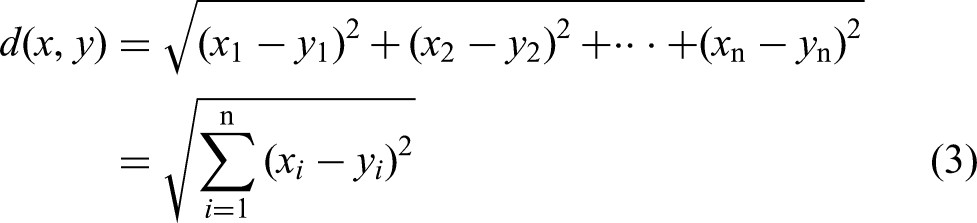
The normal vector calculation requires fitting the plane. As shown in Figure 4 (A), the radius K-nearest neighbor (RKNN) algorithm was used to search for the nearest neighboring point cloud points used to fit the plane within the set radius. And as shown in Figure 4 (B), the least squares method was used to fit the plane to the point cloud. The nearest neighbor distance was calculated using the Euclidean distance calculation with the following formula:

The normal vector of plane P is considered the normal vector of the current point

Tumor Localization
The system can obtain the coordinates of the localization point of tumor location in the robot-based coordinate system by coordinate conversion. First, the RGBD point cloud was obtained from the depth camera, and tumor position was determined with reference to the localization CT point cloud and localization points on the body surface. It should be noted that the localization points are determined by senior doctors through multimodal point cloud model. These points correspond to the location of the tumor, and moving the US probe to these points can effectively detect the tumor and achieve tumor localization. Then, the coordinates of the RGBD point cloud corresponding to tumor location were obtained from the CT point cloud as coordinates of the tumor localization point. Then, the point cloud coordinates of the tumor localization point were converted to the robot-based coordinate system by the camera coordinate system to obtain the predicted tumor localization coordinates. Finally, the point cloud coordinates of the tumor localization point and point cloud normal vector were used to determine the end position of the robot. As a result, the probe was as vertical as possible to the body surface.
The positioning accuracy was verified using repetitive positioning and random positioning methods. The repetitive positioning method repeats the positioning of the same marker point in each area to verify the repetitive positioning capability of the system. The mean absolute error (MAE) in the X, Y, and Z directions of the robot base coordinate system was used as a measure because it directly represents the average size of errors between predicted and actual positions, offers a straightforward calculation, and shows less sensitivity to outliers. In addition, evaluated the repeat positioning accuracy by calculating the MAE of point-to-point translation between the actual and predicted positions of the US probe in each region. The random positioning method randomly selects several localization points from the surface of the phantom model and compares the maximum positioning error of each point in X, Y, and Z directions with the positioning accuracy of the US probe required for radiotherapy to verify the clinical feasibility and applicability of the positioning method.
For precise and standardized operation, the control and operation of the robot are crucial for the successful implementation of UGRT. Therefore, the robot should be controlled by an US doctor proficient in robotic operations, particularly during the fine-tuning stage of probe positioning. For our experiments, an US specialist was invited as a technical consultant and received training in robot control. After adequate training, the US doctor successfully operated the robotic arm and achieved probe scanning and image acquisition results that are comparable to those obtained in manual US examinations.
Results
Point Cloud Processing
The point cloud processing workflow involves several key steps: extraction of local features using FPFH, generation of CT point cloud, stitching of multiview RGBD point clouds, noise reduction and down-sampling, alignment of the camera and CT point clouds, construction of a 3D multimodal point cloud model, and calculation of normal vectors. Figures 5–9 show the results of point cloud processing.

CT point cloud generation process. A. Contour and organ outline for phantom model CT. B. CT point cloud generated by 3D Slicer.

RGBD point cloud stitching under multiple views. A. Local point clouds under different views for point cloud stitching. B. Point cloud stitching results. RGBD, red green blue depth.

Denoising and down-sampling results of CT and RGBD point clouds. RGBD, red green blue depth.

Camera and CT point clouds generated a 3D multimodal point cloud model by coarse and fine alignments of point cloud A. Align coarse alignment result B. ICP fine alignment result. Align coarse alignment provides a better initial position for ICP fine alignment, and ICP fine alignment converges the alignment error to the specified range on the basis of Align coarse alignment. The point cloud coarse alignment and fine alignment improve the matching of the scale, edge, and other features of the multimodal point cloud. ICP, iterative closest point.

Point cloud normal vector calculation process. A. Original point cloud B. Point cloud after down-sampling. C. Calculation result on point cloud normal vector.
The probe position was determined through a precise coordinate transformation process. Specifically, the coordinates of surface positioning points were converted into the robot's base coordinate system, with the robot controlling the probe to move to the designated location. The RKNN algorithm was used to calculate the nearest neighbor points around the target point to fit the plane. Parameter max_nn was set to 20 based on point cloud density, and the maximum search radius was 0.05. The plane formed by these points was fitted by the least squares method, and the normal vector of the plane in which the target point is located was obtained by the PCA algorithm. Figure 9 shows the results of point cloud normal vector acquisition. Subsequently, through utilization of the normal vectors derived from the point cloud, the US probe was adjusted to be as perpendicular as possible to the body surface. Then, the probe orientation was finely adjusted based on image quality to ensure optimal imaging results.
Verification of Localization Accuracy
To verify the tumor localization accuracy of the described method, we selected four representative regions (Figure 10) in the female pelvic phantom 404A for verification. The depth camera was clamped by the robot and positioned by localization points in each region. For each area, coordinates of the marker point cloud were obtained using the depth camera in multiple positions and converted to the robot-based coordinate system for comparison with the real position to verify the repeat positioning error.

Phantom positioning area.
Localization experiments were arranged as shown in Figure 11, with the white body surface localization points located in four localization areas and the depth camera placed at the end of the robot. The robot carried the depth camera to acquire the coordinates of the same localization point in different positions, and the coordinates were used to calculate the MAE after coordinate conversion. Repeat positioning error validation experiments were conducted to obtain the tumor body surface localization points by multi-modal point cloud, and the coordinates of the robot base coordinate system obtained from the point cloud coordinates of the localization points after conversion were used as gold standard to evaluate the repeat positioning error under multiple poses of the camera. Table 1 shows the MAE of localization points in each region. The MAE of localization points were calculated as the absolute value of the difference between the actual positions regarded as gold standard and the predicted. From Table 1, the maximum values of MAE in the X, Y, and Z directions of the robot-based coordinate system were 0.781, 1.334, and 1.490 mm, respectively. Figure 12 shows that the point-to-point translation MAE between the actual and predicted positions of the localization points in each region of the ultrasonic probe was 1.847 mm, with a maximum translation error of 3.653 mm (Region 4) and a minimum of 0.584 mm (Region 1). The data used for error calculations were obtained from the robot end-tool coordinate values displayed on the robot demonstrator.

Positioning experimental setup. Positioning experiments included repeated positioning error verification experiments of the same localization point under different camera positions and random positioning accuracy verification experiments of randomly selected localization points.
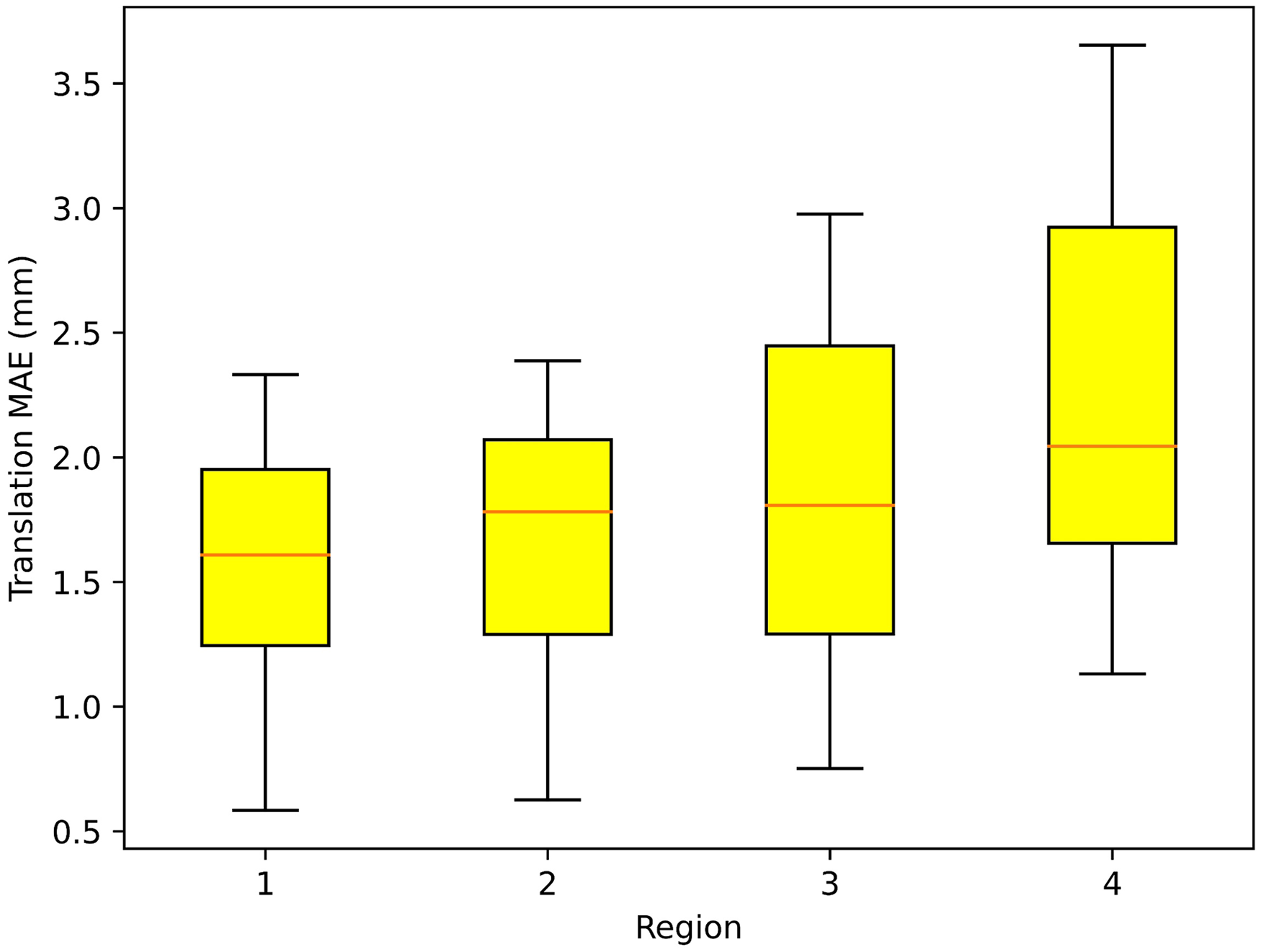
Translational MAE between the actual and predicted positions of the localization points in each region. Region 1 has a flat surface, highest accuracy of camera identification, lowest translational MAE, and the best localization effect. Regions 2 and 3 had certain concave and convex surfaces, with an average localization effect, and the translational MAE values were between Regions 1 and 4. Region 4 showed a large surface variation, highest translational MAE, and poorest localization effect. From the results of 10 repeated positioning experiments with 40 point-to-point distance calculations, the translational MAE of the 40 sets of data was 1.847 mm, the minimum translational error was 0.584 mm in Region 1, and the maximum was 3.653 mm in Region 4. MAE, mean absolute error.
Repeat Positioning Error Verification Experimental Results.

Random positioning accuracy verification experiments compared the positioning results of eight randomly selected localization points after coordinate conversion with the actual positions, and the comparison results are shown in Table 2.
Random Positioning Accuracy Verification Experimental Results.

Discussion
Multimodal point clouds have more available information than single types, especially the coordinate information displayed in real time in RGBD point clouds and tumor location information in CT point clouds. To improve tumor localization accuracy, we aligned the point clouds under different modalities and achieved tumor localization by fusing point cloud images. After converting the coordinates of localization points in the camera coordinate system to the robot-based coordinate system, the robot can clamp the US probe to achieve probe localization based on the coordinates of localization points. 15 Before positioning the probe, the probe attitude at the end of the robot was determined based on the point cloud normal vector. As a result, the axis direction of the US probe was normal to the body surface to achieve optimal US imaging. Otherwise, tumor localization will be affected by the lack of image information caused by the improper positioning attitude of the probe. Under the premise of using point cloud normal vector direction as the probe axial direction, the force in each direction was read in real time by the force sensor at the end of the robot to achieve high-quality US guidance with safety.16,17 Currently, medical robots for US imaging are still in the research phase, focusing on US image processing and force adaptation strategies and still lacking clinical studies and appropriate safety strategies. 18 Subsequent research may focus on artificial intelligence and augmented reality.
In our research, a multimodal point cloud-based tumor localization method for robotic UGRT was proposed to provide a solution for UGRT by achieving tumor localization through computer vision. The method displayed tumor location in the camera coordinate system through the multimodal point cloud, which was then transferred to the robot-based coordinate system through coordinate transformation. The US probe was moved to the position-optimized localization point to perform US guidance in radiotherapy by robot kinematic analysis. 19 The experimental results validate the feasibility of the described method. The robot achieved a high success rate of positioning based on multimodal point clouds, whereas the time and accuracy costs associated with coordinate system calibration converged to low values.
Compared with the CT tumor localization methods commonly used in radiotherapy, the described method allows obtaining tumor location information in real time during radiotherapy without waiting for CT scan results and without using additional radiation. However, the described method also has disadvantages, which may result in errors caused by the calibration accuracy of the coordinate system and operation of the medical technician. Both methods have their advantages and disadvantages that need to be considered in clinical applications.
When performing tumor localization in non-flat areas of the body surface, the point cloud acquired by the robot clamping depth camera in a fixed initial position may be insufficient to support a stable and efficient US scan, 20 and the camera is required to acquire the point cloud coordinate information at the localization point in real time in multiple positions and to build a 3D point cloud from the robot-environment interaction to improve localization accuracy and efficiency. Furthermore, the main challenge in tumor localization is the dynamic nature of tumors, which is primarily attributed to the movement caused by respiration. Currently, our method fails to meet the requirements for dynamic tumor monitoring under respiratory motion.
To mitigate the effect of tumor movement, we proposed a solution involving US examinations during short breath-hold periods. Given that CT scans during the simulation positioning phase were conducted under breath-hold conditions, for guaranteed consistency between the RGBD point cloud and CT point cloud contours, RGBD point cloud acquisition was performed under the same settings. In UGRT, US examinations are mainly aimed at achieving registration with the positioning of CT images and monitoring of significant changes in a tumor's position. Given that the scanning position is fixed and singular, and each US scan is brief, a short breath-hold will not cause discomfort to the patient.
Future work will focus on further clinical trials, which will be conducted to validate the clinical feasibility of the proposed method and explore potential applications in remote US examinations to provide the same level of treatment in areas lacking medical resources. In addition, future research may emphasize the integration of artificial intelligence and augmented reality to improve the capabilities and safety of medical robots for US imaging.
Conclusions
Based on robotic UGRT technology, the tumor localization of US probe by multimodal point cloud is beneficial to the formulation and correction of radiotherapy plan. The multimodal point cloud, which consists of a combination of CT and RGBD point clouds, can obtain the tumor position by the CT point cloud and realize tumor localization by the coordinate conversion of the RGBD point cloud, which promotes the precise detection of tumors in radiotherapy. The method described in this study uses multimodal point cloud to achieve robotic tumor localization in UGRT, which has good multimodal point clouds prospects for clinical applications.
Footnotes
Abbreviations
Acknowledgments
This work has obtained permission from physicists and technicians who have contributed to the manuscript. This work does not use editing or translation services.
Authorship Contribution
Lintao Song: Resources, Software, Methodology, Data Curation, Revision of manuscript, Visualization; Qixuan Li: Conceptualization, Methodology, Software, Investigation, Formal Analysis, Writing Original Draft, Visualization; Sai Zhang: Resources, Data Curation, Visualization; Kangkang Sun: Visualization, Investigation; Wei Chen: Resources, Supervision; Heng Zhang: Software, Data Curation; Yibo Wang: Writing Review, Investigation, Supervision; Zhuqing Jiao: Writing Review, Validation, Supervision; Xinye Ni: Conceptualization, Funding Acquisition, Resources, Supervision.
Data Availability
The data that support the findings of this study are available from the corresponding author upon reasonable request.
Declaration of Conflicting Interests
The authors declared no potential conflicts of interest with respect to the research, authorship, and/or publication of this article.
Ethical Statement
The experiments in this study did not involve human or animal studies, so no ethical permission was required. The experiments in this study did not involve human or animal studies and therefore did not require the written/verbal consent of the patient or the patient's parents/caregivers.
Funding
The authors disclosed receipt of the following financial support for the research, authorship, and/or publication of this article: This work was supported by General Program of National Natural Science Foundation of China (Grant No. 62371243), Jiangsu Provincial Natural Science Foundation General Project (Grant No. BK20231190), Jiangsu Provincial Health Commission General Project (Grant No. M2020006), Jiangsu Provincial Medical Key Discipline (Laboratory) Cultivation Unit (Grant No. JSDW202237), Changzhou Social Development Project (Grant No. CE20235063) and Jiangsu Provincial Key Research and Development Program Social Development Project (Grant No. BE2022720). This work was also sponsored by Qing Lan Project of Jiangsu Province.
Participating Investigators
Qianyi Xi: participated in writing editing of the manuscript; Fan Zhang: participated in language editing of the manuscript; Mu He: critically reviewed the study proposal; Xie Kai: served as scientific advisors.