
Abstract
Keywords
Introduction
Precision and accuracy are vital in stereotactic body radiotherapy (SBRT) as high biologically effective dose (BED) is delivered in fewer fractions compared to conventional radiotherapy treatment schema. This is particularly true in spine SBRT, for which highly conformal dose distributions are designed not only to treat cancerous tumors with narrow margins (on the order of millimeters) but also to spare adjacent radiosensitive organs at risk (OARs), especially the spinal cord. Due to the narrow margins and steep dose gradients between the target and the spinal cord in spine SBRT, millimeters of patient misalignment can result in treatment failure due to underdosage of the disease and/or patient injury due to overdosage of the spinal cord. Thus, monitoring patient set up during treatment delivery can prevent such underdosage/overdosage and thereby reduce the possibility of post-radiotherapy recurrences/complications. Avoiding spinal cord injury while maximizing the target coverage is one of the main concerns in spinal tumor treatment to avoid radiation-induced myelopathy or long-term problems such as hypoplasia, especially in pediatric patients.1-4 Patients are set up before each treatment and their mobility is controlled during treatment delivery with rigid immobilization devices. However, involuntary motion such as physiologic muscular contractions or patient repositioning may still occur. Despite such need for countermeasures against unexpected movements during treatment, most current linac-based image guided radiotherapy (IGRT) approaches manage interfraction motion and patient set up accuracy before and between treatments, but do not often account for intrafraction uncertainties. There are a few IGRT options providing intrafraction motion monitoring. Those techniques often require specialized equipment and/or invasive implants (e.g., electromagnetic tracking or ultrasound-guidance), or use surrogates rather than direct tracking of patient anatomy (e.g., surface guidance) and most are not applicable to spine SBRT.5-11 In this work we describe a cost effective, highly accessible and non-invasive intrafraction motion monitoring approach with more readily available equipment that directly tracks patient anatomy.
Modern linear accelerators are equipped with an on-board imager (OBI), capable of generating high-contrast kV planar images, as well as volumetric cone beam CT (CBCT) images of the patient's internal anatomy at the time of treatment. The kV imaging dose taken with OBI is negligible: ∼1mGy at isocenter from an orthogonal pair, ∼1cGy to skin per arc (2-4 per spine SBRT volumetric modulated arc therapy [VMAT] treatment). 12 Using the OBI system and advanced IGRT and motion package available on the Varian Truebeam v2.5 and later (Varian Medical Systems, Palo Alto, CA), kV images can be acquired during treatment delivery for intrafraction motion management without exposing the patient to significant imaging radiation dose.
The OBI based IGRT using fiducial markers has been widely used in clinics to increase set up accuracy and treatment safety.13-17 In addition to helping account for interfraction changes, fiducial marker location can be tracked during treatment to help account for intrafraction changes. One available approach is using the triggered imaging and marker localization feature available with the TrueBeam platform. The software searches for marker locations on kV images acquired with OBI and gives quantitative feedback on how close markers are to the expected location. If the marker is outside of a pre-set tolerance threshold distance, indicator color changes and an operator can choose to stop treatment to adjust or, if the auto beam hold (ABH) function is active, the treatment beam can be automatically paused. In various studies, intrafraction motion was detected in a surprisingly large percentage of fractions with this marker tracking technique despite standard patient immobilization (eg, shift recommended in 44% of fractions for prostate treatment, 9 second localization with CBCT was required in 11.6% of liver SBRT patients. 18 ) Thus, intrafraction motion tracking can help detect clinically meaningful patient motion that happens rather frequently and reduce radiotherapy related morbidity.19-21 While these provide examples where marker tracking can improve precision in radiotherapy, the patterns and underlying physiologic causes of motion in the above mentioned scenarios (eg, respiration or peristalsis-induced motion) may be different compared to the context of spine radiotherapy. 22 However, there still remain potential non-respiratory sources of intrafraction motion, which warrant similar motion monitoring of the patient during radiation delivery for extremely precise spine SBRT. While marker tracking offers precise intrafraction motion management, it also requires invasive implants. In this work, we introduce an intrafractional IGRT approach for spine SBRT without marker implants by utilizing the triggered kV imaging feature of the Truebeam advanced imaging package. Instead of implanted fiducial markers, endogenous patient anatomy (vertebral body and spinous process) and/or exogenous orthopedic hardware (if already implanted) were used to track motion. These structures were drawn as IGRT structures on the planning CT and projected onto triggered kV images for a qualitative visual guide. The method was tested with an anthropomorphic phantom to quantify precision and utility of this technique in a controlled setting. The results from implementing this methodology clinically for intrafraction motion management during treatment of spine SBRT patients are also presented to assess practicality and demonstrate feasibility.
Methods
Phantom Test
To investigate the feasibility of the method and realistic precision including observer uncertainty in a controlled experiment, triggered kV imaging for intrafraction motion management was evaluated with an Alderson RANDO anthropomorphic phantom (Alderson Research Laboratories, Inc., Long Island City, NY) by simulating spine SBRT treatments to the thoracic spine (T-spine) and lumbar spine (L-spine). Hypothetical tumors at T9 and L3 were considered. Disease located in the cervical spine (C-spine) was excluded from this research due to the location and shape of the C-spine. As C-spine is in the shoulder level, adjacent bony structures obstruct the imaging beam path. This combined with narrow intervertebral gaps that are not well-aligned in the transverse plane make it difficult to visually differentiate between vertebral structures on kV images. Additionally, anterior-posterior (AP)/posterior-anterior (PA) images could be overexposed while lateral images may be underexposed, due to the difference in patient thickness at the shoulder level. CT scans of the phantom were acquired with slice thicknesses of 1, 2, and 3 mm. For IGRT structures, the vertebra with the target (T9, L3), as well as one vertebra inferior (T10, L5) and superior (T8, L3) to this were contoured to investigate utility in capturing clinically relevant rotations. These were contoured for all three CT sets. Vertebral body and spinous process were contoured, excluding pedicle, lamina, or transverse process. Lateral and anterior-posterior 1 mm margin were applied to the IGRT structure contours. Cranial and caudal margin were not applied to keep the intervertebral gap clear and avoid overlapping. By applying the 1 mm anisotropic margin, IGRT structures can provide a visual guide of the maximum allowable limit of motion when projected onto the kV images, as 1 mm is our standard margin used in spine SBRT for both planning target volume (PTV) and spinal cord planning organ at risk volume (PRV). A full arc field was made for each target. Treatment plans were generated in the Pinnacle v9.14 (Philips Radiation Oncology Systems, Fitchburg, WI) treatment planning system (TPS) (Figure 1).

An axial, sagittal and 3D-reconstructed image of the rando phantom with IGRT structures at T-spine and L-spine (Left). The experiment set up; gantry rotates with extended OBI to take triggered kV images of the rando phantom (Middle). An example of a displayed triggered image with projected IGRT structure contours in green (Right).
Triggered kV imaging was added to each treatment field. Currently available trigger options in the Truebeam advanced software package are monitor units (MU) (every 20-1600MU), gantry angle (every 10-360 degrees), time (every 3-240 s), and respiratory gating. OBI takes an image upon each pre-set trigger interval. To acquire images from certain angles with different phantom set ups for comparison, gantry angle trigger was set to acquire kV images every 45° automatically (8 images per arc, 180°, 135°, 90°, 45°, 0°, 315°, 270° and 225°). The software enables the operator to define image filter, kV field size and kV/mAs during treatment. To reduce the influence of scatter on image quality, kV blades were adjusted to minimize the imaging region (1-2 mm from the IGRT structure). Previous studies confirmed the accuracy of the couch system (average positional and rotational error of 0.06 mm and 0.05 mm), therefore we treated the nominal couch shifts as ground truth in this experiment. 23 Couch shifts of 0.0 to 2.0 mm at 0.5 mm intervals were applied in the x,y and z directions along with couch rotations (pitch and yaw) of 1 to 3° in 1° intervals in order to determine the capability to visualize such shifts in the patient setting.
As the technique depends on qualitative visual inspection to detect shifts, decisions could vary depending on interobserver variability. Therefore, a survey was conducted to evaluate clinical efficiency and accuracy of clinical decisions to correct motion with the kV images collected using an anthropomorphic phantom with different CT slice thicknesses and shifts introduced. The triggered kV images with projected IGRT structures appear on the treatment console monitor at each triggered timing (Figure 1) and were saved for the survey during each beam delivery. The survey was designed to mirror daily experience by the physician at the linear accelerator, and consisted of 192 sample images. For all three CT sets, AP/PA images (0° and 180°) of lateral shifts, lateral images (90° and 270°) of vertical shifts, and half arc (180°, 135°, 90° and 45°) images of longitudinal shifts were included in the survey in a randomized order. Images taken at parallel opposed angles (e.g., 90° vs 270°) contain nearly equivalent information as the phantom remained stationary during each arc, but both were included to estimate human error. A total of 10 trained experts (physicists [n = 5] and physicians [n = 5]) participated in the survey. The direction, amount, or existence of the shifts were not provided to the participants. Participants were asked to determine if a shift requiring intervention (i.e., >1 mm) was observed. The questionnaire was multiple choice with two options: a. “Does not need a shift”, b. “Needs a shift (stop treatment and take a CBCT)”. The participants were asked to spend less than 15 s per question, which is the length of time trigger used in the clinical implementation. Average time per decision was recorded.
Clinical Implementation
The triggered kV imaging technique was clinically implemented for a total of 42 spine SBRT patients (94 total fractions [fx]; treatment courses consisting of 5fx [n = 8], 3fx [n = 8], 2fx [n = 4], 1fx [n = 22], T-spine tumors [n = 28] and L-spine tumors [n = 14] during VMAT delivery. CT scans of the patients were acquired with slice thicknesses of 1 mm [n = 17], 1.5 mm [n = 13], 2 mm [n = 8] and 3 mm [n = 4]. For spine SBRT treatments at our institution, various immobilization devices are used. In this study, patients were immobilized using the rigid BodyFIX cradle [30 patients, BlueBAG BodyFIX vacuum cushion with vacuum cover sheet, Medical Intelligence, Elekta, Schwabmunchen, Germany], an SBRT board with customized aquaplast [7 patients, Orfit Industries NV, Wijnegem, Belgium] or a s-type mask for more superior targets [5 patients, Innovative Oncology Solutions, Memphis, TN]. Treatment plans were made in Pinnacle [29 patients, v9.14, Philips Radiation Oncology Systems, Milpitas, CA] and RayStation [13 patients, v.9B, RaySearch Laboratories, Stockholm, Sweden] TPS. For IGRT structures, patient anatomy [vertebral body and spinous process; 27 patients, 61fx.] and exogenous material if present [titanium orthopedic hardware or surgical cement; 9 patients, 20fx.] were contoured. IGRT structures were segmented on a bone window directly to the bone or the object. [Figure 2] Optional isotropic 1 mm margins were applied in 7 cases with hardware IGRT structures, and anisotropic 1 mm margins [anterior-posterior and lateral directions only; margins in the cranial-caudal direction were not applied to avoid overlap in disk spaces] were applied in 21 cases with bony-anatomy IGRT structures. For a patient with a metastatic lesion at T2, an isotropic 1 mm margin was applied to the IGRT structures due to the angle [ie, the disk spaces were not well aligned perpendicular to the cranial-caudal direction at this level] and spatial concentration of the upper vertebra. For the remaining 13 patients, no margins were used.
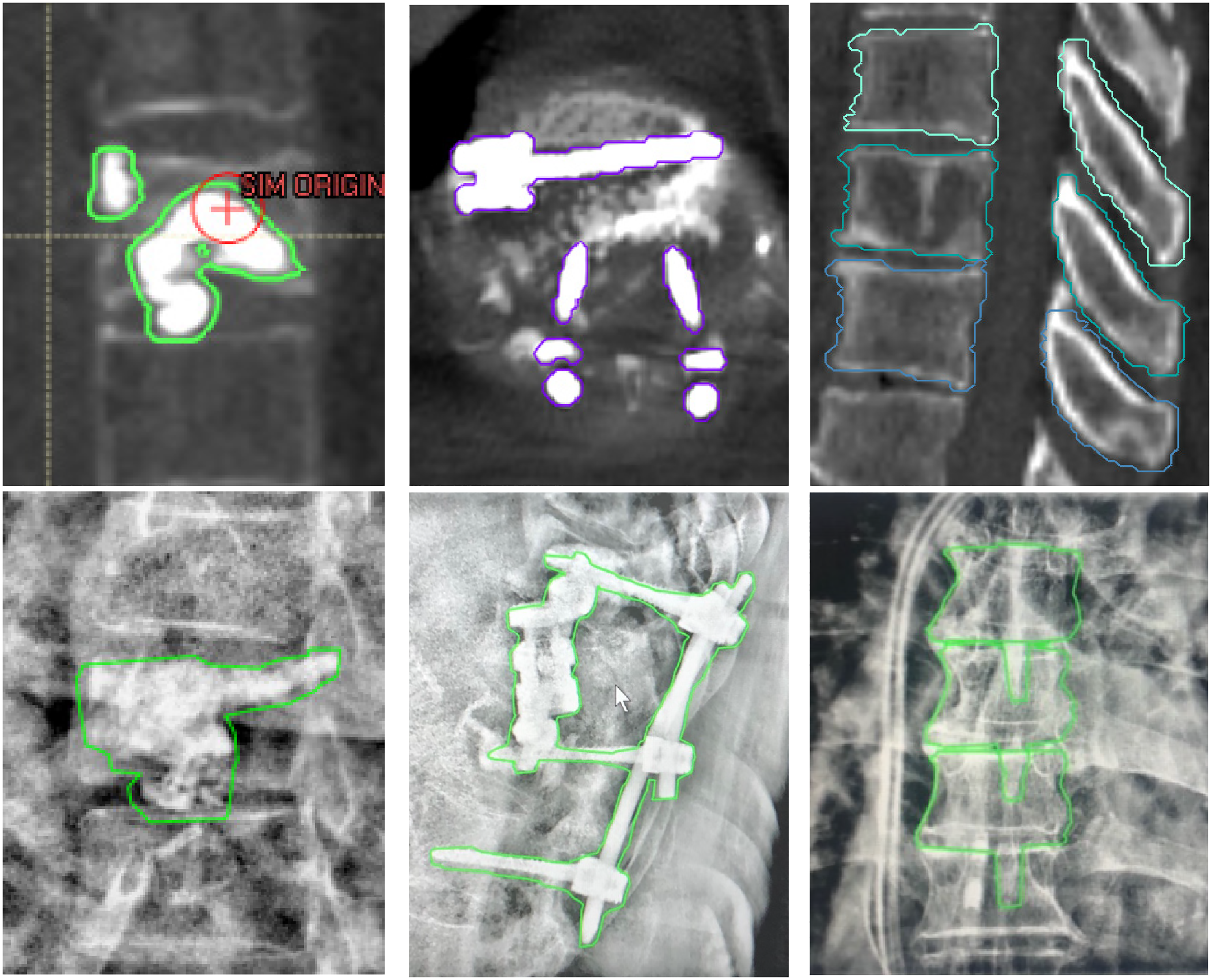
Example of the types of IGRT structures on planning CT (upper row) and projected onto triggered kV images (lower row). Bone cement (Left), orthopedic hardware implant (middle) and patient bony anatomy (vertebral body and spinous process, Right).
Treatment was delivered with a Varian Truebeam linear accelerator (v2.7), which allows acquisition of planar kV images during treatment with the OBI and triggered imaging software feature. The imaging technique (kV/mAs parameters) was modified for each patient depending on patient thickness, with a tendency to select higher kV/mAs (110 kV, 15 mAs). Among the trigger options, the time trigger was selected to acquire patient kV images every 15 s in an effort to balance temporal resolution with reasonable time for image review and decision making. To reduce scatter, OBI blades were brought closer to the IGRT structures to form a field of view with 2 to 3 mm margins. The superior-inferior margin was set to be relatively tight (1-2 mm margin) while the left-right margin was adjusted considering the rotation of IGRT structures. A content filter (local contrast enhancement using adaptive histogram equalization) was applied to the kV images.
During treatment, patient position was monitored with kV images triggered every 15 s. Upon each triggered kV image acquisition, a 2D projection of the 3D IGRT structures was automatically calculated and updated at arbitrary angles for display onto kV images (qualitative visual guide for patient alignment during treatment delivery). Alignment between projected IGRT structures and patient anatomy was evaluated. If uncertain or patient movement was suspected, beam was paused for close evaluation. While the beam was paused, kV images continued to acquire every 15 s at the same gantry angle. If clinically meaningful intrafraction motion was observed, treatment was stopped to take a CBCT and correct the patient set up.
Results
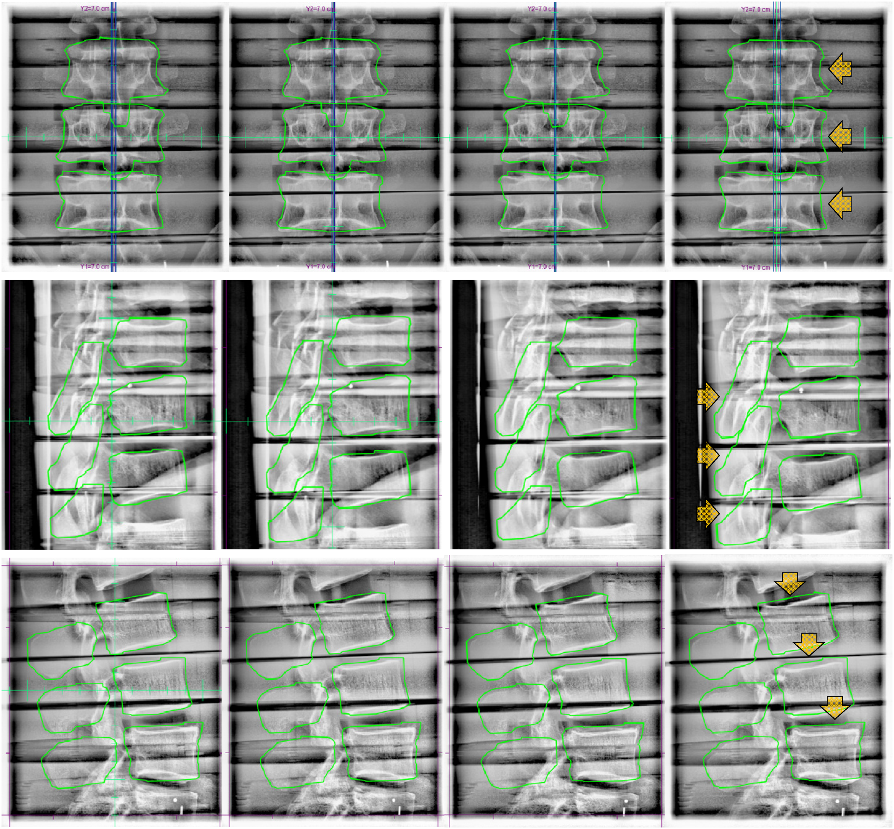
A total of 848 images were acquired from the phantom experiments. Phantom images revealed that IGRT structure precision and therefore utility of projected contour during triggered imaging improved with smaller CT slice thickness. Figure 3 demonstrates the necessity of including superior and inferior vertebra as IGRT structures in order to observe clinically relevant rotations. When pitch and yaw rotations were applied, the middle vertebra remained within the IGRT structure margin with minimal dislocation while clear dislocation was observed in the upper and lower vertebra. This result confirms that the patient movement may not be captured with triggered kV images if only the vertebra with the target is contoured as an IGRT structure, especially when the targeted vertebra is the central axis of movement. Identifying the dislocation of surrounding structures even while the target remains within the margin is important to prevent any unintended normal tissue irradiation. The highly conformal dose distribution in SBRT minimalizes the dose outside the target but cannot entirely avoid the normal tissue irradiation. Therefore, patient-specific dose distributions are calculated for each patient considering clinical information including radiotherapy history to prevent any critical impact on OARs. A treatment delivered without correcting misalignment in surrounding structures may successfully treat the target, but can cause critical normal tissue damage. While lateral or anteroposterior motion may provide the most obvious dosimetric impact (the highest dose gradients tend to be in these directions to cover disease and spare spinal cord), due to the specificity of how the fluence from each beam angle is optimized assuming consistency in material/anatomy traversed, superior-inferior motion or rotations will have unwanted dosimetric consequences as well.
From left to right, 1°,2° and 3° pitch (upper row) and yaw (lower row) rotations. When rotations were applied, clear dislocation was observed in the inferior vertebra to the right(pitch)/posterior(yaw) direction and superior vertebra to the left(pitch)/anterior(yaw) direction. However, the middle vertebra remained stationary with minimal movement.
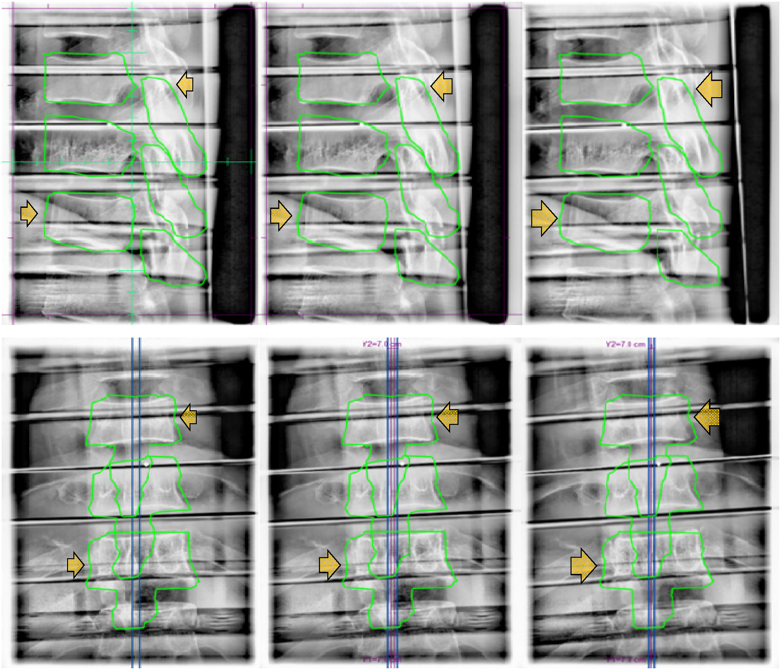
When different shift sizes were applied in x, y, and z directions, shifts smaller than 1 mm did not appear conspicuously on the kV images. The shifts bigger than 1 mm were more distinct/detectable, but it depended on the angle between the shift vector and the OBI when triggered (Figure 4). Various fractions of the shift were captured at oblique angles and the full length of the shift vector was captured at orthogonal angles. However, irrespective of the size of shifts, the shifts were not identifiable when the OBI angle was parallel to the shift direction as the shift vectors fall within the null space of the 2D image. For example, lateral shifts were not identifiable on kV images taken at 90° or 270° OBI angles, but most obvious on kV images taken at orthogonal (0° or 180°) OBI angles. This result implies that the actual dislocation of a patient could be bigger than how it appears on the triggered kV images.
Triggered kV images of L spine of the rando phantom. From left to right, 0.5 mm, 1.0 mm, 1.5 mm, and 2 mm lateral (upper row), longitudinal (middle row), and vertical (lower row) shifts were applied.
From the survey, the average time spent per decision was 7.5 s. In all shift directions, detectability was proportional to the shift size and superior detectability was observed with contours drawn using CT images with 1 mm slice thickness. Shifts smaller than 1 mm were less noticeable (12.6%) compared to 2 mm shifts (42.6%). However, as the participants were asked to decide whether a shift is needed or not, shifts smaller than 1 mm could have been noticed but not considered to be clinically meaningful enough to pause or stop the treatment delivery to make a shift. Participant detection capability was dependent on the level of training with this technique rather than their clinical duty (ie, physicist vs physician). To verify the correlation between the respondents’ proficiency in the technique and the detectability of shifts, participants were divided into subgroups consisting of those that had helped develop the procedure (n = 5) versus those that were trained but had none or limited experience using the technique clinically (n = 5). The average detectability of the experienced group for 0.5 mm, 1 mm, 1.5 mm and 2 mm shift size were 3.1 ± 6.7, 23.1 ± 19.7, 39.7 ± 22.0 and 54.2 ± 17.8%, respectively, and 10.0 ± 7.7, 14.2 ± 9.1, 18.9 ± 12.8 and 27.5 ± 14.0 for the inexperienced group. (Figure 5) Note that the “higher” detectability for 0.5 mm shifts in the inexperienced versus the experienced group may be due to the experienced group noticing the shifts but identifying that they were less than the 1 mm threshold and therefore did not require clinical correction (i.e., a lower detectability here may represent improved accuracy).
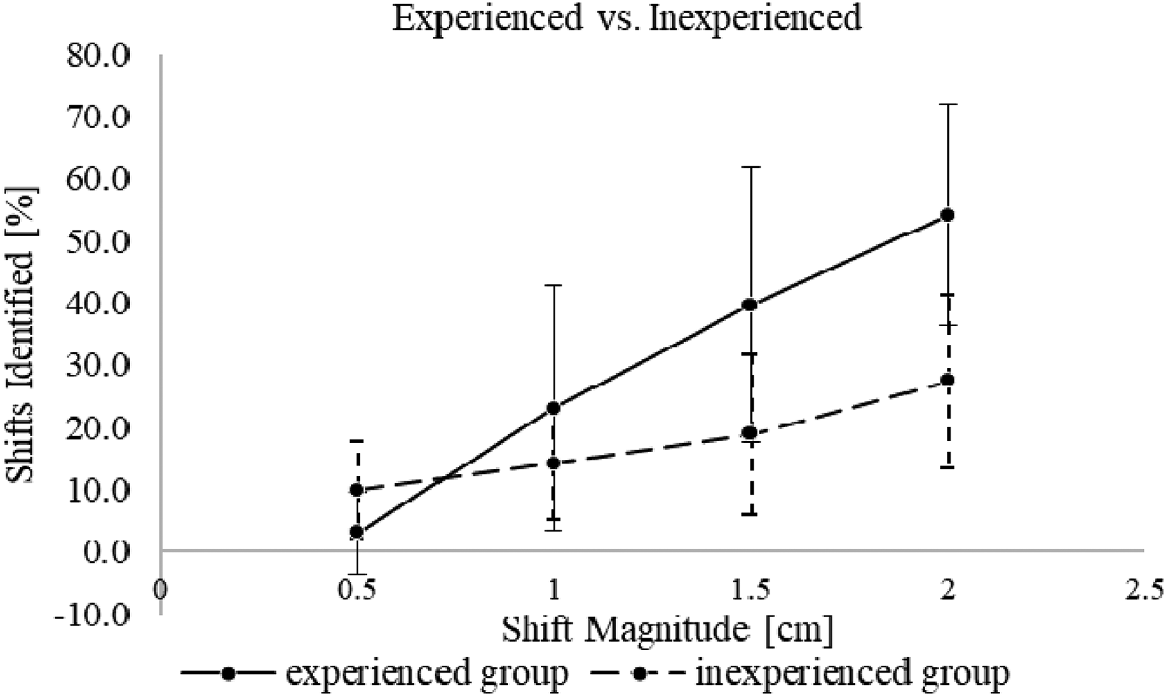
Detectability of shifts by experienced group and inexperienced group.
The robustness of our current patient immobilization systems was evaluated with our clinical implementation. Based on visual inspection of projected IGRT contours on planar kV images, an appreciable movement was detected in eleven fractions (5 patients) out of a total of 94 fractions (11.7%). (Table 1) Every shift identified during treatment was verified to be clinically relevant (>PTV/PRV margins) using CBCT to apply the correction and shift the patient. Three patients required shifts for multiple fractions. These patients were prescribed to have 5 and 2 fractions each and movement was detected during every fraction. In 4 fractions across 3 patients, multiple shifts were detected in a single fraction. The treatments were stopped to take CBCTs and correct the displacements, which otherwise would have not been detected. Treatments resumed after applying the shift.
Stratification of Data Based on Immobilization Method Used. Demonstrates that this Technique can be Used to Evaluate/Compare Immobilization Method Robustness for Spine SBRT.

Figure 6 shows the difference in contour details in triggered kV images and patient CT depending on the slice thickness. As the reconstructed vertical resolution is directly related to the CT slice thickness, contour details in IGRT structures depended on the CT slice thickness.

IGRT structures on the planning CT images (upper row) and the triggered kV images (lower row). From left to right, CT slice thicknesses are 1 mm, 2 mm, and 3 mm. Slice thickness and level of outline details are inversely related.
Discussion
The radiosensitivity of the spinal cord as one of the most critical serial organs, combined with its proximity to spine SBRT targets requiring steep dose gradients and small margins makes treatment with conventional radiotherapy techniques challenging. 24 To implement the idea of radiosurgery, Hamilton et al., fabricated an extracranial stereotactic radiosurgery frame. This approach enabled delivering highly conformal dose distribution to the treatment volume with higher precision by immobilizing patients with the frame. 25 However, this was overly cumbersome from both clinical and patient perspectives. After Ryu et al., introduced frameless image guidance in spine SBRT using an orthogonal pair of x-ray cameras, there have been many efforts to monitor patient motion, but most IGRT approaches have remained interfraction monitoring rather than intrafraction monitoring as discussed above. 26
The feasibility of the triggered imaging technique, specifically for intrafraction motion management in spine SBRT treatments, has been validated in this work, in that patient position can be monitored efficiently during treatment delivery using the OBI and patient anatomy or existing orthopedic implants without requiring specialized equipment and/or invasive/approximate tracking surrogates. In our institution, a patient movement was detected in five patients (11 fractions) out of 42 patients (94 fractions). The results in Table 1 suggest that different immobilization devices may result in less patient motion for spine SBRT treatments. This demonstrates that the presented technique can be a useful tool for a department evaluating various spine SBRT immobilization methods. Therefore, besides intrafraction motion monitoring, one of the benefits that this technique offers is potential quality assurance to verify adequate patient immobilization systems being employed. Performing such quality control within the setting of actual patient treatments provides a comprehensive examination of the limitations of various immobilization approaches. In the case where less rigid immobilization is used (eg, alternatives unavailable within a given department, patient capability to tolerate various devices, etc), this technique can give reassurance in treatment accuracy to both patients and physicians by visually providing real-time alignment status of treatment target and adjacent structures.
If patient movement is detected when an arc is almost finished, the decision to stop treatment and correct would require clinical judgement regarding the presumed effect on total delivered dose depending on the direction and size of the movement. In order to readjust the patient set up, the treatment needs to be paused to take updated images (eg, CBCT) and resumed after applying shifts to move the patient back into alignment. Due to the prolongation of treatment, there's an increased chance of patient movement. 27 Therefore, considering the risk and benefit of applying a shift would be required depending on the amount of dislocation relative to portion of remaining dose.
In the phantom experiments, some images had blurring artifacts along the air-tissue interface between the phantom slabs due to the content filter. (Figure 7) Being a locally adaptive display filter, the content filter interpolates abrupt changes in brightness into these artifacts. While these differences between the rando phantom and true human anatomy is a limitation to these experiments, this represents a close approximation that demonstrates the feasibility of the triggered imaging technique for this application.

Blurring artifacts between phantom slabs along the air-tissue interface.
Various trigger options can be used depending on the user preference and suitability for specific implementations. To evaluate the patient movement every time a certain amount of MU is delivered, the MU trigger would be suitable. However, as dose distribution is usually not uniform throughout an arc and VMAT delivery allows dose-rate/gantry-speed modulation, MU triggering may result in superfluous images acquired consecutively (either temporally or in gantry angle spacing) without providing clinically sufficient time to evaluate each image. Therefore, in terms of ensuring enough time to review each image and make a decision, time trigger provides the most consistency. On the other hand, Gantry angle trigger allows more control over which orientation images are acquired from. Therefore, the gantry angle trigger would be suitable when images from certain angles are needed (eg, in a controlled phantom experiment, such as the one presented in this work, to look at how images change with specific motion; or when patient anatomy results in certain angles providing more useful information). To observe intrafraction motion corresponding to spine SBRT margins on the order of 1 mm on the triggered kV images, the smallest available CT slice thickness (∼1 mm) is suggested for this technique. B Sintay et al. 28 suggested that reconstructed volume varies (>5% between 3 mm and 0.75 mm slice thickness) by the slice thickness. From the survey, we learned that patient shifts are more detectable with CT images with 1 mm slice thickness. (Table 2) Enhanced contour details of IGRT structures with 1 mm slice thickness provided a more precise visual guide to observers. At our institution, 1 to 1.5 mm slice thickness is usually required for spine SBRT. If scanned with >1 mm CT slice thickness, the reconstructed vertical resolution of the IGRT structures becomes larger than the SBRT margin. Triggered imaging can still be applied, however, a consult with a physician is encouraged.
Percentage of Detected Shifts According to the CT Slice Thickness (1-3 mm), Size and Direction of the Shift Vector from the Survey.

Although triggered imaging provides kV images as well as projection of expected contour locations during spine SBRT treatment, the decision to stop or continue the treatment is entirely dependent on human discretion as the software package does not offer quantitative evaluation or the ABH feature (as it might for marker tracking) in this setting. Therefore, the human factor is a critical component in this technique until algorithms are clinically implemented to detect shifts beyond a preset tolerance and activate ABH to gate the linac (artificial intelligence may prove fruitful for automatic shift detection.29-31) In spine SBRT in particular, it is critical to promptly and precisely catch fine movements to prevent a radiotherapy incident. From the survey result, we learned that training is a critical factor in increasing observer detecting capability. When dividing the participants into experienced and inexperienced groups, the difference in detectability between the two groups were 23.3% on average (1 mm CT slice thickness, 2 mm shift). The survey (or similar implementation) can serve as a training tool for potential users (therapists, physicists, physicians) to familiarize themselves prior to clinical application. From the phantom experiment, we learned that the actual patient movement can be bigger than how it appears on the images due to the nature of the 2D-based triggered imaging. The full amount of the patient movement can be detected if the direction of the patient movement is perpendicular to the OBI angle when triggered. But in most cases, a fraction of the 3D vector will be captured on 2D images at oblique angles. Therefore, training the observers will help to detect the fractions of movement of a few millimeters in size.
Depending on the precision of this approach (including user discretion), an institution may choose to use smaller PTV/PRV margins for patient treatments. Winnie Li et al. 32 suggested a 2 mm margin for the OAR and target volume. An additional consideration for the presented methodology is the fact that the reconstructed contour detail depends on the TPS and the allowed complexity in contour representation/delineation. While the difference between contours within each TPS may be subtle, accuracy in detecting shifts corresponding to SBRT margin on the order of 1 mm may be TPS dependent and this factor should be considered.
In an effort to monitor patient motion during treatment delivery, ongoing work seeks to provide more intrafraction IGRT options for spine SBRT in near future. Ren et al. introduced a limited-angle intrafraction verification (LIVE) system for radiotherapy, which combines limited angle kV-MV images with CT and verify target position in 3D. 33 Tianfang Li et al. collected continuous MV portal images during treatment and generated a series of novel enhanced synthetic treatment beam (ESTB) images for each beam and compared them with CBCT for precise detection of 2D motion in the plane perpendicular to a fixed field IMRT beam treating spine SBRT. 34 Roggen et al. used convolutional neural networks for deep learning, which allows for fast localization of the vertebrae as landmarks, to generate spine contours from kV images and compare to expected contours. 35 Along with the x-ray based IGRT, MRI-guided RT is growing in use and applications. The MR-guided RT can enable real-time motion monitoring during treatment with cine MRI and it could be an option for spine SBRT as it has been shown that these treatments are dosimetrically feasible.36-38
Overall, the presented approach using periodic triggered kV imaging and visual inspection of projected planning contours versus patient anatomy during spine SBRT treatment delivery provides an effective, non-invasive intrafraction motion monitoring solution, using the built-in functionality of the TrueBeam platform. An important limitation is that the monitoring result is qualitative and depends on observer visual detection capability. Enhanced precision and utility could be achieved if an automated quantitative evaluation feature is implemented. Future work may include developing a quantitative approach, evaluation of the dosimetric impact of shifts, and comparing immobilization approaches using this technique.
Footnotes
Abbreviation
Acknowledgements
We are grateful to have had the assistance of the exceptional team of TB3 radiation therapists at Moffitt Cancer Center in the implementation and refinement of this technique. Their tireless work is integral to ensuring that our patients receive optimal treatment.
Conflict of Interests Statement
The authors declared no potential conflicts of interest with respect to the research, authorship, and/or publication of this article.
Ethics Statement for Animal and Human Studies
Not applicable. This work does not include animal or human studies.
Ethics Statement for Animal and Human Studies
This work does not include animal studies. All human clinical data has been collected during standard of care radiotherapy and analyzed retrospectively for this work. Use of this anonymized patient data for research purposes has been approved by the Scientific Review Committee (SRC) and Internal Review Board (IRB) at Moffitt Cancer Center under research protocol MCC 17324 (“Retrospective analysis of patients with brain and spine tumors [primary and metastatic] treated with external beam radiation at MCC”).
Funding
The authors received no financial support for the research, authorship and/or publication of this article.