
Abstract
This paper focusses on finding the delamination, morphological, impact, and damping behavior of composites reinforced with graphene nanofillers (0, 0.25, 0.5 and 0.75 wt%). Different cutting settings and two distinct drill bits (TiAlN and CTiN) were utilized to assess the effect on the delamination properties. A scanning electron microscope was used to examine the drilled holes. The TiAlN drill bit showed a decrease in the delamination factor (Fd) for entrance and exit, from 1.038,296 to 1.021,103 and 1.069,418 to 1.006,036, respectively, as compared to 0 and 0.75 wt% graphene reinforcement. The TiAlN drill bit produced a mean thrust force of 28.76 N, while the CTiN drill bit produced a mean thrust force of 55.24 N. The composites demonstrated a 56.19% reduction in thrust force when compared to the TiAlN and CTiN drill bits. Furthermore, the impact energy of the composite increased with the addition of graphene, rising from 538.5 to 754.9 J/m, respectively. Additionally, the damping characteristics of the graphene-reinforced composites were investigated and found to have 6.4% higher values than those of the neat composites.
Introduction
Carbon fiber composites are the most intriguing group of materials due to their high stiffness, lightweight, and tailored properties. Hence, it finds applications in the aeronautical industry, marine, and sporting goods owing to its remarkable properties, like greater manufacturing feasibility over conventional composites.1,2 In order to provide holes for bolts, rivets, or screws in the assembly of automobile and aviation constructions, composite materials must be drilled. The selection of drilling parameters is crucial to the life of the drill bit, as that will reduce the unwanted wastage of fiber-reinforced composites through trial and error. A number of researchers3,4 have shown that the delamination of laminates and the drilling of composite materials are highly influenced by the cutting forces (thrust force) and cutting parameters (feed and speed). The increase in cutting forces, delamination, and tool wear are attributed to the inclusion of nanofiller in the composites. 5 For the drilling of composite with a helical flute solid carbide drill compared to the HSS drill, lower surface roughness values and delamination factor values were obtained due to the better dissipation of heat. 6 Modifying carbon fiber composite with carbon nanotubes (CNT) improved the flexural strength and interlaminar shear strength values due to greater interfacial adhesion and better stress transfer. 7 The ultimate strength of composites under compressive load and delamination revealed that a greater strain energy release rate is caused by displacement at the delamination zone borders. 8 The selection of material properties and the number of plies determines the thrust force value. 9 The natural frequency of the delaminated glass fiber composite increased with the number of layers but decreased with an increase in fiber angle in the cantilever boundary condition. 10 Thus, the strength of the laminate composites reinforced with fillers and proper material conditions could reduce delamination. According to Wiegand et al., 11 when a crack crosses the center of the specimen, the delamination fracture toughness of carbon fiber (CF) composites under impact loading increases.
According to Nguyen et al., 12 several fractures with delamination between neighboring plies were discovered in a curved laminate of fiber epoxy, and the cracks were located in close proximity to the inner radius of the curvature. Mei and Giurgiutiu 13 reported that multilayer delamination analysis of CF using guided wave and wavenumber analysis found that delamination occurred between the plies by analyzing the wavenumber of trapped waves in the delaminated region. Rezghi et al. 14 proposed that drilling analysis of natural fiber composites with high speed steel (HSS) drills resulted in lower delamination than core drills and also reported that coarsely structured fiber laminates lowered delamination, which was validated by using ANOVA. The delamination factor is a function of the drill diameter and feed. A small drill with a low feed rate reduces the delamination rate. 15 The larger stress in between the increased surface area is the cause of the rise in delamination that occurs with an increase in drill diameter. 16 For the delamination analysis of CF laminates, the spur drill, compared to the R950 drill, received no delamination at higher feed and speed rates, whereas a higher uncut portion was observed in the hole perimeter with the R950 drill. 17 Delamination was effectively prevented in the laminate by incorporating a backup plate where the fracture energy inside the hole was controlled by this backup plate. 18 Delamination analysis on L and T-shaped composite panels revealed that more connected delamination of the sub-laminates was produced by higher peeling stress, where the damage to the composite propagated in a transverse direction. 19 Laminates under both fatigue and static loading got similar crack migration that led to the ply splitting that ultimately gave rise to delamination, where the cracked path got weaker fracture resistance. 20 Feed rate was different at each section of laminates due to the orientation of the ply; thereby, a variable penetration rate of the drill gave rise to an inefficient material removal rate, and thereby more severe delamination occurred at the exit of the hole. 21 Using an acoustic emission approach, Kumar et al. 22 tested the drilling-induced delamination of GF laminates reinforced with 0.3 weight percent carbon nanotubes. The experiment’s findings led to the conclusion that a carbide drill coated in TiCN with a low feed rate and fast spindle speed would result in lower thrust force and delamination factor values. Bosco et al. 23 found that a higher spindle was chosen since drilling sandwich plates is only slightly affected by spindle speed, and they got a lower delamination factor at 0.03 mm/rev feed rate than 0.12 mm/rev feed rate owing to the greater force on the drill. The push-down impact of the drill chisel edge, working on the uncut layers of laminate, causes an indentation that results in delamination near the exit of the drilled hole.
Kostopoulos et al. 24 investigated the effects of adding CNT to carbon fibre composites. Adding 0.5 wt% CNT increased both damage resistance and mechanical characteristics. According to Rahman et al., 25 the impact behavior of carbon fiber composite laminates was enhanced by the addition of one weight percent oxidized carbon nanofibres. The effects of CNT on the energy absorption of a composite consisting of Kevlar fibers were investigated by Manero et al. 26 Elmarakbi et al. 27 used graphene with varying diameters (5 and 30 µm) to investigate the effects of nanomodification on hybrid composite plates. As a consequence of adding 30 µm GNPs, the absorbed energy increased, especially for 16-layer laminates, whereas peak forces and absorbed energy were negatively affected by nano-modification with 5 µm particles. Pyromellitic dianhydride and p-phenylene diamine were used by Al-Ajaj and Kareem 28 to manufacture the polyimide films via physical vapor deposition. Using polyimide and polyaniline nanofibers, Kareem 29 examined the structural, thermal, and electrical characteristics of nanocomposites. Their findings demonstrate that adding nanofibers improved the composites’ thermal stability. The dielectric characteristics and electrical conductivity of polyimide/carbon nanotubes (PI/CNT) nanocomposites at various concentrations were studied by Kareem. 30 They discovered that conductivity and dielectric constants are greatly improved by adding up to 15% of MWCNTs. The optoelectronic characteristics of PI/MWCNT nanocomposites were investigated by Rasheed and Kareem. 31 Kareem et al. 32 found that the thermal stability of PI composites increased with the addition of silica dust. Kareem and Rasheed 33 examined the electrical and thermal properties of MWCNT/carbon fibre composites. Kareem 34 examined the electrical and thermal properties of Silicon carbide/carbon fiber composites. Their findings demonstrate that increasing silicon carbide improved the thermal conductivities of the composites. The impact of phosphoric acid (H3PO4) molarity on the properties of PI/PANI nanocomposites were examined by Kareem et al. 35 They discovered that adding H3PO4 resulted in lower microhardness, flexural strength, young modulus, and glass transition temperatures. The properties of polymer nanocomposite augmented with silver nanoparticles (AgNPs) were studied by Kareem et al. 36 According to their research, adding AgNPs results in a drop in mechanical characteristics and an increase in electrical conductivity.
Nanoparticles have been found in recent studies to be capable of introducing damping to reduce vibrations in aeronautical constructions. Rezaei and Saidi 37 examined the vibration of plates composed of porous materials, paying particular attention to mechanical restrictions such as edges, geometrical dimensions, and porosity of the plate. They discovered that the porosity function had a major impact on the plate’s fundamental frequency. According to research by Saeed Amir et al., 38 raising the plate’s porosity will raise the structure’s natural frequency. The mass of the plate lowers more than the stiffness of the plate when the porosity of the plate decreases. Furthermore, when a plate is compressed uniaxially, its critical buckling stress is higher than when it is compressed biaxially. The vibration of carbon nanotube-reinforced nanocomposite plates positioned on an elastic base was examined by Wang and Shen. 39 They discovered that when CNTs were added, linear frequencies decreased and the non-linear to linear frequency ratio increased, particularly when the temperature was raised or the rigidity of the foundation was decreased. Chao et al. 40 studied the vibration and damping response of jute fiber composite sandwich panels through an analytical approach. Several research using nano filler-based composites to test mechanical behavior were found after various literature searches. Remarkably few studies on the impact characteristics of composites based on nanofillers have been documented in the literature. Therefore, it is critical to understand how the delamination, impact, and damping properties of composites are impacted by graphene filler reinforcement. A range of methods, such as heat treatment, hand layup, and sonication, are considered for the fabrication of the hybrid composite. After the composite is created, tests are run to ascertain the parameters of its delamination. A Charpy impact test is used to evaluate impact behavior. The damping behaviour of the resulting hybrid composite was also assessed using the impulse hammer test.
Experimentation
Fabrication of composites
In this work, specimens were fabricated using graphene, epoxy, hardener, and carbon fiber. To begin the manufacturing process, graphene was first mixed with acetone and then thoroughly mixed by stirring. With an ultrasonicator set to pulse on for 5 s and pulse off for 5 s, the graphene/acetone solution was dissolved in epoxy resin over the course of an hour. To get rid of the acetone, the solution was heated in the oven. After that, a matrix made of graphene and epoxy was used to strengthen 12 layers of carbon fiber. The composite was then created utilizing a vacuum bag-aided manual layup approach. The samples were called A, B, C, D, and E, respectively, and the amount of graphene was changed to 0, 0.25, 0.5, 0.75, and one weight percent. Furthermore, this prepared laminate was post-cured and then cut to suitable testing dimensions for delamination and dynamic testing. The methodology used for conducting this research is presented below in Figure 1 in the form of a flow chart. (a) Flow diagram of the methodology (b) Fabricated specimen.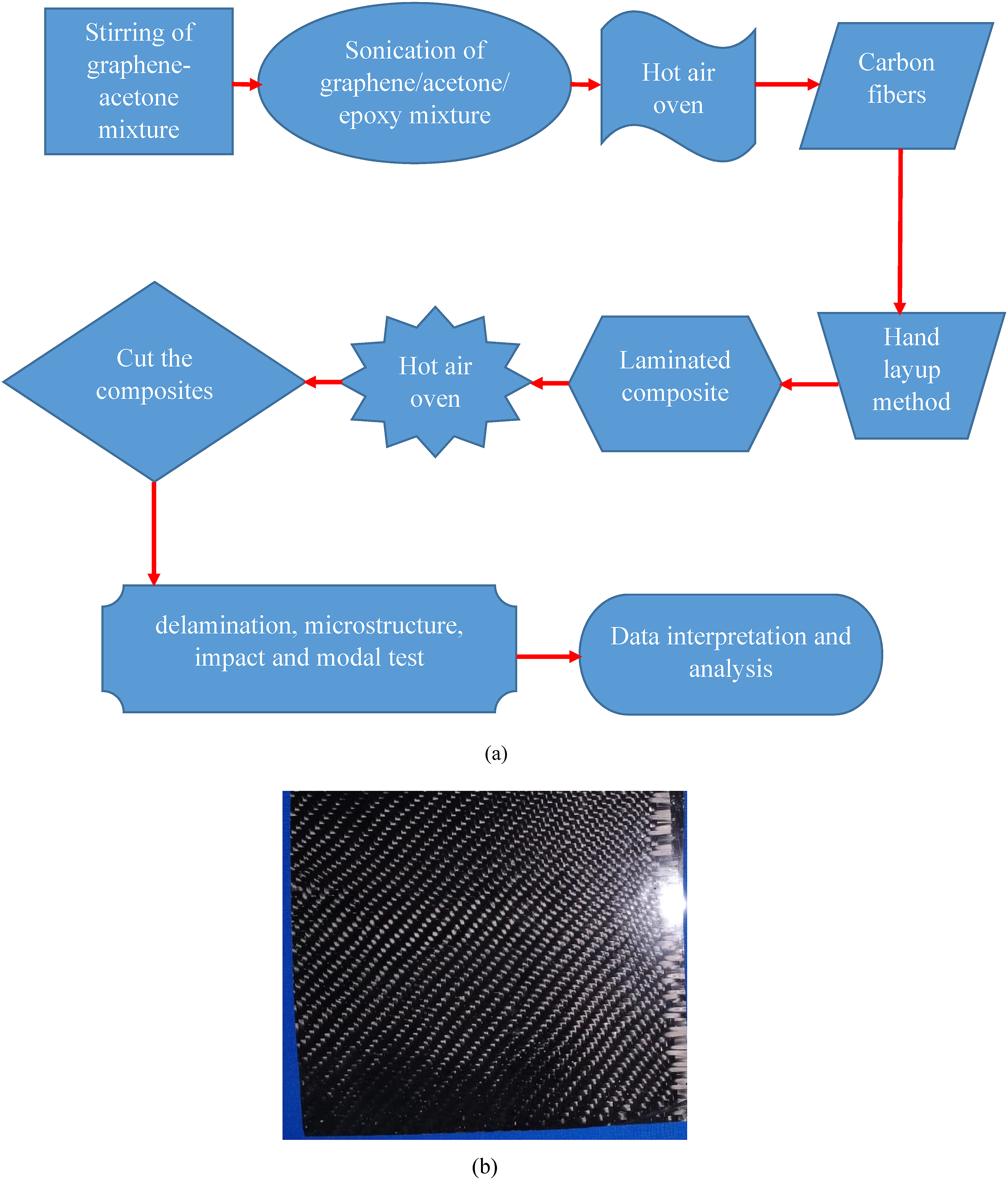
Delamination test
The most popular non-destructive method for measuring the delamination of composite layers brought on by external stresses is the delamination factor (Fd). The delamination at the hole’s entry and exit has also been described using this factor, which is defined by: Schematic representation of drilled hole parameters.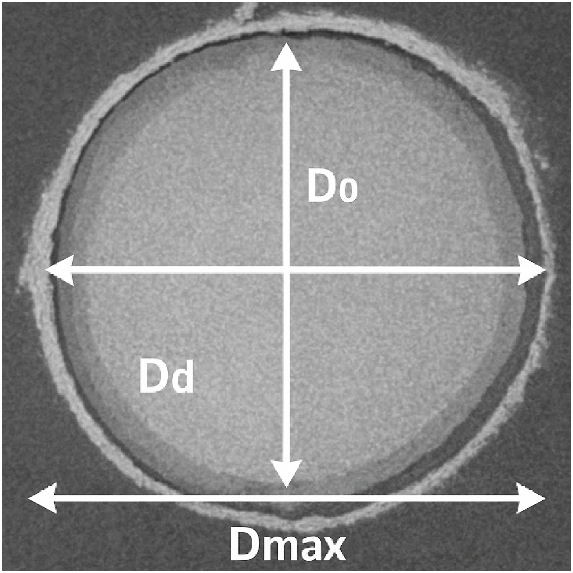

The adjusted delamination factor, introduced by Davim et al
41
accounts for the delaminated area contribution, and is defined as:

The delaminated region (Figure 2) and the areas corresponding to D0 and Dmax are denoted by A0, and Amax, respectively. This characteristic makes it possible to distinguish between two independent delamination damages that have different delaminated patches and the same maximum diameter.
As an alternative, some authors evaluated the delamination using the damage area and the quotient of the delaminated area (Ad) by the hole area (A0). 7 The equivalent Fd was recently established by Tsao et al. 42 It is defined as the hole diameter multiplied by the coefficient of an analogous delamination diameter. The delamination in the current work was evaluated using the Fd at the entry and exit.
Drill bits and specifications.


CNC drilling performed on the composite laminates.
Impact test
The impact test was conducted to find out whether the addition of graphene to laminated composites affected their impact resistance. The impact test assessed the generated composites’ impact energy and strength. A cylindrical impactor on a Zwick Roell HIT25P machine was used to dynamically load the center of the rectangular specimens (63 × 12.7 × 3 mm) by a falling weight. In order to study energy absorption, impact tests were conducted on notched specimens to find the penetration energy and highlight the unique locations for a particular energy evaluation of 5.5 J. Figure 4 displays the experimental test setup. Further, the fractured surface was inspected by scanning electron microscope (Make: Carl Zeiss, Model: EVO, magnification: 300,000x). Impact testing setup.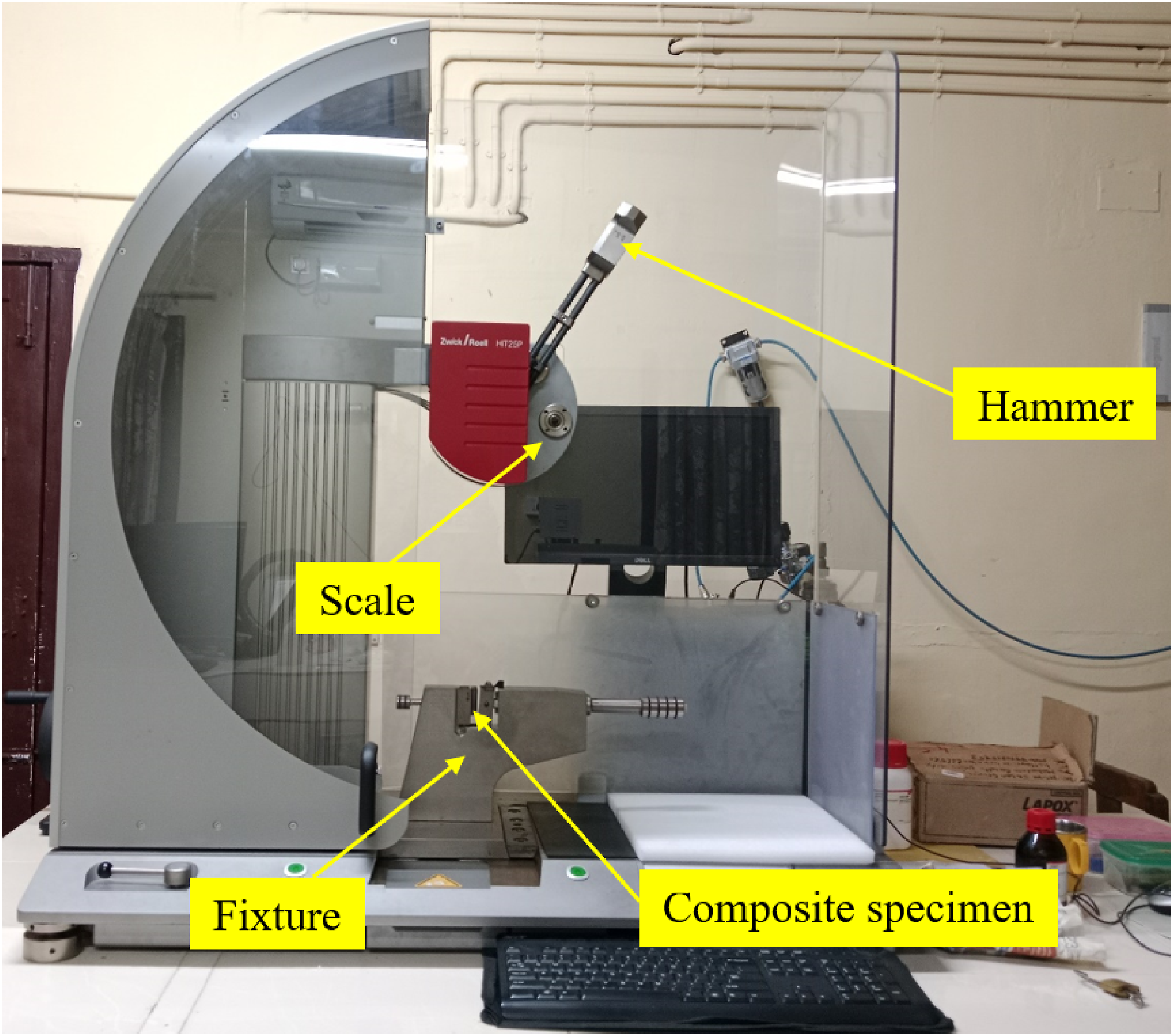
Damping test
The composite beam of 130 mm in length, 14 mm in width, and 2.5 mm in thickness is used to demonstrate the damping analysis of the graphene-reinforced composite under cantilever boundary conditions (Figure 5). The data acquisition system (DAQ) was linked to the computer system before the composite beam was set on the cantilever boundary condition. The impulse hammer and accelerometer were attached to the opposite end of the DAQ. The accelerometer, which was positioned at the top layer of the composite beam and could receive reaction signals from the stimulation, was used to measure the impact hammer’s effect on the beam. The response signal was converted into a frequency response function by means of the DAQ, as demonstrated by the Dewesoft 7.1 software display unit.
43
Experimental set up for damping test.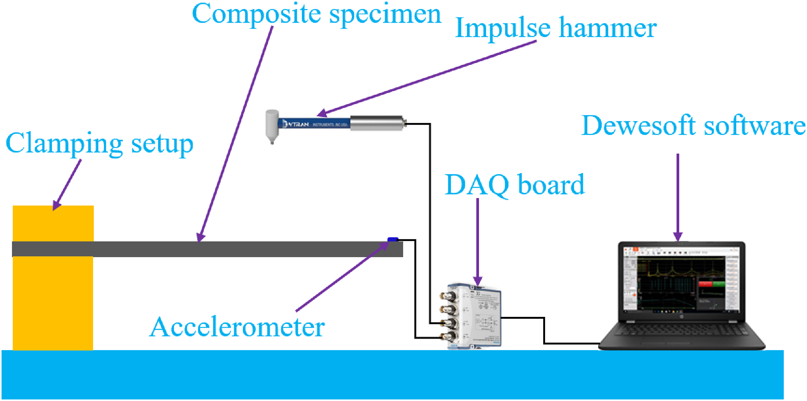
Results and discussion
The graphs shown in Figure 6 are used to study how drilling parameters affect delamination while drilling graphene reinforced composites with TiAlN and CTiN drill bits. The sample codes for various composite laminates are shown in Table 2. When drilling composites, Figure 6(a) illustrates how the TiAlN drill bit affects the delamination factor in relation to various spindle speeds and feed rates, whereas Figure 6(b) demonstrates the impact of the CTiN drill bits. The delamination factor (Fd) in composite drilling has been found to rise with a drop in drill speed. Additionally, an increase in spindle feed causes an increase in chip size, which also contributes to delamination in composite laminate drilling. The delamination factor in drilling increases with a higher feed rate. When drilling composite materials, the delamination factor rises as a result of increased contact between the workpiece hole and tool load caused by increases in drill speed and feed rate. This results in a higher delamination factor when the feed/speed ratio is 40/1500. Delamination factor versus various composite laminates under different feed and speed rates (a) TiAlN drill bit (b) CTiN drill bit. Sample code for various composite laminates.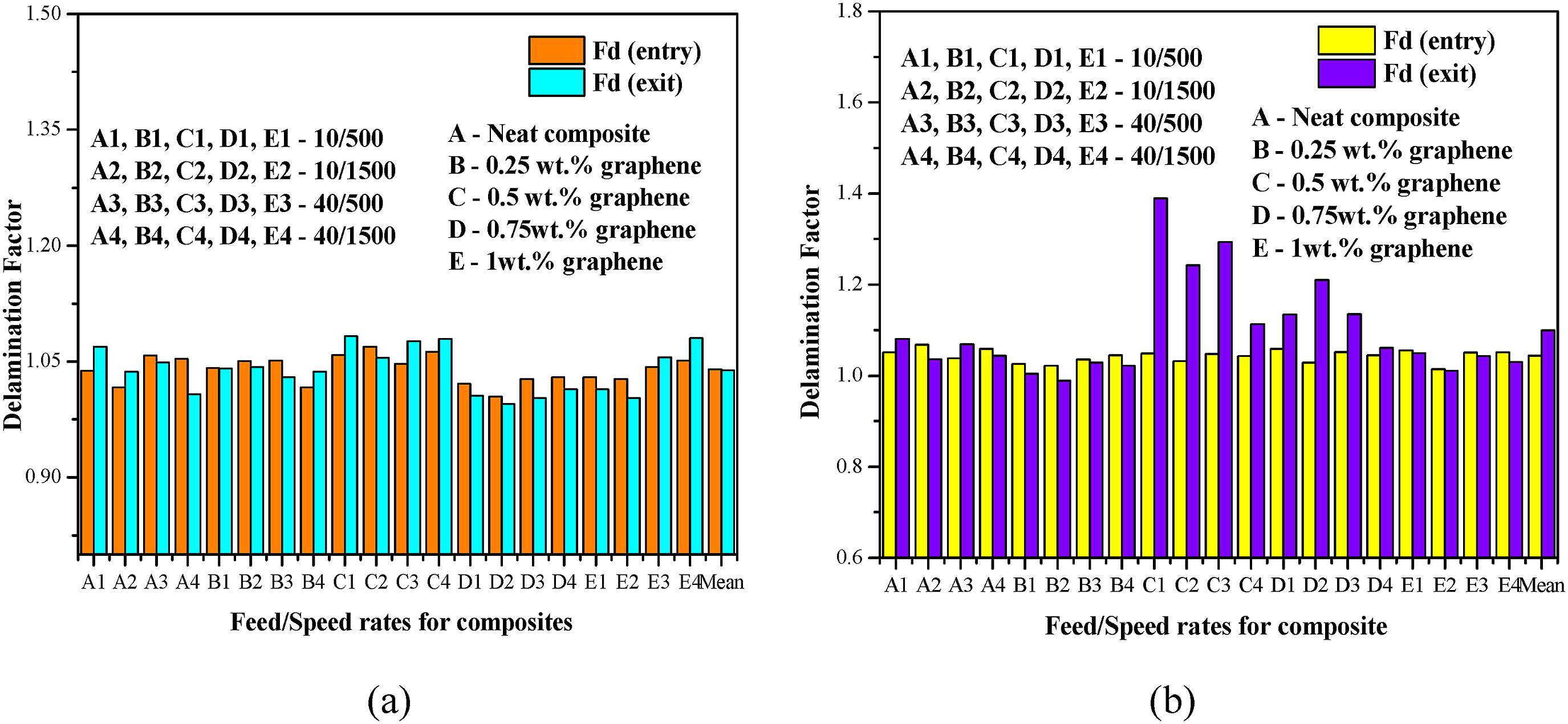

In the carbon fiber composite, the TiAlN drill bits yielded 1.039,821 and 1.038,965, respectively, for the entry and exit Fd, resulting in a mean thrust force of 28.76 N. For the entry and exit Fd, the CTiN drill bit recorded 1.046,253 and 1.048,849, respectively, with a mean thrust force of 55.244 N. Also, the delamination factor was observed to be in a higher range for the CTiN drill bit compared to the TiAlN drill bit, irrespective of filler concentration. The percentage decreases of Fd are correspondingly 0.32% and 2.63% for entry and exit for composite, respectively, when compared with the TiAlN and CTiN drill bits. The TiAlN drill bit performs better and is more suitable for drilling with less delamination than CTiN because of its higher hardness and wear resistance. Furthermore, increased heat resistance from the TiAlN coating lowers friction and permits faster cutting rates without sacrificing the accuracy of the drilled holes. The percentage decrease in the delamination factor for 0.75 wt% graphene reinforced composite is 1.66% and 5.93% for entry and exit, while comparing with neat composite without graphene reinforcement. This depicts the strong interfacial bonding between the fiber and graphene. A similar trend of decreasing the delamination factor with the addition of nanofiller is also observed in CNT reinforced with carbon fiber composite. 44 According to the findings, the incorporation of graphene reinforcement has a more substantial effect on the reduction of delamination in carbon fiber composites.
Figure 7 illustrates the thrust force experienced during the drilling process of graphene-reinforced composites and neat composites at varying feed rates and speeds. Drilling these composites appears to require more thrust force as the feed rate increases. There is a discernible correlation between thrust force and feed rate because when the feed rates are increased from 10 mm/rev to 40 mm/rev, the thrust force likewise increases from around 24.28 N to about 38.18 N. In fact, there is a strong correlation between our results and previous research in the literature reporting a similar pattern in composite drilling.
44
Furthermore, Figure 7 shows how the addition of graphene to carbon fiber composite affects the thrust force value that is obtained. The results demonstrated an increase in the thrust force from 24.28 N to 28.35 N when compared to graphene reinforcement at 0 and 0.75 wt%. Figure 7 shows that for all of the composites taken into consideration, the thrust force reduces as cutting speed increases. Several researchers have reported that when cutting speed increases, thrust force decreases.
45
The test findings show that, in comparison to neat composites, the thrust forces achieved during the drilling process of graphene-reinforced composites are much bigger under a range of feed rates or cutting speeds. Thrust force for various samples (a) feed rate 10, (b) feed rate 40.
From Figure 7, it can be seen that the CTiN drill bit obtained a higher thrust than TiAlN on composites. The increase in delamination by the drill bit is partially influenced by the thrust force, as suggested by Marques et al. 46 This observation was agreed upon in the composite for a feed rate of 40 and a spindle speed of 1500. Also, with CTiN, the delamination depicted a higher value than TiAlN for carbon fiber composites. Furthermore, the delamination was significantly reduced when operating at 1500 rpm and 10 mm/rev with a lower thrust force. Hence, this can be considered the optimum parameter for the machining operation. The decrease in thrust force is correspondingly 56.19% for carbon fiber composites, when comparing TiAlN with CTiN drill bits.
Figure 8(a) shows an SEM image of the neat composite, where the fiber appears smooth and well-aligned; however, the fiber-matrix interface exhibits signs of weak bonding, as indicated by noticeable gaps and detachment of the matrix. Figure 8(b) shows an SEM image of the graphene-reinforced composite, in which the addition of graphene improves the fiber–matrix interfacial adhesion, resulting in less fiber pull-out and more cohesive fracture. Graphene dispersion contributes to a more homogeneous microstructure, reducing the likelihood of crack initiation and delamination. SEM images (a) Neat composite (b) Graphene reinforced composite.
Figure 9(a) shows a FESEM image of the chips that were formed at a feed rate of 10 mm/rev and a speed of 1500 rpm. The chips appear larger and more continuous, with sizes ranging from ∼8.9 µm to 10.1 µm. These chip structures are consistent with low-speed, low-feed drilling, where cutting forces are lower but delamination risk can still be present. Figure 9(b) shows a FESEM image of the chips that were formed at a feed rate of 40 mm/rev and a speed of 1500 rpm. The chips appear shorter and more fragmented, with sizes ranging from ∼6.72 µm to 9.22 µm. Higher feed rates tend to generate smaller, more broken chips due to the more aggressive cutting action. These changes resulted in increased thrust force but potentially lower delamination.47,48 Adding graphene increases the stiffness, hardness, and interfacial bonding within the matrix, which makes the material more resistant to penetration and shearing during drilling. FESEM images of the chips formed in various drilling conditions (a) 10/1500 (b) 40/1500 (mm/rev)/(rpm).
Figure 10 show the drilled holes for carbon fiber composites, along with the corresponding delamination areas. It can be observed that the composite with CTiN 40/1500 yielded maximum delamination areas of 3.6, while the composite with TiAlN 40/500 yielded maximum delamination areas of 2.8. As a result, the average delaminated area for the TiAlN and CTiN drill bits is 1.4 and 2.4, respectively. The twist drill geometry enables the use of higher feed rates without delamination hazards where the front and side edges remove the chips with higher tangential and axial forces,
46
along with reduced axial and tangential force components that led to a better surface finish on the drilled holes.
49
Drilled holes on composite laminates.
Delaminated area for various composite laminates.
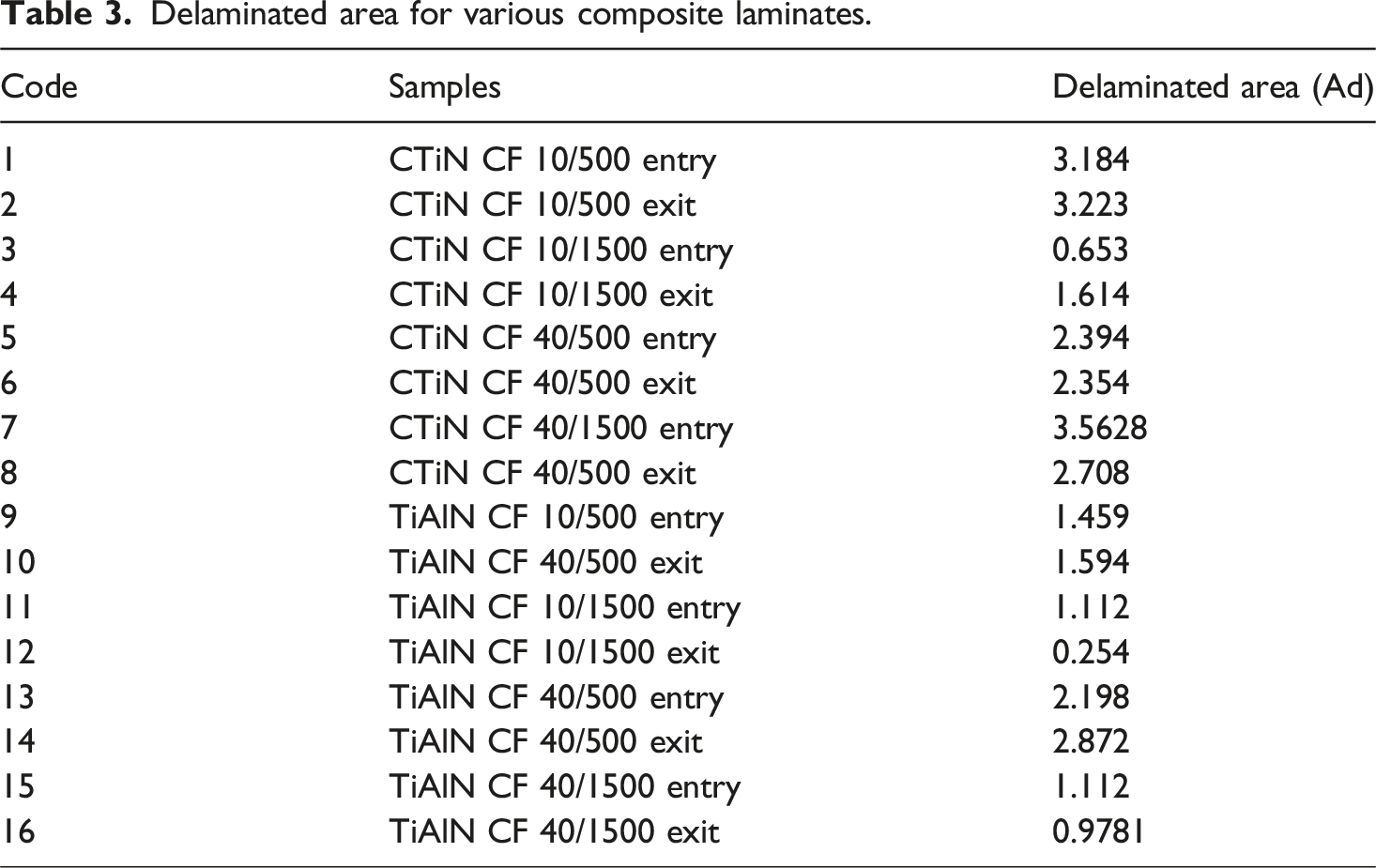
Figure 11 show the experimental results of impact energy and impact strength for all produced composites. According to the graph, D composite has the maximum impact strength at 71,221.87 J/m2. C composite has the second greatest impact energy (55,586.29 J/m2), followed by B (52,823.13 J/m2), A (50,327.92 J/m2), and E (40,183.13 J/m2). The graph also shows that composites containing graphene reinforcement have a higher impact strength than neat composites. According to Sezgin et al.,
50
composites containing carbon nanotubes (CNTs) exhibited enhanced impact strength in contrast to pristine composites. It was also observed that adding 0.5 wt% of graphene increased the composite’s impact energy and strength by approximately 7.35% and 10.45%, respectively. The addition of graphene reinforcement to the composite improves its impact strength substantially. A comparison of the damping ratios of the graphene-reinforced beam is identified experimentally, as shown in Figure 12. The damping ratio of the composites with graphene is higher than that of the neat composite beam, as evidenced by the experimental results. This might be because the significant interaction between the graphene and epoxy composite’s intermolecular polymer chains enhances the damping of the composite beams. Impact results of graphene reinforced composite samples (a) Impact energy (b) Impact strength. Damping ratios of the composite beams.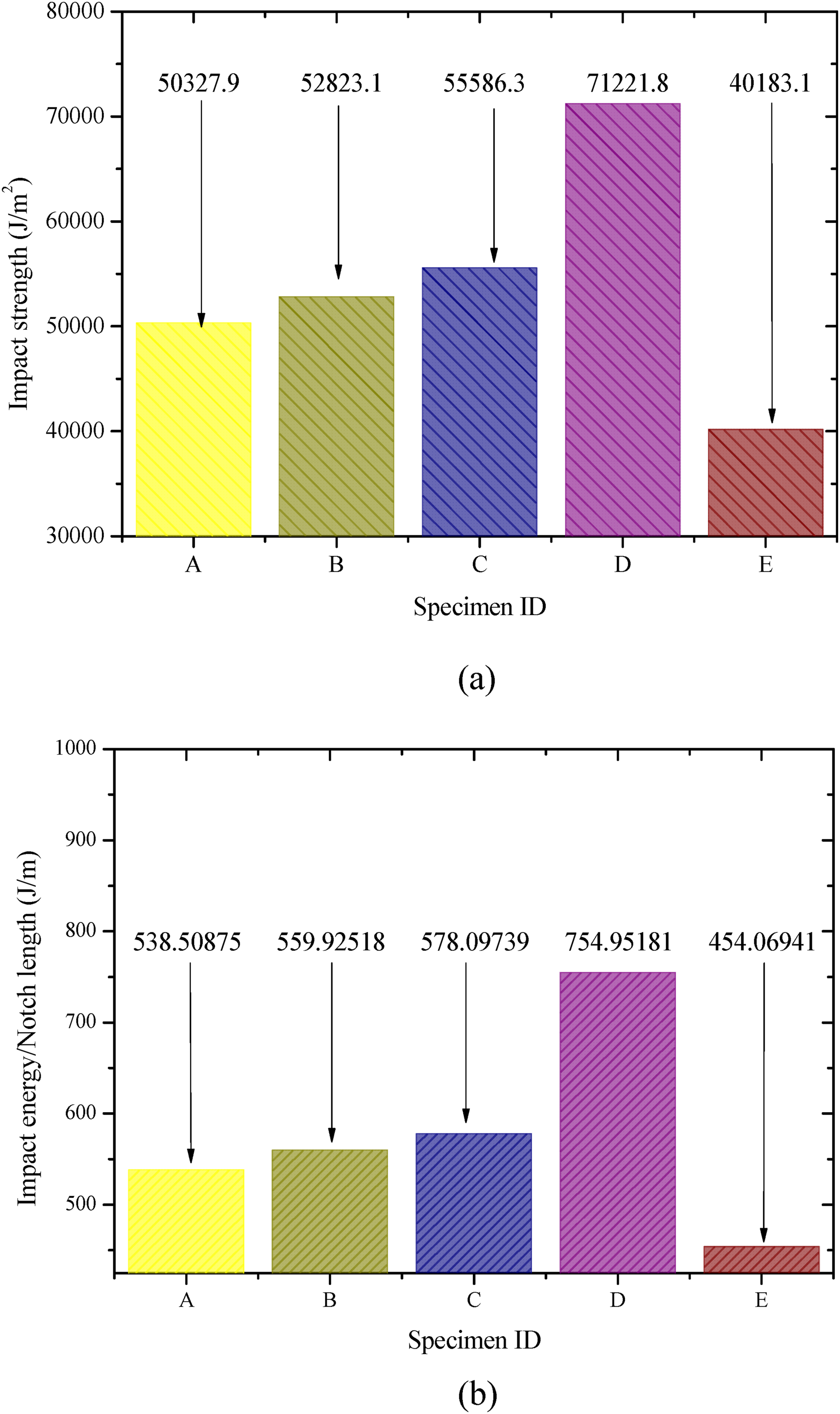

Conclusions
In this study, the delamination, impact, and damping analysis of the composites reinforced with graphene nanofillers (0, 0.25, 0.5, and 0.75 wt%) are explored. The delamination factors were determined using the effects of two different drill bits and varying cutting settings. This study also conducts impact and damping investigations to analyze the effect of graphene reinforcement. The following sums up the primary findings of this investigation: • The composite with a TiAlN drill bit exhibits a percentage decrease of delamination factor of 1.66% and 5.93% at the entry and exit, respectively, when compared to composites with 0 and 0.75 weight percent graphene reinforcement. The better interfacial bonding between the laminate plies and graphene leads to reduced delamination. • In comparison to 500 and 1500 rpm, the percentage decrease in delamination factor for the graphene-reinforced composite with the TiAlN drill bit is 1.61% and 1.09% for entrance and exit, respectively. Nevertheless, there is less delamination factor at the entry and exit sides when cutting speed is increased and graphene is added to composites. • The mean thrust force deployed for the drilling of the laminates is 28.76 and 55.24 N, and the mean entry delamination parameters are 1.039,821 and 1.046,253 for TiAlN and CTiN drill bits. According to these findings, the TiAlN drill bit outperformed the CTiN drill bit in terms of thrust force and delamination parameter. This implies that when drilling laminates, TiAlN drill bits perform better and more effectively than CTiN drill bits. • SEM images show that, in contrast to the neat composites, the graphene-reinforced composite shows a favourable response in terms of toughening mechanisms and failures. • The impact energy and strength of the composite containing 0.5 wt% graphene is 7.35% and 10.45% more than the composite without graphene.
Footnotes
Acknowledgments
The authors acknowledge the Science and Engineering Research Board (SERB), Department of Science and Technology (DST), Government of India, New Delhi, India, for providing financial support to this research work via Project No.: CRG/2022/003429.
Funding
The authors disclosed receipt of the following financial support for the research, authorship, and/or publication of this article: The authors acknowledge the Science and Engineering Research Board (SERB), Department of Science and Technology (DST), Government of India, New Delhi, India, for providing financial support to this research work via Project No.: CRG/2022/003429.
Declaration of conflicting interests
The authors declared no potential conflicts of interest with respect to the research, authorship, and/or publication of this article.
Data Availability Statement
All data that support the findings of this study are included within the article.