
Abstract
Wireless body area networks are becoming increasingly common as the use of wireless networks and other electrical devices increases. A Wearable Patch antenna is used to improve the performance of different WBAN applications. Wireless body area network (WBAN) technology is used to construct a low-profile wearable microstrip patch antenna for continuous monitoring of human vitals such as blood pressure, pulse rate, and temperature. The antenna operates in the ISM band at frequencies of 2.5 GHz, 3.5 GHz, 4.5 GHz, and 5.5 GHz. The FR4 substrate has a dielectric constant of 4.4 and is 1.6 mm thick. The proposed antenna is designed to outperform current wearable antennas in terms of reflection coefficient, VSWR, gain, and radiation pattern. The antenna has a maximum reflection coefficient of −2.72 dB and a minimum reflection coefficient of −18.78 dB, with a gain of 7.8 dB maximum and 4.2 dB minimum with a VSWR of 1.75. Other antenna field properties, such as 2D and 3D gain and radiation pattern, have been calculated. The High-Frequency Structure Simulator [HFSS] is used to design and simulate the proposed antenna. The impedance bandwidth, radiation pattern, and observed gain of the suggested small antenna for multiband operation have all been examined computationally and experimentally. The current distribution of the suggested antenna may be effectively expanded using a T-shaped antenna, and the antenna’s dimensions are considerably tailored to acquire more resonant frequencies within the needed frequency range. Compact antennas and effective multi-band radiation are both required for wireless communications. Nowadays, dual-frequency antennas are the favored option. Typically, WiMAX applications employ microstrip patch antennas, which provide circular polarization. The issues brought on by poor transmitter-to-receiver synchronization may be rectified using circularly polarized antennas. The major goal is to increase the operating bandwidth of an at its corners truncated single-feed square patch. At these frequencies, the simulation and measurement outcomes are contrasted.
Introduction
Communication technology enables us to be everywhere, at any time, and on any network. In microwave transmission, the antenna is critical. The antenna is essential in microwave transmission. It may be used to send and receive information. The main objective is to convert electricity and current from transmission lines into electromagnetic waves. On-body communication, which incorporates antennas and RF equipment into garments, is designed to minimize size and cost. Microstrip patch antennas (MSPA) are well-known for their human body immunity, long-term durability, low manufacturing costs, tiny profile configuration design, dual features, maintenance operation, and installation. At the same time, linear and circular polarization, dual frequency, agility, bandwidth, feed line, and network matching may be employed. On-body communication channels are becoming more important in medical and paramedical applications that combine sensors. As a consequence of significant advances such as increased utilization and decreased power sources, electronic components are being lowered, wearable fashion is being incorporated, and flexible equipment is being made. Wearability is a set of criteria that these electronic gadgets must meet.1–5
Antenna functions may be diminished as a consequence of antenna location due to radio wave qualities. Application measurements in the 2.45 GHz Industrial, Scientific, and Medical (ISM) band are required for any wearable. People of all ages, including athletes, the elderly, teenagers, and infants, might be tracked using wearable antennae. Hospital monitoring systems are incompatible with wearable apps. Long-term sensor use leads them to expand and absorb more noise. Further integration is necessary to overcome these restrictions. Sensors are placed in a certain location and position to collect data. Other disadvantages include interference, environmental radiation, signal denoising, and sensor relocation. Examining health parameters that may be sent to locations far away through a remote link. Researchers in a variety of sectors, including health monitoring, rescue, RFID, indoor and outdoor body centric communication, and GPS, have been more interested in body-centric wireless devices in recent years. Wearable antennas may be used in wireless communication equipment as a signal transmission and reception module in the ISM frequency bands, which run from 2.40 to 2.48 GHz and 5.725 to 5.875 GHz. The wearable antenna should be compact, tiny, light, and resistant to wear in order to maximize its utility. A wearable antenna should also be able to adjust to the user’s comfort level.6–8
Wearable antennas function within the human body by using some of the emitted energy. As a result, the antenna output falls. Textile-based antenna performance dielectric constant (r), loss tangent, and thickness (h) of the substrate materials, high conductivity of the materials, and the antenna under bending circumstances are additional important considerations for wearable antennas. The dielectric constant and thickness of the substratum, for example, influence the bandwidth and efficiency of a planar microstrip antenna. Metamaterials are constructed up of a variety of independent components created from common little materials such as metals or plastics, yet the ultimate product is typically organized in repeating patterns. Conductive Metamaterials can also help reduce absorbed strength in human body tissues by improving complete synchronization and reducing radiation from small antennas, as well as reducing the specific absorption ratio (SAR) in the cranium and monitoring electromagnetic near-fields across the antenna. We can be everywhere, at any time, and on any network thanks to modern communication technologies. The antenna is crucial in microwave transmission. It may be used for both sending and receiving data. The basic goal is to convert transmission line power and current into electromagnetic waves. With an emphasis on size reduction and cost efficiency, on-body communication, which inserts antennas and RF systems inside clothes, has been launched.
Circular polarised antennas may operate at several frequencies. The multiband circular polarised antenna may accommodate several wireless applications on a single platform and combine different frequency bands in a single antenna. Microstrip antenna may also be used in conjunction with the multiband circular antenna to produce devices that are lightweight, tiny in size, and inexpensive. Defected ground structures (DGSs) were put in place beneath the feed lines of the patch antenna by Jay et al. for circular polarisation. Reconfigurability is possible by physically altering the antenna’s radiating structure. It cannot be employed in a cognitive radio system since it has various drawbacks, such as increased antenna size and relatively slow tuning speed. The three antennas’ capacity to change their operational frequency or radiation pattern by physically moving some of their radiating components is known as frequency reconfigurability. The antennas range from a frequency-reconfigurable quadrifilar helix to a sector monopole to a patch with a reversible radiation pattern.
Microstrip patch antennas (MSPA) have several benefits, including beam scanning performance, durable design, cheap fabrication cost, small profile configuration design, dual features, and wideband not sensitive to the human body, no cavity backing, maintenance-free operation, and no installation. Linear and circular polarization, dual and triple frequency operation, frequency agility, frequency bandwidth, feed line flexibility, and matching network flexibility may all be used at the same time. It’s utilized in both planar and non-planar devices, and it’s simple to make using MMIC, which works similarly to lithography in terms of speeding up mass manufacturing. The idea is to create a flexible antenna that may be worn on the body. Sensor-enabled medical and paramedical applications are becoming more reliant on on-body communication channels. As a consequence of major developments such as increasing consumption and lower power sources, ever-evolving technology leads to a reduction in electronic components, integration with wearable fashion, and the manufacture of flexible equipment. To be wearable, these electronic gadgets must meet a number of critical criteria. Wire connections have been misunderstood as a consequence of wireless communications. Other uses, including as biological, military, and commercial, will need adaptive antennas. In order to design for wearable applications, antenna deformation is required.
The Q factor is a dimensional less number that characterizes a resonator’s bandwidth in proportion to its core frequency or shows how well a resonator or oscillator is dampened. Less energy is emitted as the patch gets closer to the ground plane, more energy is stored in the patch capacitance and inductance, and the antenna’s quality factor Q rises. The performance of the antenna after it has been twisted into a curved shape is described in this section. The most essential concern when constructing flexible antennas is that as the antenna is moved, various characteristics such as resonance frequency and radiation patterns may change. Because the resonance frequency is only displaced a little amount, E-plane bending is used. One mode is + 45° and the other is −45° at the antenna’s driving point, resulting in the requisite 90° phase shift for circular polarization. Complex arrays of patch antennas with high gain, customizable beam, return loss quality, and other unique qualities may be easily built utilizing printed circuit technologies on a dielectric substrate at low cost.
Aside from telecommunications, the ISM band may be used for Industrial, Scientific, and Medical purposes on a global scale. The ISM band operates at a frequency of 2.45 GHz. Machines like shortwave and microwave diathermy utilise radio waves in the ISM band in medical applications. To promote relaxation and healing, deep body heating is performed. Microwaves are used to heat tissue and destroy cancer cells in hyperthermia treatment. While constructing a flexible antenna, there are many important considerations to keep in mind. The operation of micro strip antennas is dependent on their substrate. When the thickness of the substrate is raised, so does the fringing. As a consequence of the fringing, the antenna’s resonance frequency may be decreased. An antenna’s return loss, gain, and bandwidth all increase significantly. Another thing to think about is the substrate material. A flexible antenna design should be used in a wearable antenna. It’s a finite element technique solution for an electromagnetic structure.
It also has a 3D analysis feature. CST and HFSS, two tools for designing wearable antennas, are often utilised. Return loss is one of the most important antenna parameters. The ratio of light reflected back from a device under test to light delivered into that device is represented as a negative value in decibels (dB). The reflection coefficient is the appropriate word for a return loss with a negative sign. The S-parameter S11 is known as return loss in two-port network theory. They will create a basic wearable antenna for smart clothes in the ISM band as part of this research. These devices, such as Bio-Signals, maintain track on patients’ vital signs. Real-time applications, such as health monitoring systems, are the most prevalent usage for wearable antennas. This paper may be used to make a basic planar antenna. HFSS might be used to make this antenna.
The return loss for this antenna is −31 dB. 2.35 GHz was the frequency range obtained. For ISM applications, this resonance frequency is appropriate. The suggested wearable antenna for health or bio-signals monitoring may also use this resonance frequency. Once the antenna has been manufactured, it may be tested using a Network Analyzer. Antenna Trainer kits may be used to test the performance of the antenna. The received power was calculated to be 86 A for a transmitted current of 120 A. It has a 70.08% overall efficiency. This wearable antenna can rapidly monitor the patient’s Bio-Signals in an emergency. The electromagnetic band gap is one of the most quickly growing fields of electromagnetic research (EBG). The ground plane’s use of an EBG structure seems to be a fantastic and appealing conductor. As a consequence, near the EBG ground plane, a beneficial electric current may form. Zhu used this strategy to develop a dual-band, body-worn antenna. The surface current of the antenna was also found to be balanced, which increased the antenna’s productivity.
Antenna design and implementation
A flexible coplanar waveguide fed flexible microstrip antenna with a floating-ground backplane is described and shown as a wearable coplanar waveguide fed flexible microstrip antenna. When installed on the high-loss human body, the antenna achieves a peak gain of 5.6 dB while maintaining proper impedance matching. The performance is then evaluated by subjecting it to a variety of bending radii and crumpling conditions. Modeling and experiments suggest that the proposed antenna’s bandwidth impedance and radiation pattern are mostly unaffected by bending and crumpling. Therefore, the suggested antenna has shown to be quite long-lasting. The suggested floating-ground backplane design also greatly reduces the planar antenna’s backward radiation, leading to a reduced specific absorption rate (SAR) and higher antenna gain. We want wearable antennas that meet the following criteria: small size; high durability; and low specific absorption rate (SAR).9–12
The antenna, one of the most fundamental components of wireless devices, has seen a dramatic uptick in demand in recent years thanks to these developments in operating systems, device size, and performance and improvement techniques for wireless systems. As mobile devices continue to shrink in size, there is a greater need for tiny, lightweight antennas that can combine with radio frequency beams. Due to the proliferation of wireless communication technologies, antennas that can function across a broad range of frequencies have become more important. Due to its small size, light weight, low manufacturing cost, and compatibility with solid-state electronics, microstrip patch antennas are considered an essential component of modern wireless communication systems.
Microstrip antennas are used in a wide variety of wireless applications owing to the widespread use of WLAN networks in recent years and the fact that these networks can transfer data at speeds of up to 54 gigabytes per second but have a maximum range of just 100 m. The three frequency bands used by the WLAN are as follows: 2.4 GHz (2.4–2.484 GHz), 5.2 GHz (5.15–5.35 GHz), and 5.8 GHz (5.7–5.728 GHz), all in accordance with the worldwide standard IEEE.802.11 (5.725–5.825 GHz).
The Global Positioning System (GPS) is a satellite-based navigation system with several applications, including positioning and navigation. Early versions of the GPS were developed with military applications in mind. Time, location, and speed are the three components needed to triangulate GPS locations. Now that it’s fully operational, GPS fulfils every expectation of a perfect locating system envisioned in the 1960s. The rapid expansion of both civil and military communications applications may be directly attributed to the production of miniaturised embedded antennas for use in navigation, mapping, and wireless communication systems. With advantages like low profile, compact size, low cost, and simple mass production via printed device technology, MSPA are favoured over other antenna types. This is because the antenna can be manufactured for both flat and irregular surfaces, making it an ideal candidate for integrated microwave circuit designs in MICs. There are, however, certain downsides to keep in mind, such as weak performance, narrow bandwidth, and poor polarisation.
The foundation of today’s communication systems is the idea that people can be connected at all times and in all places. To decrease their bulk and expense, several studies have begun looking at ways to conceal antennas and radio frequency (RF) equipment in everyday apparel. In order to serve a broad variety of biological, military, and economic purposes, antennas and electronics must collaborate. For such objectives, a large antenna that is not blocked by the human body is required. The antenna can be built quickly and easily, and it looks like a bandage that may be used on the skin. The antenna for a wearable device is often built on a flexible substrate, such as cloth. The proposed antenna properties are investigated in both flat and curved printed versions to accommodate any and all real-time applications. It has been shown that antenna performance might suffer from deformation brought on by the user’s movements. Therefore, it is very challenging to design a narrow-band antenna that can withstand body stress and maintain conformal qualities when placed close to a human body and bent. Additionally, due to the prolonged use of the wearable antenna, the SAR value should be lowered to reduce the possible adverse health effects.13–15
This textile-based antenna is intended for use in the human body and personal territory systems for short-range remote communication. The whole thing was sewn together. The aperture coupled encouraging component was included in the design, which improved data transmission over prior planar antenna designs. Normal fabric is combined with metal or polymer threads to create conductive electro-textiles. Wearable, durable, and versatile, these textiles found their way into garments. In order to properly define textile antennas, conductive materials are essential, as Ivo Locker pointed out. Losses may be reduced by using a conductive media with a low and stable electrical resistance. The antenna needed to be distorted as well, thus pliability was also a must.
The material used was a woven conductive cloth with a surface resistance of 0.05/square and a thickness of 0.125 mm. The material selection step of antenna design is critical since it dictates how powerful and suitable an antenna is for certain applications. The work in progress, which is constructed of aramid woven fabric and is suitable for flame warrior apparel, is fire resistant. The conveyor was made out of a highly conductive metalized Nylon fabric. It has a high conductivity due to its three metalized layers (NI/Cu/Ag) and a surface resistivity of 0.03/square. Apart from that, the material was flexible and corrosion-resistant, making it appropriate for use in such a severe environment. Wearable antennas should be expected to bend in a variety of directions. This is to ensure that the antenna’s performance in real-world applications, especially when it’s linked to rounded body parts like an arm, is up to standard. Multiple bending states of the antenna were used in the S11 computations. To investigate these bending qualities, an antenna was wrapped around a plastic cylinder and measured. According to the results, when bent, the resonance shifted to lower frequencies and the bandwidth shrank, regardless of the bending direction. The lower the frequency, the less the bending. While investigating the bending characteristics, the researchers identified similar estimation patterns.
One approach to get around this was to build an antenna with a broad frequency range. This ensures that the antenna will continue to work within the stated frequency range, even if the frequency changes. In his measurement report, Tanaka looked at return loss when the antenna’s H-plane and E-plane were bent. Degrees were used to distinguish the bending circumstances. The antenna was flattened at 00, and a 900 bending was seen when the H-plane was bent into a V-shape at the microstrip antenna’s bending centre. The antenna was bent into a U form using an 1800 bending machine. The E-plane of the antenna is subjected to identical bending forces. Small size, cheap cost, low profile, light weight, conformability, and simplicity of network installation are all benefits of the micro strip antenna. These characteristics are important design considerations for micro strip antennas in practical applications.
Wireless communication equipment is becoming physically smaller as a result of recent technological developments. When it comes to shrinking, the antenna’s size is unquestionably a limiting factor. One of the most significant benefits of a patch antenna in a wearable device is that it minimises back lobe radiation, which is critical in these devices. As a result, patch antennas are preferred. Patch antenna research has mostly concentrated on flexible materials as a result of the development of wearable antennas. The qualities of the materials used in antennas have a significant impact on their performance. The permittivity and thickness of the substrate, for example, have a big influence on the bandwidth and efficiency of planar antennas. Textile qualities must first be explained before they can be used in wearable antennas. Electro-textiles are conductive fabrics made from conductive metal or polymer threads mixed with traditional textiles. These materials are appropriate for wearable applications because they are wearable, robust, and flexible. To avoid losses, the conductive textile should have a low and stable electrical resistance. The materials used for the antenna must be flexible since it must deform over the fabric. For a textile or wearable antenna to be robust for a certain purpose, the substrate must be chosen carefully. The low dielectric constant of textiles minimises surface wave losses and boosts the antenna’s impedance bandwidth. There has been a lot of interest in dual band wearable communications during the last 10 years, and various alternative antenna designs have been suggested. An electromagnetic band gap substrate is used to describe the performance of a dual-band patch antenna. The antenna is comprised of common clothing fibres and operates in the 2.45 and 5 GHz wireless bands.16–20
Another dual band antenna with a denim arm structure, albeit its efficacy is limited due to return loss. Another method for achieving dual band is to load a slot antenna with two lumped variable capacitors (varactors) placed at the appropriate locations along the slot. However, it is not one that can be worn. In addition, efficiency is quite poor, and presents a psi form slotted wearable antenna probe fed MSPA for dual band. This study presents a novel antenna design that resonates at 2.5 GHz with a bandwidth of 139 MHz and at 4.87 GHz with a bandwidth of 251 MHz. However, this design does not aid us in resonating at the proper frequency. For WLAN and telemedicine applications, a dual narrow band wearable antenna operating at 2.4–2.5 GHz and 5.7–5.9 GHz is proposed. A simple modification to the rectangular patch antenna is used to achieve the suggested design. The antenna has a low-profile design. To address the issues raised above, we’re developing a dual band circular patch wearable antenna. In this dual band, the ground dimension was lowered, and a square-shaped slit was put to the patch. Four triangular cuts were made from the corners of the patch to reduce sharp angles in the current path, increasing the band width, and a rectangular slot was made in the board to add the frequency 2.4 GHz and reduce the dimensions by a few millimetres to synthesise the working frequency, all of which improved the antenna’s radiative properties.21–24
Additionally, this antenna has to have ultra wideband antenna characteristics. Although its notion was conceived in the 1950s, the microstrip antenna was first employed in space applications in the 1970s, which made them quite popular at the time. This kind of antenna is now extensively utilised in civil and commercial applications, namely in mobile devices (such as smartphones). Essentially, the MSPA is made up of three layers: The ground plane is composed of a metallic layer placed over a substrate and then another metallic layer. Different design formats, referred to as configurations, may be used for this third layer (ground plane). These are the parameters that, for example, will specify the device’s operating frequency. The most popular designs for this kind of antenna are circular and rectangular because they are simple to construct, project (for a limited number of resonance bands), and manufacture. These forms also have appealing radiation properties and little cross polarization.
Development stages of T-shaped antenna
These antennas suit both flat and non-flat surfaces well because of their low profile (very thin) design. They are also somewhat versatile because to their ease of manufacture and low cost, which is comparable to the production of printed circuit boards. Furthermore, when installed on solid surfaces, this antenna is mechanically strong. Last but not least, various antenna characteristics, including resonance frequency, polarisation, radiation pattern, and impedance, are simple to change. It proposes a hybrid antenna made up of two modules (4G antenna module and 5G antenna module). The suggested antenna is capable of working in the GSM 850/900/1800/1900, UMTS 2100, and LTE 2300/2500 bands. This research presents typical findings for this suggested antenna, including S-parameters and radiation performances. As expected, the 5G antenna module may greatly increase ergodic channel capacity when compared to a SISO (single input single output) type. A feeding strip and a 50 micro coaxial feeding line make up each 4G antenna. The protruded ground plane will, as was previously said, have decoupling effects in the higher bands and improve impedance matching in the lower bands, but it will also cause a decline in isolation in the lower bands.
A MSPA variation known as a T-shaped antenna has a radiating element or slot that is shaped like the letter “T.” This arrangement often achieves improved impedance matching, small size, and multiband operation. Both the vertical and horizontal parts of the “T” aid in stimulating various resonant modes, which may be adjusted by varying the feed position and arm lengths. Better gain and bandwidth characteristics are a result of its shape, which permits improved current dispersion. Certain strategies, including slot loading, ground plane modification, or the use of complementary split ring resonators (CSRRs), must be used to attain improved performance, such as better gain, broader bandwidth, and reduced return loss. Additionally, choosing the right materials is crucial, particularly for wearable devices where flexible, low-loss substrates are desired.
Currently, there are certain applications where antennas are used to continually track biometric information about the human body. They must always be so near to the human body in order for them to continually monitor the biometric data and transmit it to the outside world. If the antenna is firm, it cannot be maintained permanently fastened to the body. The human body won’t be harmed by an antenna composed of textile material, therefore it may be worn continuously. Health care, leisure, firefighting, and other fields will all benefit from wearable antennas. Due to the current downsizing of wireless devices, textile materials are being employed more and more for the creation of flexible wearable systems. Textiles are intriguing substrates for flexible antennas since they can be readily incorporated into clothing. The radiating patch and the ground plane of this unique sort of patch antenna are fashioned of conductive cloth. A textile material with a certain dielectric constant serves as the substrate as well. It is referred to as a textile antenna since everything is constructed of textile material. Wearable are capable of gathering data in aggregate form, but most of them are unable to evaluate it or draw any inferences from it; as a result, they are mostly employed to gather data on general health. Two kinds of materials are used in a wearable antenna: substrate and conductive. The electrical and mechanical characteristics of these materials should be carefully taken into account when designing wearable antennas.
Flexible and rigid conductive materials make up the two categories of conductive materials. Copper, silver, and aluminium are examples of stiff conductors that may be further classified into other classes. Flexible conductors include smart textile, ink, liquid, graphene (FG), graphite (FGF), carbon nanotube (CNT), and polymers. Due to their low loss, flexibility, and stretchability, polymer composites—such as PDMS-coated silica nanoparticles, polymer yarns, etc.,—are also often employed in wearable applications. Printed circuit board (PCB) and flexible substrates are two categories of substrate materials. PCBs may be further divided into a number of categories, including Roger, FR4, and Teflon, among others, while flexible substrates include textiles, paper, polymers, rubber, foam, and others. The electrical and mechanical characteristics of flexible materials may be defined in a number of ways. Due to their foldable, bending, and stretchy qualities, flexible and stretchable materials are severely needed in the age of cutting-edge and disposable electronic systems.
The development of textile-based microstrip patch antennas has increased recently due to wearable technologies, especially for use in Wireless Body Area Networks (WBANs). These antennas may be incorporated into clothes or applied straight to the skin because of their flexible, lightweight, and pleasant design. The T-shaped antenna has drawn attention among the several geometries investigated because it can enable multiband operation and provide small form factors with respectable radiation efficiency. Commonly used textile substrates include felt, denim, and polyester; they are often paired with conductive textiles like copper-plated nylon or Shieldex. The T-shaped arrangement allows for several resonance frequencies (e.g., 2.4 GHz, 5.2 GHz) within the ISM band and is very useful at improving current distribution. To increase impedance bandwidth and gain, these antennas often use design strategies including slotting, etching, or stacking. Achieving stable performance under bending, wetness, and proximity to human flesh remains challenging. Additionally, researchers are looking at fabric durability, washability, and SAR compliance. Considering all factors, textile-based T-shaped patch antennas offer a promising route towards truly wearable and conformal wireless systems that balance practicality, comfort, and safety in everyday environments.
A ground and top radiator are used by the wearable antenna. A conductive material’s conductivity, resistivity, deformability, weather resistance, tensile strength, and compatibility with flexible materials may all be assessed. The wearable antennas are made of a variety of hard conductive materials. High conductivity, cheap cost, and the ability to be integrated with textile substrates without the need of embroidery or stitching techniques are all benefits of these materials; however, their usage for flexibility is limited by their stiff structure. Wearable antennas may be made from a variety of smart textiles (e-textiles) that provide great flexibility and can be stitched into garments using fabric yarns, including Shieldit, Zelt, Flectron, Kevlar, nylon, nickel-plated, and silver-plated materials.
Design of T-shaped MSPA
Design parameters of MSPA.
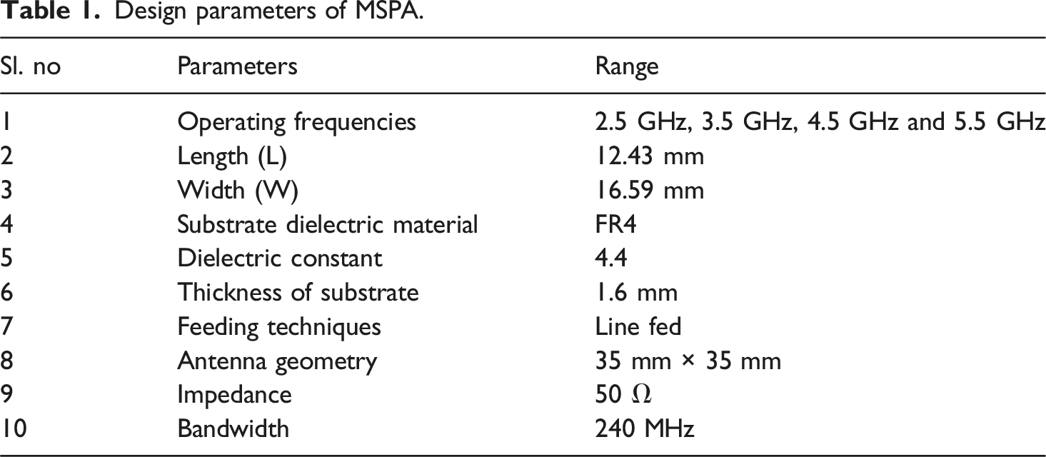
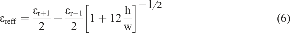
The proposed wearable patch antenna is built using the microstrip line inset feeding method. The inset feeding method is chosen because it gives the antenna a flat shape. The antenna’s working frequencies include 2.5 GHz, 3.5 GHz, 4.5 GHz, and 5.5 GHz, and it is unlicensed, thus it may be used for a number of applications. The patch antenna’s input impedance is 50 Ω. This antenna is built on a FR4 substrate with a low dielectric constant, which reduces surface wave losses. The substrate material has a dielectric constant of 4.4, a thickness of 1.6 mm, antenna dimensions of 35 mm × 35 mm, and a loss tangent of 0.02. The suggested antenna is constructed using the microstrip line feed technology. The geometrical parameters of antennas, such as patch width and length, were calculated using the equations below.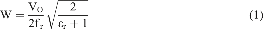
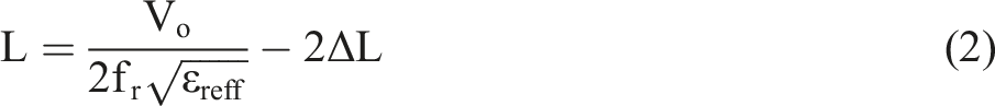
The operating frequency of a patch antenna considering L and W is given by

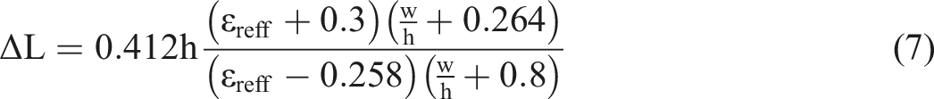
Micro-strip patch antennas are becoming increasingly common in applications that need a small footprint. These antennas are used in satellite communications, GPS, mobile phones, missile systems, and military applications. The low profile, ease of construction, cheap fabrication costs, effective radiators, and ease of integration with complex microwave circuits all contributed to the selection of these antennas. Limitations in broadband, extra radiation from feeds and connections, and surface wave radiation are all disadvantages. There are a number of options for boosting bandwidth. Figure 1 depicts a proposed design for a MSPA. Proposed structure of MSPA.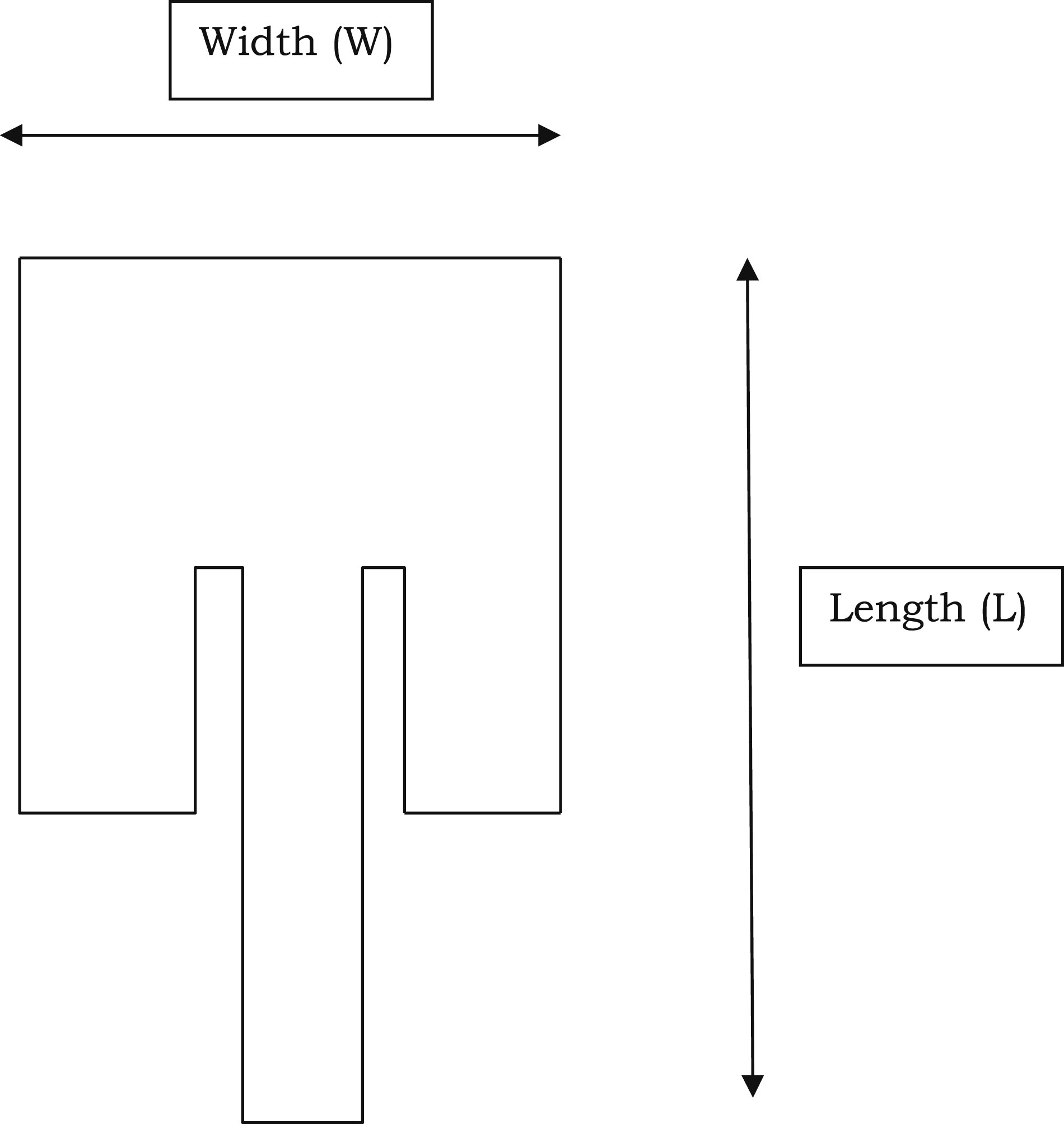
WLAN stands for wireless local area network, and it is a wireless network that links a big number of devices in a small number of areas, such as houses, offices, and other buildings. The above antenna was designed to be wearable, using a flexible substrate material that bends and folds in reaction to the wearer’s motions and can be easily hidden beneath any human clothing. Many sectors now need small, well-suited, and reasonably priced communication devices because of advances in wireless communication technology. The importance of the microstrip patch antennas in this context cannot be overstated. Depending on the operating frequency, various substrate materials and patch shapes are used to create microstrip patch antennas.
By etching the element pattern on metal trace that is adhered to a dielectric substrate material, the narrow band and broad band patch antenna is created. The substrate material’s reverse side is where the ground plane is generated. Cotton and other textile materials like jeans are utilised as the substrate for patch antennas in certain applications like telemedicine and military. Antennas should be completely incorporated into clothing when keeping textile qualities like comfort and flexibility is a concern. In this study, a wearable antenna for biomedical purposes was created employing a spiral-shaped patch over fleece as the operating material. The antenna is made flexible by the substrate material, which is fleece.
Any wireless device that is meant to function in close proximity to the human body must undergo Specific Absorption Rate (SAR) testing as a crucial safety and compliance requirement. SAR testing is even more crucial in the setting of Wireless Body Area Networks (WBANs) because antennas are often positioned close to or in direct contact with the skin. Despite showing encouraging simulated electrical performance, the suggested T-shaped wearable patch antenna ignores this crucial factor, which reduces the design’s legitimacy, safety guarantee, and regulatory compliance. SAR, which is often measured in watts per kilogram (W/kg), is the rate at which electromagnetic energy from a transmitting source is absorbed by the human body.
To protect users, regulatory agencies like the International Commission on Non-Ionizing Radiation Protection (ICNIRP) in Europe and the Federal Communications Commission (FCC) in the US have set SAR limitations. For example, ICNIRP establishes a limit of 2.0 W/kg averaged over 10 g of tissue, but the FCC requires that SAR not exceed 1.6 W/kg averaged over 1 g of tissue. Radiofrequency (RF) radiation emitted by wearable antennas, particularly those operating in the 2.4 GHz ISM bands, may be partly absorbed by bodily tissues and may result in heat consequences.
As a result, utilizing phantom models that replicate the dielectric characteristics of human flesh to conduct SAR simulations is a routine procedure in the antenna design process. Software systems like CST Microwave Studio, HFSS, or SEMCAD X employ these models to calculate the amount of radiofrequency radiation that is absorbed by the body when an antenna is positioned near to or directly on the skin. It is a serious oversight that SAR analysis was left out of the study that was presented. Although the study concentrates on radiation patterns, VSWR, gain, and reflection coefficient, none of these parameters by themselves can ensure user safety. It is crucial to balance performance and safety since systems that are tuned for high gain and efficient radiation may sometimes result in excessive SAR values. It is impossible to verify if the suggested antenna design satisfies international health and safety regulations without SAR testing. Furthermore, SAR values may affect feeding methods, antenna shape, and material selection. Artificial Magnetic Conductors (AMCs) or Electromagnetic Band Gap (EBG) constructions, for instance, may decrease SAR by reducing backward radiation toward the body.
Such features are often included because of early feedback from SAR analyses, which guides the required design changes. The authors lose out on a chance to improve the design for both performance and safety by not doing SAR simulations. Furthermore, without SAR certification, no wearable antenna may be approved by regulators or used commercially. Demonstrating SAR compliance is crucial for (like fitness tracking) or medical (like vital signs monitoring). To sum up, SAR testing is a necessary phase in the construction of any body-worn antenna, not just an optional analysis. A significant drawback that compromises the suggested antenna’s practicality and safety guarantee is the current study’s lack of SAR analysis. SAR testing must be included in future rounds of this study to guarantee that the design is safe, complies with international standards, and is functional.
The important essential element of multipath fading has an impact on how well the textile antenna performs. It happens as a consequence of human movement, which causes polarisation and shadowing to be out of alignment. To boost the performance of the textile antenna, the diversity approach is used. Different portable electronic devices in and on the human body are connected through the Wireless Body Area Network (WBAN). In order to maintain an ongoing record of patients’ health at all times, the body area network was established for medical use. The electromagnetic interaction between the wearable device and the user’s body must be taken into account while designing the antennas. The antenna’s frequency and the polarization of the incoming wave determine how the internal electromagnetic field and dispersed energy are distributed.
Future antenna research will concentrate on understanding the above-mentioned aspects when the antenna is twisted and bent, as well as improving bandwidth. When the antenna is near to the human body, researchers say it loses a lot of its functionality. A near-field between the antenna current surface and the human body impacts the antenna’s impedance matching and performance, which is especially obvious for narrow-band antennas. The usage of a framework is highly recommended. The suggested antenna should retain a consistent S11, radiation pattern, and gain even if bending deformation occurs. The antenna’s SAR value is also expected to be low. In order to achieve the required bending robustness, a planar antenna with a basic architecture was adopted in the design process. The antenna’s radiation is then shielded from the human body by a floating-ground backplane acting as a reflector immediately underneath it, resulting in a low SAR value. The fundamental benefit of this floating ground is that it maintains its structural qualities while it is twisted. As a result, bending deformation may have less of an impact on antenna performance, ensuring a low SAR value and the required bending deformation resistance.
The choice of substrate material (like FR4, cloth, or flexible plastics) and its electrical properties are explained because they directly affect the antenna’s gain, impedance bandwidth, and resonance frequency. Additionally, this area often contains simulation tools (such as HFSS and CST) for modeling electromagnetic behavior and sometimes describes manufacturing methods, particularly for textile-based or wearable designs. We address diagrams, design parameters, and performance objectives (like multiband operation or downsizing) to support the design decisions.
Results and discussion
This antenna presents the combined 4G LTE/mmWave 5G antenna design within the design restrictions of a common smartphone. The antenna systems for 4G LTE and mmWave 5G MIMO are developed independently and merged with appropriate separation. While mm Wave 5G MIMO antenna covers the 28 GHz mm Wave range, 4G MIMO antenna system covers the class 7 LTE spectrum. MIMO antenna design for 4G LTE. Additionally, the CR parameter is decreased owing to the increased distance between the CPW ground and the radiation patches, which is inconsistent with the microstrip feeding method. From planar to conformal geometry, the conformal miniaturised antenna exhibits a decrease in impedance bandwidth. This is brought on by the discontinuity that develops in the antenna when it is bent by 90°. The discrepancy between the measured and simulated data may be seen, and it may be caused by manufacturing tolerances. Additionally, the substrate’s heterogeneous dielectric constant may be the cause of the frequency shift. Due to the use of an electrically thin substrate, the suggested 4G LTE antenna’s predicted radiation efficiency ranges between 75 and 90%. Plots of realised gain and radiation efficiency are shown together. The inadequate oblique incidence absorptivity in the anechoic chamber is the cause of discrepancies between the simulated and measured findings. Strongly linearly polarised antenna is indicated by the observed cross-polarization radiation patterns in both planes being 25 dB less than co-polarization radiation patterns.
Wireless Body Area Networks (WBANs) have grown in importance, especially in healthcare applications, as the usage of wireless networks and electronic devices keeps growing. Vital indications, including body temperature, heart rate, and blood pressure, are tracked in real time by these networks. Because wearable patch antennas allow for continuous data transmission while still being small and pleasant for the user, they are essential to improving the performance and dependability of WBAN systems. In order to guarantee effective communication, low power consumption, and tiny form factors—all crucial for smooth operation in healthcare scenariosthe wearable microstrip patch antenna was created especially for WBANs. The suggested wearable patch antenna covers frequencies of 2.5 GHz, 3.5 GHz, 4.5 GHz, and 5.5 GHz and functions in the ISM (Industrial, Scientific, and Medical) band. These frequencies were chosen because they work well for wireless communications, especially in medical equipment. The antenna is built on an FR4 substrate, which has a thickness of 1.6 mm and a dielectric constant of 4.4. Because of its affordability and suitable dielectric qualities for small antenna designs, FR4 was chosen. The design of the wearable antenna seeks to achieve better radiation pattern, gain, reflection coefficient, and Voltage Standing Wave Ratio (VSWR) than traditional antennas.
The High-Frequency Structure Simulator (HFSS), a software program often used in the industry for modeling electromagnetic fields and creating high-frequency devices, was used to build and simulate the antenna. The results of the simulation demonstrated that the suggested antenna could effectively function in various frequency bands while attaining the required radiation pattern and impedance bandwidth. The measured gain and radiation patterns matched the theoretical calculations when these findings were further confirmed experimentally.
The T-shaped structure is a crucial component of the antenna design, increasing current distribution and accommodating more resonant frequencies within the intended frequency range. This capability is very crucial for multiband operation, which is a key requirement for contemporary communication systems, especially those used in WBANs. Because of its small size and ability to achieve increased bandwidth and radiation efficiency, the T-shaped antenna design is well suited for incorporation into wearable technology.
The suggested antenna is perfect for wireless communications applications, especially in WBANs, due to its small design and multi-band radiation capabilities. Continuous patient monitoring and maybe better healthcare results are made possible by wearable technology that incorporates this antenna to track vital signs and transmit data in real time to medical specialists. The antenna may handle various communication protocols, such as WiMAX and Wi-Fi, thanks to the design’s ability to function well at numerous frequencies. The antenna may be further optimized in subsequent work to get even greater performance in terms of bandwidth, gain, and directivity. Investigating the use of circularly polarized antennas could potentially improve transmitter-to-receiver synchronization, a major problem in wireless communication systems. By resolving these issues, the suggested antenna might be improved even further to satisfy the requirements of medical and next-generation wireless applications, advancing WBAN technology further.
The results from the measured and on-body simulation, on the other hand, reveal the same bandwidth with a minor difference in the amount of reflection coefficient. The discovered result showed the disparity between simulation and measurements. Because the prototype is flexible, manufacturing mistakes, SMA connector losses, cable losses, and connection repeatability with the feeding cable might all be to blame for the discrepancy in the reflection coefficient in the free space environment. The loss in the on-body simulation might also be caused by an on-body structure. Figure 2 depicts the simulated design of the proposed MSPA. Because the obtained reflection coefficient is −32.78 dB, the antenna will perform better. The ratio of the power an antenna generates to the power it receives is known as its efficiency. It’s also known as the gain of the antenna divided by the directivity of the antenna. Proposed structure of MSPA using HFSS.
Here, the flexible MSPA is supplied from the side. When compared to contact and non-contact feeding approaches, the benefits of edge feeding using a microstrip patch are limited. One benefit is that the electricity grid can be constructed more quickly. The feed network and the radiating patches will both be carved on the same board in this configuration.
Performance analysis of the MSPA
For the current design of our suggested micro-strip antenna with the needed dimensions, HFSS software is used. Impedance matching, gain, and voltage standing wave ratio are used to assess the antenna’s data transmission capability. Two characteristics of the MSPA, such as losses of the reflected signals and VSWR, enable our antenna to radiate at the needed frequency. Any effect urged to the antenna is refused since the antenna’s likelihood of loss of return signals is greater than −10 dB for the desired frequency. In this method, the return loss and VSWR requirements for a clear radiating antenna are met. The reap, which depends on the directivity of the created MSPA, is still another crucial antenna characteristic. The directivity, antenna efficiency, and other directional capabilities all affect how accurately the antenna is acquired. The pattern is the only factor used in the antenna design to regulate the directivity, which is dependent on the radiation antenna intensity.
Gain of a MSPA is constantly influenced by specific design factors like radiation coefficient and directivity. The developing materials, dielectric efficiency, and radiation efficiency will all have an impact on the radiation coefficient. For the desired frequency spectrum where our antenna is working, VSWR must be kept between 1 and 2. Additionally, one can see the difference between the two models at low frequencies, which is a problem that still requires experimental validation.
The benefits of the MSPA are its compact size, cheap cost, and low profile, as well as its light weight, conformability, and network installation ease. In practical applications, these qualities are key design considerations for micro strip antennas. As a consequence of recent technical breakthroughs, wireless communication equipment is getting physically smaller. The antenna’s size is certainly a limiting factor when it comes to downsizing. Back lobe radiation is reduced using patch antennas, which is beneficial in wearable applications. As a consequence, a patch antenna is your best bet. As a consequence of the development of wearable antennas, patch antenna research has mostly focused on flexible materials. The properties of the materials used in antennas have a big influence on how well they work. Before they may be employed in wearable antennas, textile properties must be defined. Electro-textiles are conductive fabrics made from metal or polymer combined with regular textiles. These materials are ideal for wearable situations since they are soft, robust, and flexible. To avoid losses, the conductive textile should have a constant and low electrical resistance. Flexible materials are required since the antenna must bend over the cloth. For a textile or wearable antenna to be durable for a certain application, the substrate must be carefully chosen. Textiles have a low dielectric constant, which reduces surface wave losses and increases the impedance bandwidth of the antenna.
Comparative analysis of the MSPA.

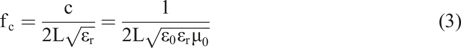
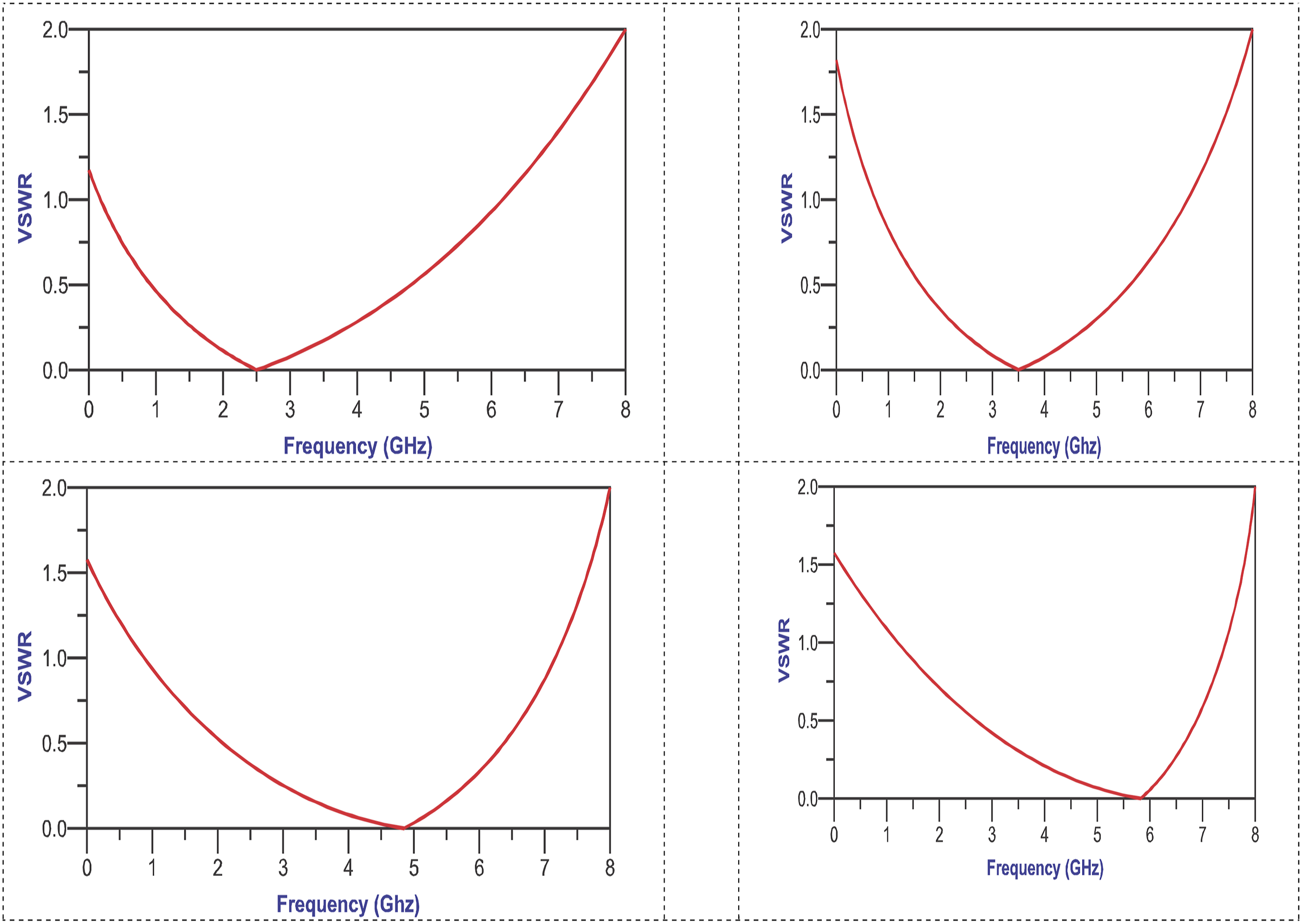
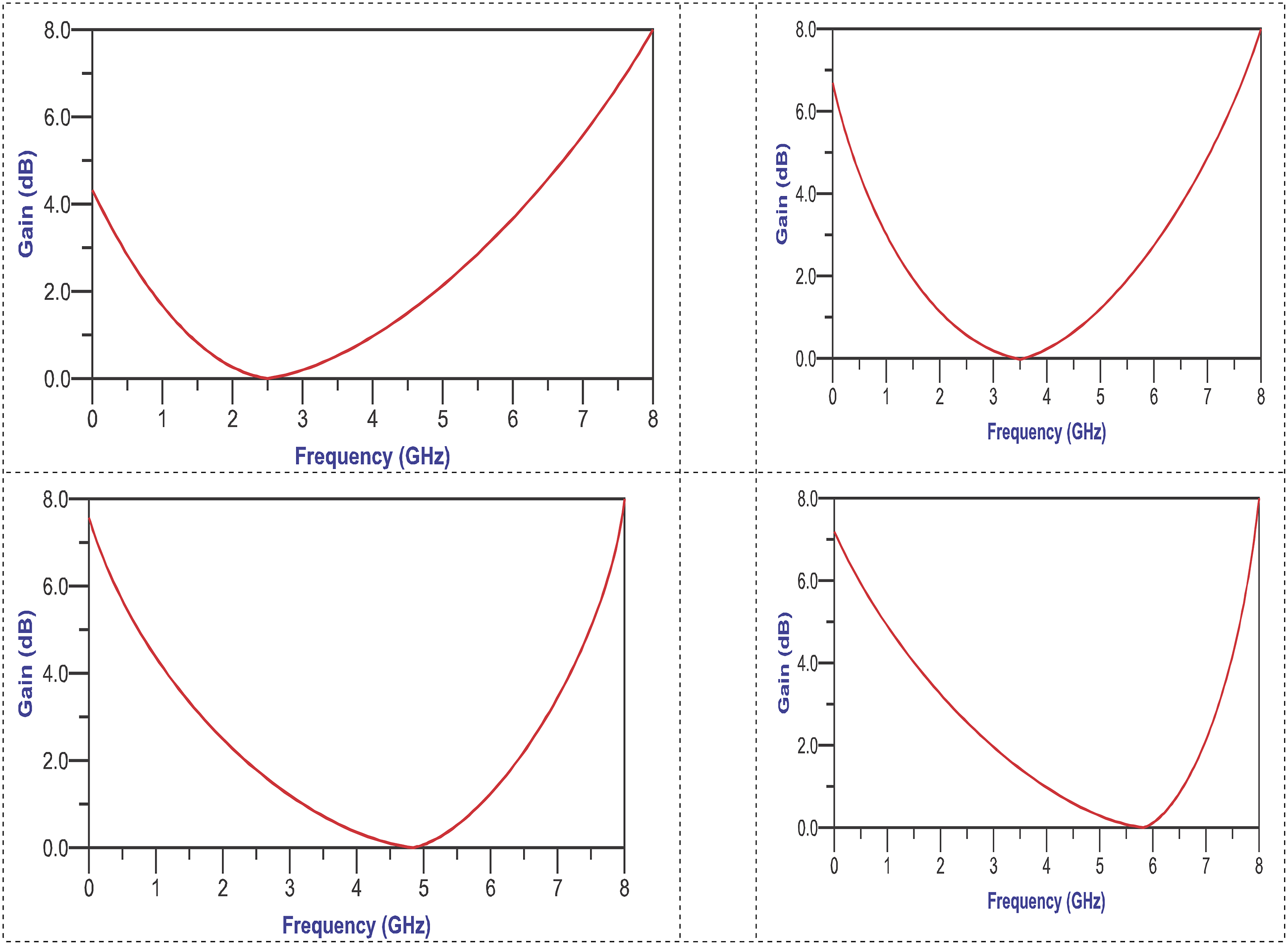
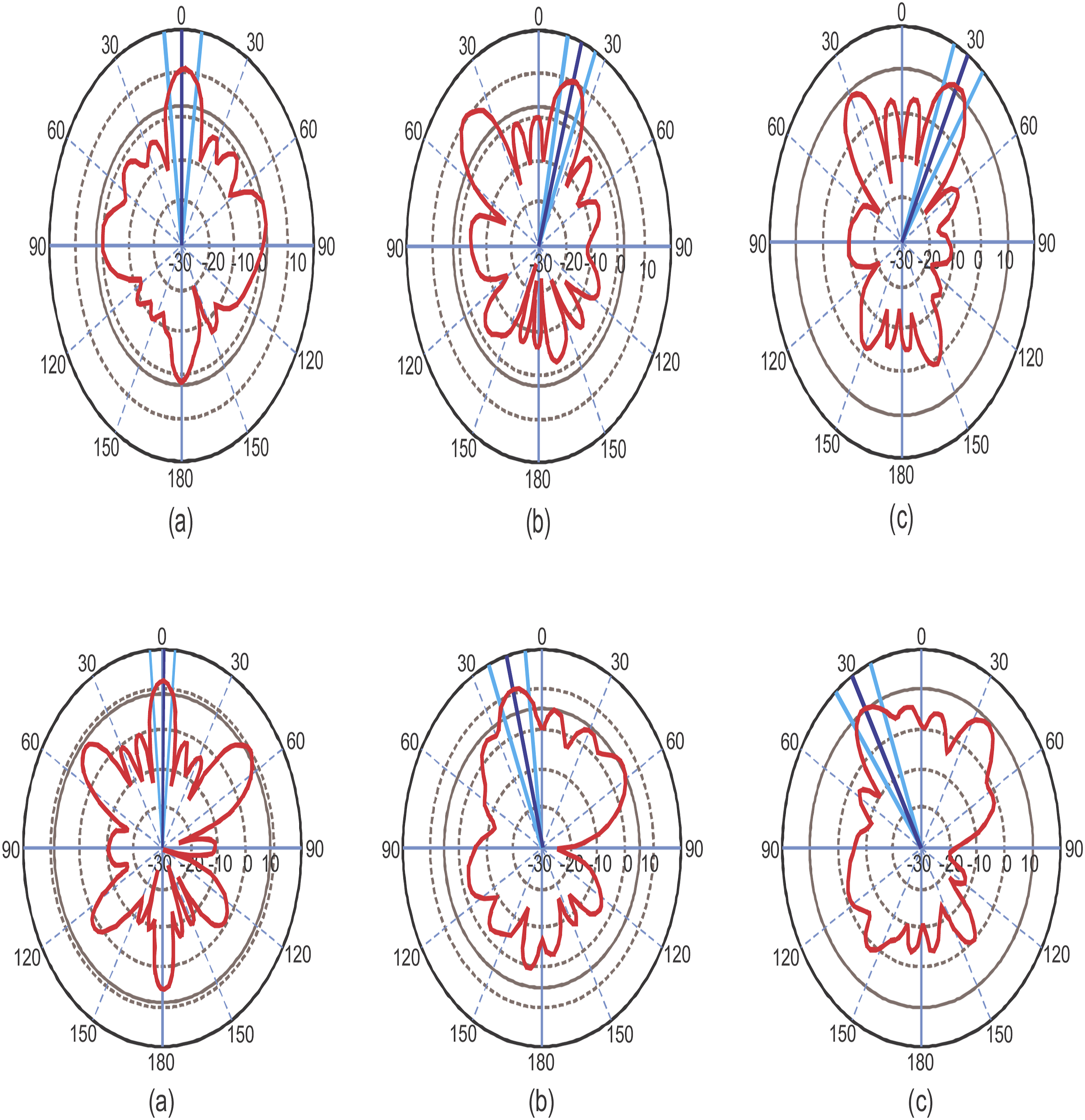
A microstrip antenna transmits and absorbs electromagnetic waves and is made up of conductive material, a dielectric substrate, and a ground plane. The ground plane and conductive material are often made of thin copper, which is a good electrical conductor. To enable air to reach the conductive substance, it is placed in the intermediate layer. The conductive material’s feeding mechanism, shape, and size (e.g., width, w, and length) all have an impact on its capacity to convert electromagnetic waves into electrical energy and vice versa. For different operating frequencies, Figure 3 shows the simulated S11 magnitude in dB for the suggested MSPA with FR4 antenna: −27.68 dB for 2.5 GHz, −18.78 dB for 3.5 GHz, −32.72 dB for 4.5 GHz, and −31.82 dB for 5.5 GHz. The simulated VSWR of the suggested MSPA for different operating frequencies is shown in Figure 4: 2.5 GHz has a frequency of 1.2, 3.5 GHz has a frequency of 1.75, 4.5 GHz has a frequency of 1.55, and 5.5 GHz has a frequency of 1.6. Figure 5 depicts the proposed MSPA simulated gain for different operating frequencies. The gain at various operating frequencies is shown in the graph: 2.5 GHz is 4.2 dB, 3.5 GHz is 6.4 dB, 4.5 GHz is 7.8 dB, and 5.5 GHz is 7.5 dB. Figure 6 illustrates the antenna’s radiation pattern. From 0 to 180°, theta values may be obtained. As can be seen, the main lobe of the antenna emits the bulk of its power toward the front, implying a high front-to-back ratio. Reflection coefficient of the proposed structure. VSWR of the proposed structure. Gain of the proposed structure. Radiation pattern of the proposed structure.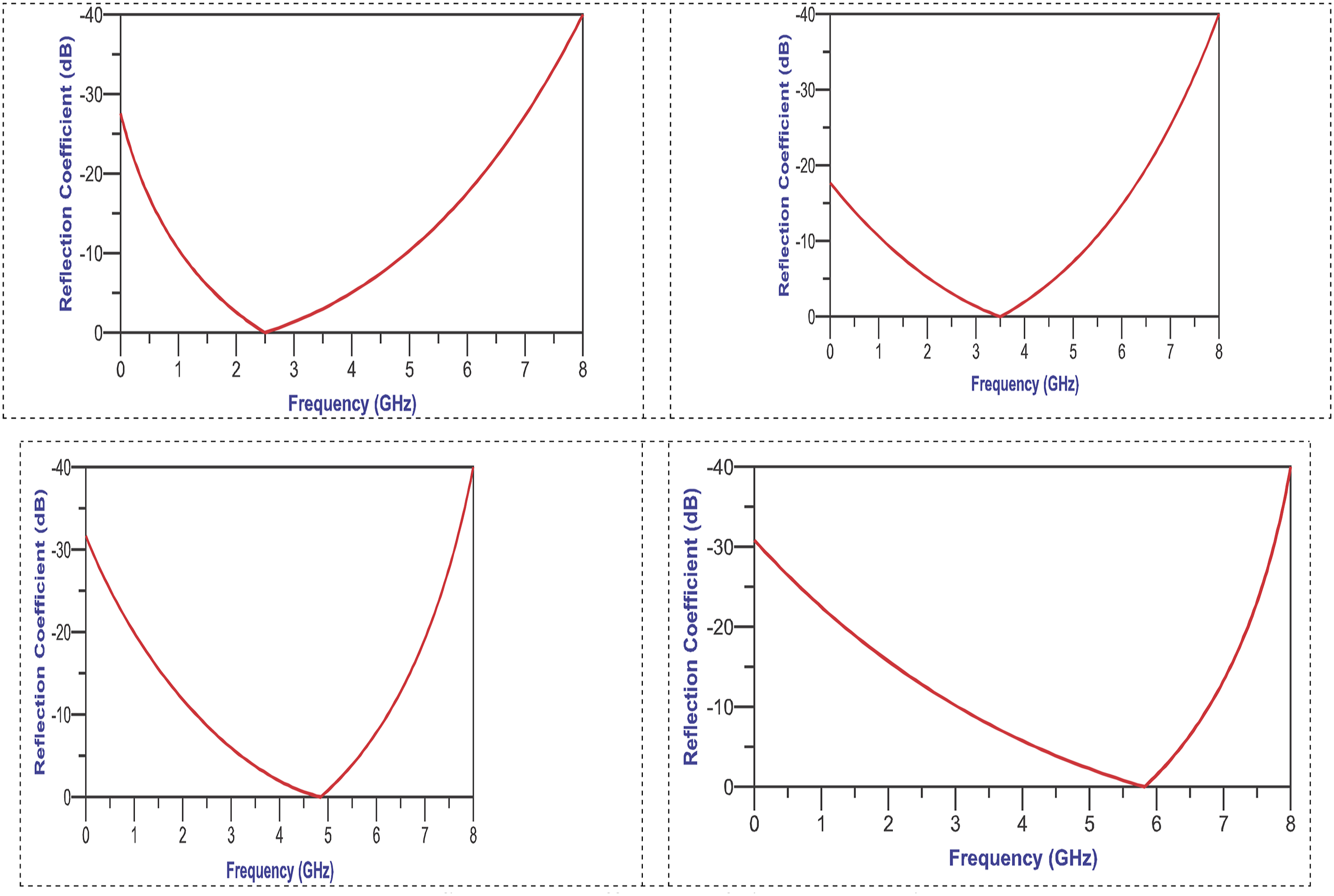
A possible way to create electronics that are part of textiles is to use a woven conductive cloth that is 0.125 mm thick and has a surface resistance of 0.05 Ω/square for making antennas. However, evaluating the material’s suitability and ensuring experimental repeatability require more than just this description. To fully comprehend the characteristics of the fabric and how they relate to the electromagnetic performance of the antenna, further details are required. The first step is to determine the kind of conductive fiber that was used in the fabric, such as stainless-steel yarns, copper-plated polyester, or silver-coated nylon. The material’s electrical and mechanical qualities are greatly influenced by the weave structure (such as plain, twill, or satin) and thread density (warp and weft per inch), which should be explicitly stated. Discussing the fabric’s homogeneous surface resistance is also crucial, especially in wearable applications where bending, stretching, and compression are frequent occurrences. Additionally, a thorough explanation of the process such as laser cutting, adhesive lamination, embroidery, or conductive ink printingused to incorporate this conductive textile into the antenna is required. In addition to conductivity, these variables may also impact long-term durability, washing resistance, and user comfort all of which are crucial for realistic WBAN applications.
The High-Frequency Structure Simulator (HFSS) was used in this work to simulate and assess the performance of the suggested wearable T-shaped microstrip patch antenna. The four ISM band frequencies that the antenna was intended to work with were 2.5 GHz, 3.5 GHz, 4.5 GHz, and 5.5 GHz. HFSS, a tool that uses the finite element method (FEM) to simulate electromagnetic fields, was used to create a model of the antenna’s shape, materials, and how it behaves in different situations. The simulation looked at important features like the reflection coefficient (S11), gain, Voltage Standing Wave Ratio (VSWR), and both 2D and 3D radiation patterns. The FR4 substrate used in the simulations had a thickness of 1.6 mm and a dielectric constant (εr) of 4.4. Standard conductive materials were used to describe the radiating patch and ground plane, and simulations considered wave port excitation and ideal boundary conditions. However, key details such as how the mesh was set up, the boundary conditions, the influence of nearby human tissue, and how bending or stretching of the fabric affects results are not completely explained in the simulation setup.
These factors are especially crucial for wearable applications. We advise incorporating mechanical flexibility analysis and body phantom models into simulation situations to enhance the reliability of future research.
By combining the newest developments in materials, technologies, and functions, next-generation textiles (NGTs) mark a paradigm change in the textile industry. The era of NGTs is being ushered in by an amazing transformation in the dynamic textile industry. The processes, challenges, current developments, and possible future prospects related to these NGTs are covered in this article. Nanotechnology, 3D printing, recycling, wearable electronics, machine learning, biomimicry, and energy harvesting are all included in this evaluation, which emphasizes sustainability, usefulness, intelligent integration, sophisticated manufacturing processes, and multifunctionality as key considerations. In addition to emphasizing consumerization, customization, safety, and protection improvements, the study underlines the exciting potential of wearable technology, smart fabrics, enhanced performance, and sustainability. Additionally, a crucial strategy for overcoming significant obstacles is covered: open innovation. This approach promotes cooperation, knowledge sharing, and the incorporation of outside resources, all of which help to address issues with mass production and scalability, costing, and the NGT industry’s deficiency of contemporary technologies.
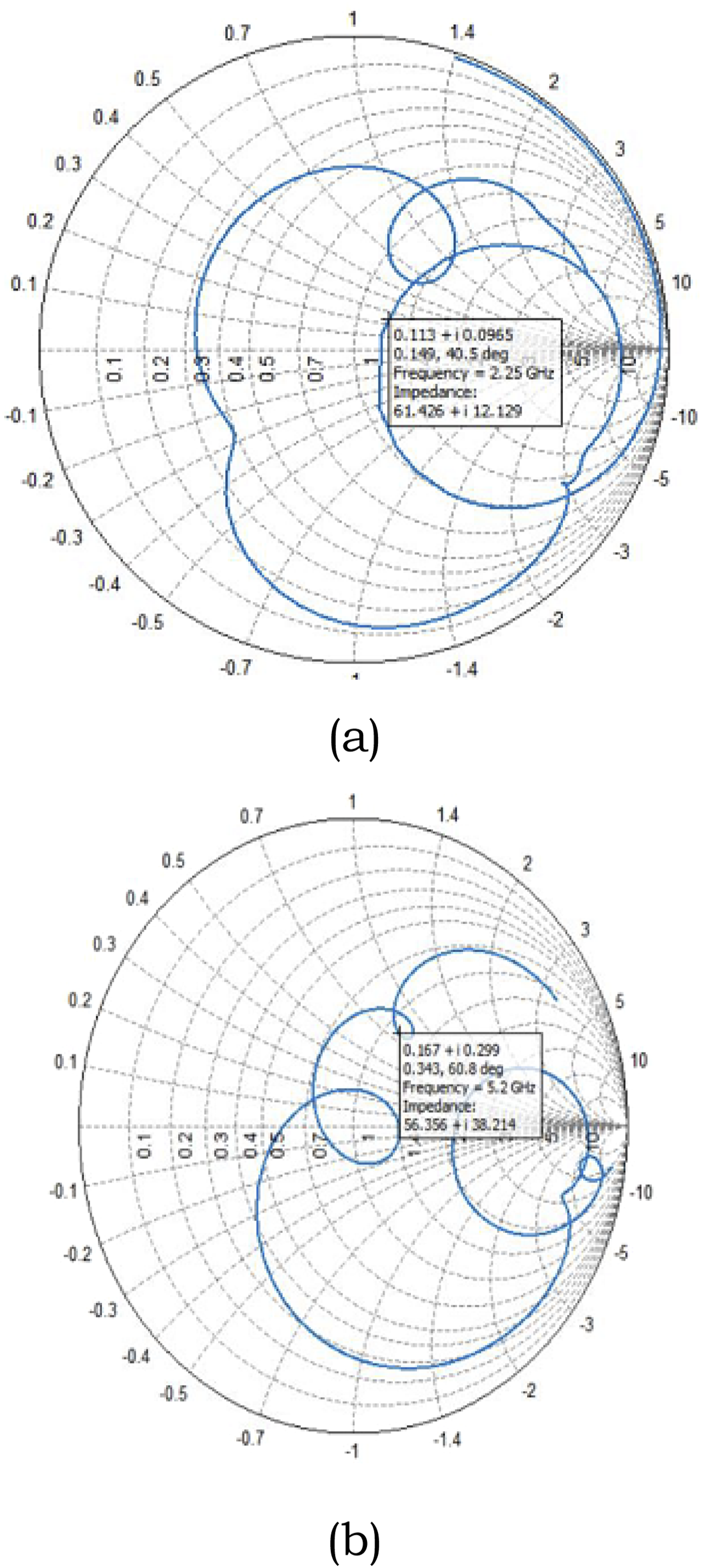
Over the whole working spectrum, the gain of the proposed antenna as determined by simulations conducted in a chamber and on a body is in excellent agreement with simulations conducted in free space. For all theta values, phi must equal 0° in order to produce the E plane radiation pattern. Similarly, for all values of theta, phi has been fixed to 90° in order to achieve the radiation pattern of the H plane. The H-plane pattern demonstrates a bidirectional radiation pattern at all of the chosen frequencies. The radiation is unidirectional in the E-plane. It is seen that the vacant area in both planes is properly matched. Simulations of the body and measurements of patterns at specified frequency. Over the whole working spectrum, the gains of the proposed antenna as determined by simulations conducted in a chamber and on a body are in excellent agreement with simulations conducted in free space is shown in Figure 7. The smith chart of the proposed antenna is shown in Figure 8. On body and off body of wearable devices. Smith chart of the proposed antenna. (a) E-Field of the Proposed Antenna, (b) H-Field of the Proposed Antenna.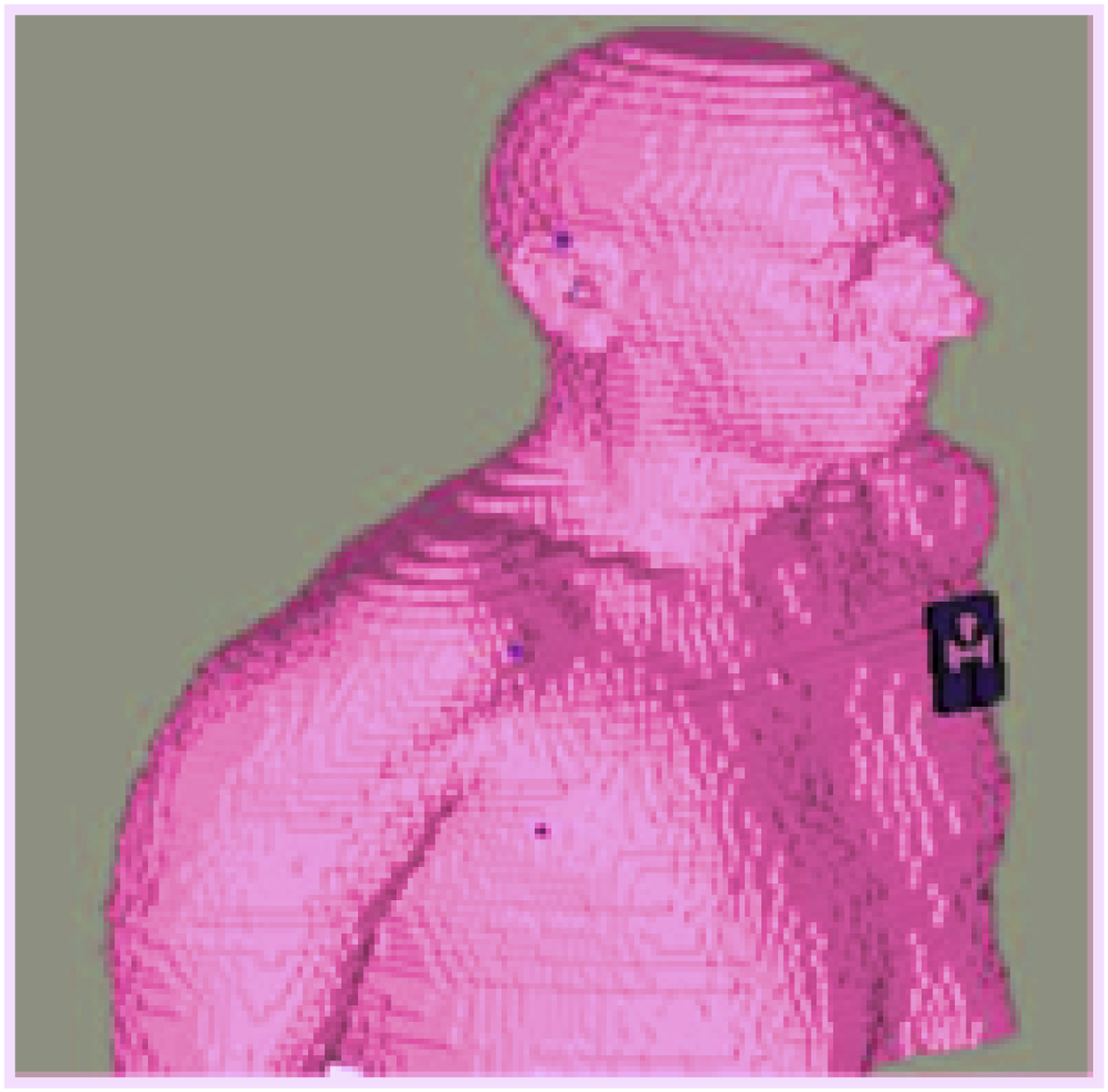
An understanding of the antenna’s distinctive T-shaped layout and how this design facilitates multiband operation may be gained from the first set of pictures, which most likely display the antenna geometry and simulation results. For instance, the S11 figure shows the reflection coefficient at various frequencies, showing how well the antenna matches each band. The simulated radiation patterns and gain plots show how well the antenna sends out signals and in which directions, which is important for determining if the antenna can be used effectively in real-life situations. These simulations are essential because they support the antenna design’s theoretical performance, which supports the decision to use it in wearable applications. Figures showing the manufacturing process and testing equipment are essential for verifying that the suggested antenna can be used in practice, in addition to design and simulation findings. They demonstrate the practical implementation and testing of the antenna in real-world scenarios, such as placing it on a human body or phantom model to assess performance. The enhancements achieved in the suggested design are further shown by figures that contrast the antenna’s performance with those of previous designs (e.g., in terms of gain, reflection coefficient, and VSWR). Incorporating SAR analysis statistics would be essential for proving the antenna’s safety when utilized near human tissue and guaranteeing that it satisfies legal requirements. When taken as a whole, these numbers provide a thorough grasp of the antenna’s construction, operation, and practicality.
Stubs, DGS, and an elliptical-shaped aperture outside the radiating patch increase the antenna bandwidth. The antenna is built with dimensions that allow it to fit into any small, contemporary Smartphone. Depending on the inductive impact of the DGS structure, the slot in the ground plane disrupts the current distribution and changes the resonance frequency. By tweaking various structures, a certain resonance may be attained since this alters how electromagnetic waves propagate through antenna substrate layers. If the resonance is near to the antenna’s operational band, it may also result in an increased bandwidth; otherwise, multiband antenna may be produced. The parasitic element’s slots, which are indirectly connected with the antenna patch and stubs on the sectored patch antenna, are employed in this situation to boost the bandwidth. The goal is to disrupt the current distribution on the stubs of a radiating patch that is indirectly connected with the DGS ring slot by adding an inverted T-shaped metallic patch surrounding sectored radiators, which dramatically enhanced the bandwidth of each band. The slot width, ring diameter, split ring percentage, and slot placement are some of the design elements that determine the antenna impedance characteristics. To determine the antenna dimensions, a parametric analysis of the design parameters was carried out at this stage of the modelling process. The ground’s centre was optimised, and two bracket-ring holes were cut out at the same distance in opposing directions is shown in Figure 9. Because of its low number of minor lobes, the antenna is also suitable for wearable applications. Current distribution of the T-shaped structure.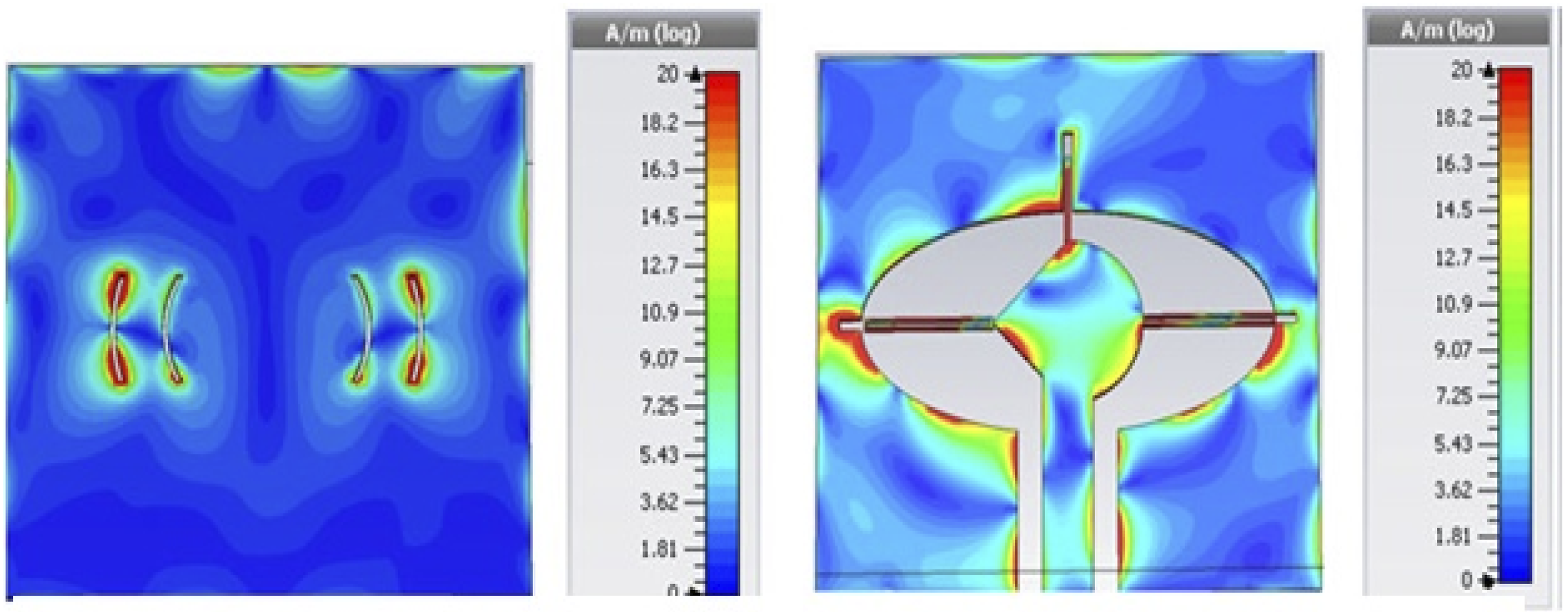
Comparative metrics analysis of the MSPA
The Comparative analysis of the MSPA is shown in Table 2. Gain, VSWR, return loss, radiation efficiency, radiation pattern, reflection coefficient, and other parameters are used to evaluate the antenna’s performance is shown in Figure 10. These characteristics are used to objectively evaluate antennas and determine their suitability for a given application. The scattering(s) parameters are used to analyze the return loss. The loss of signal power produced by reflection induced by incorrect antenna-to-feed-line matching is known as return loss. A high VSWR means that the rate of return loss is larger. It’s also a measurement of the load’s mismatch with the transmission line. The VSWR (Voltage Standing Wave Ratio) is often used to calculate the Standing Wave Ratio. The standing wave ratio is calculated as follows: The VSWR is calculated using the formula VSWR = Vmax/Vmin. Parameter analysis of microstrip patch antenna.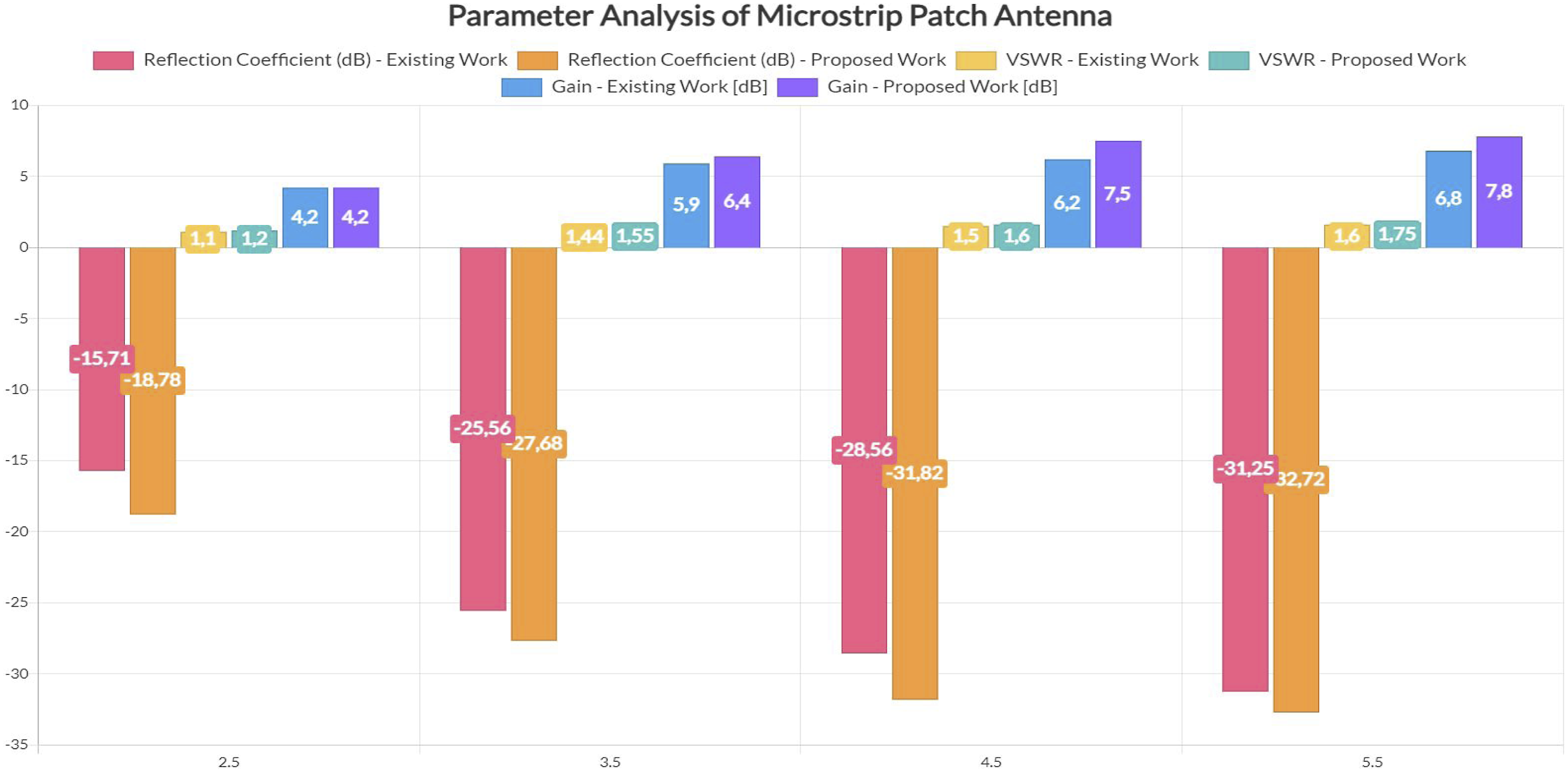
The VSWR is always +1, and it can never be higher than 2. In both cases, the VSWR is judged to be less than 2. The ratio of the power emitted from a far field source on the antenna beam axis to the power generated by a hypothetical lossless isotropic antenna is the antenna gain. With coaxial feed, gain performance is increased. The typical impedance value, which corresponds to a 50 Ω resistance, is found to be extremely near to 1. As can be seen from this value, proper matching occurs, resulting in adequate transmission. The antenna will be vulnerable to physical stress and collisions since it will be mounted to the outside layer of a person’s clothes. Torsion and bending, on the one hand, and shock impacts, on the other, were the two principal forms of physical impacts investigated. While shock hits, including those to the antenna, are often perpendicular to the body surface, the antenna’s relatively flat surface will adjust and stay uninjured.
The antenna must revert to its previous form after a collision. As a first step toward flexible and resilient implementations, some packaging choices are also offered. By simply adding arms to cover more frequency bands, the antenna may be enlarged to a certain extent. Only a few conductive structures fulfill this condition, and owing to its cheap cost, great flexibility, and ease of manufacture, a very thin copper thread was employed in this case. For low-cost demonstration reasons, the antenna was enclosed in a flexible silicone dielectric substrate, as specified in a much thicker mould layer. This paper presents preliminary findings on the modeling and fabrication of tiny multi-band antennas in the presence of a human body and without the need of a ground plane.
Designing and developing a wearable microstrip patch antenna for Wireless Body Area Networks (WBANs) is the main goal of the research that is being presented. The antenna uses an FR4 substrate with a dielectric constant of 4.4 and a thickness of 1.6 mm, and it works in the ISM band, which includes frequencies of 2.5 GHz, 3.5 GHz, 4.5 GHz, and 5.5 GHz. When the antenna’s performance is compared to that of other wearable antennas, it demonstrates improvements in important characteristics such as radiation pattern, gain, VSWR, and reflection coefficient. Notably, the gain varies from 4.2 dB to 7.8 dB, the highest reflection coefficient is −32.72 dB, and the VSWR is 1.75. All of these characteristics show excellent power transmission and efficiency performance. The antenna’s small and dependable form makes it ideal for incorporation into clothing for Internet of Things applications. It also exhibits encouraging results under various bending circumstances while retaining a high radiation efficiency. Furthermore, the antenna’s capacity to function across various frequency ranges, such as the Wi-Fi and WiMAX bands, makes it a flexible part of wearable communication devices in the future. Future research will focus on improving the antenna’s gain and directivity for more efficient wireless applications by using a parasitic structure or ponder antenna.
Conclusion
Antennas with varied substrate materials, materials mixed to create a substrate layer, and the formation of a faulty ground structure are all considered in the study. When compared to single substrate patch antennas, the square DGS substrate patch antenna has a maximum reflection coefficient of −32.72 dB and a minimum of −18.78 dB, a maximum VSWR of 1.75 and a minimum of 1.2, and a maximum gain of 7.8 dB and a minimum gain of 4.2 dB. According to the comparative analysis, the performance of the micro strip patch antenna using DGS with flexible substrate material was improved. A lower VSWR means that the antenna and transmission line are well matched and that the antenna gets more power. The reflection coefficient is the amount of power lost in a signal that is reflected back by a transmission line. When the reflection coefficient is low, the devices and lines are said to be well matched. When compared to standard reflection coefficient and VSWR values for acceptable MSPA operation, the proposed double substrate antenna performs better and resonates close to the required frequency.
The device’s overall dimensions were compact and comfortable for users. The suggested antenna may be included into garments for Internet of Things applications. The antenna is sturdy and shown reliable performance under various bending scenarios. The suggested antenna is a promising option to be employed for wearable communications because of the great agreement between the measured findings and the calculated return loss. It was possible to create a semi-omnidirectional radiation pattern for IoT wearable devices. Supported frequencies remained in bands when the antenna was positioned close to various bodies. When the device was put on various body areas of people, there was a noticeable decrease in antenna gain and radiation efficiency.
The incorporation of multiple frequency range groups, including the lower and higher bands of Wi-Fi groups, WiMAX, etc., is suggested through microstrip antenna access. Despite being challenging to construct, the structure is simple to use over a wide frequency range. The suggested current antenna is suitable for installation in a variety of handy devices in a variety of applications due to the broad frequency operating range and smaller zone involved. We shall use a parasitic structure or another kind of ponder antenna later on in our scope of future revisions to improve its properties (gain, directivity) for wireless applications. Therefore, future multi-mode smartphone applications seem potential with the suggested multi-antenna module.
Future study in this area will concentrate on improving the suggested T-shaped microstrip patch antenna’s functionality and adaptability for wearable and Internet of Things applications. Enhancing antenna gain and directivity will be one of the main objectives. Such improvements may be accomplished by using sophisticated design strategies, including adding complementary split-ring resonators (CSRRs), parasitic components, or multi-layered structures to boost radiation efficiency and widen the bandwidth. Future advancements will investigate integrating other frequency bands in addition to enhancing gain and directivity. The antenna’s usefulness in next-generation wireless networks will be enhanced by extending its frequency range to include additional crucial communication bands, including 5G, NB-IoT, and UWB. This extension might be achieved by modifying the feed structure and antenna design to support wideband or multiband operation. To make sure that wearable antennas function within acceptable bounds while worn on human bodies, another area of research will be SAR analysis and biocompatibility. The effects of environmental variables, including temperature, humidity, and body movement, on antenna performance in practical settings will be investigated. Last but not least, integrating the concept into real wearable devices and conducting extensive human subject testing will be essential for experimental validation that verifies the system’s viability and resilience under many circumstances. The goal of these upcoming improvements is to increase the antenna’s use, safety, and performance for a wider variety of wireless communication applications.
Footnotes
Funding
The authors received no financial support for the research, authorship, and/or publication of this article.
Declaration of conflicting interests
The authors declared no potential conflicts of interest with respect to the research, authorship, and/or publication of this article.
Data Availability Statement
The data used to support the findings of this study are included within the article.