
Abstract
This study aims to explore and select a sample of three-dimensional (3D) printed lattice structures suitable for fabrication of a lumbar brace. In particular, the study compared honeycomb, gyroid, and X-shape lattice structures. Thirty-six samples with two thicknesses, two pattern repeats, three lattice structures, and three 3D printing manufacturing methods and material variables were fabricated to evaluate tensile strength, flexural strength, weight, and density. Mechanical evaluation revealed that the tensile and flexural strengths of the honeycomb structure were higher than those of other structures. In addition, the fused deposition modeling (FDM) method using thermoplastic polyurethane (TPU) material had higher tensile and flexural strengths compared with the other two printing methods and materials. The honeycomb structure weighed the most, followed by the X-shape and gyroid structures. The sample made of PolyJet method with Agilus material showed higher values of weight and density than the other samples. Based on the experimental results, it is considered that TPU material, FDM, and selective laser sintering printing methods are suitable for production of the lumbar support brace because it is flexible and allows body movement but has moderate strength and density. By adjusting the pattern repeat and thickness of the lattice structure variable, we can determine the structure that is most suitable for lumbar support. Considering the lightweight requirements of lumbar support, future studies should devise ways to improve the lightweight properties of samples.
Introduction
Through an additive layering methodology, 3D printing enables the fabrication of objects using diverse materials such as liquids, powdered polymers, and metals. This transformative manufacturing technique stands in contrast to conventional subtractive methodologies, which entail the removal of raw materials through cutting or shaving. 1 This innovative technology is advancing rapidly in the medical field, contributing to the production of sophisticated medical components and orthotic devices. In dentistry, cone-beam computed tomography scanners are used on the inside of the mouth to create a 3D model of the jaw and teeth to fit the patient. 2 In addition, hearing-care company Sonova has been developing customizable hearing aids incorporating 3D printing technology since 2001. 3
In the fashion industry, investigations into protective apparel using 3D printers and 3D scan data are actively under way. Park and Lee 4 used 3D scan data of the human body and 3D printing technology to develop fall-impact protection pads for elderly people, which were evaluated to reduce the impact force by more than 79.2 N when an impact force occurs to the developed protective pad. Park et al. 5 designed hip joint pads and knee protection pads with excellent motion adaptability using hexagonal meshes created via 3D printing. Ahrendt et al. 6 developed stab-protective clothing by creating composite structures that can be joined directly on planar textile surfaces through additive manufacturing in 3D printing.
The protective clothing developed in this study pushes the boundaries by using hybrid materials to increase weight reduction while also increasing mobility. Park and Kim 7 developed a lumbar support garment for obese women using 3D printing.
The application of 3D technologies, particularly 3D printing, is advancing progressively in the development of medical devices and orthotics. However, research focused on the development of lumbar support braces remains in the early stages. Low-back pain (LBP) can be experienced at any age, and most people experience it at least once in their lifetime. The prevalence increases proportionally to age 80, peaking at 50 to 55 years. In addition, LBP exhibits a higher incidence in females compared with males, with prevalence surging in postmenopausal women.8,9
Lumbar support braces which prevent and assist lower-back pain are also known as back support belts, lumbar support belts, and abdominal belts. They can inhibit muscle development when worn for long periods of time, but they are effective in protecting the back and helping to rehabilitate it in cases of severe pain or when further damage is feared. 10 Furthermore, the application of lumbar support braces diminishes shear forces on the spine and increases intra-abdominal pressure, resulting in pain reduction, improved range of motion, and straightened posture. 11
Lattice structures are based on the fundamental building blocks of nature, such as the internal structure of a honeycomb or bone, which is a biological lattice. They are the cornerstone of lightweight design. Lattice cell maps can be rectangular, cylindrical, spherical, or curved. 12 Lattice structures are already being used for manufacturing through 3D printing. They offer economic advantages by reducing material consumption and demonstrate efficacy in shock absorption by dispersing forces across multiple axes. Lattice structure also augments surface area, thereby facilitating enhanced heat exchange, catalytic activity, and aesthetic appeal. 13 Integration of lattice structures is anticipated to be effective in the development of lumbar support braces, leveraging their lightweight and breathable characteristics.
Lattice structures used in addictive manufacturing can be classified broadly into surface-based lattices, strut lattices, and planar-based lattices, encompassing various specific configurations. 14 Extensive research has been conducted on the analysis and use of those structures. Beloshenko et al. 15 3D printed honeycomb and gyroid structures using thermoplastic polyurethane (TPU) material. Tensile, compression, and three-point bending tests were conducted. Results showed that the honeycomb structure had high values in rigidity, strength, plasticity, and energy absorption, and the gyroid structure showed better strain recovery. Tripathi et al. 16 analyzed the variation of fiber volume fraction and weight with the structural parameters of number of picks for 3D woven honeycomb-structure fabrics and showed the feasibility of producing lightweight structural composites through honeycomb structures. The X-shaped lattice structure, characterized by its high compressive and ultimate shear strengths, is also noted for its lightweight properties. 17 In addition, this structure has effective cooling performance, attributed to its extensive heat-transfer area. Building on those attributes, Yan et al. 18 have developed a ventilated brake disk that employs the X-shaped lattice structure.
Although lattice structures have been researched extensively in areas such as architecture and manufacturing, limited research has been conducted on their application in apparel, making it difficult to comprehend efficacy in clothing and protective gear. Therefore, this study aimed to develop samples embodying the necessary characteristics of a lumbar support brace through 3D printing technology, using various 3D printing materials and lattice structures. Using various 3D printing methods, materials, sample thicknesses, and pattern repetitions, samples were fabricated, and mechanical testing was performed to evaluate their compatibility and effectiveness in constructing lumbar support braces. Notably, this study found differences in the mechanical properties of lattice structures belonging to three categories: surface-based lattices, strut lattices, and planar-based lattices. The lattice structures created using 3D printing methods and materials also exhibited differences in functionality. These differences were analyzed to identify a suitable manufacturing process for protective devices.
Experimental
Material
Lattice structure modeling and 3D printing
Honeycomb shape, gyroid shape, and X-shape, which have been used and validated in previous studies, were selected as lattice structures for modeling. The material used for fabricating lumbar support must have a certain level of flexibility as well as rigidity. As explained in the introduction, lattice structures can be categorized into surface-based lattices, strut lattices, and planar-based lattices; the honeycomb shape is a planar-based lattice, the gyroid shape is a surface-based lattice, and the X-shape in a strut-based lattice. Based on previous research, we selected lattice structures with the desired dynamical properties from each category. To examine the difference in mechanical properties based on the number of lattice structures inserted, samples were generated in two pattern repeats: Pattern repeat 1, involving the insertion of one lattice structure per 1.27 cm width, and Pattern repeat 2, involving the insertion of two lattice structures per 1.27 cm. The pattern-repeat variable can help compare differences based on cell sizes that are inserted at the same width. All samples were standardized in size, measuring 12.7 cm (length) × 1.27 cm (width) × 0.64 cm (thickness) and 12.7 cm (length) × 1.27 cm (width) × 0.8 cm (thickness),with two thicknesses of rectangular solids. For the thickness, 0.64 cm was selected according to the KS M ISO 527-1 standard; furthermore, the thickness of 0.8 cm used for comparison was determined based on the results of Park et al.’s study, 19 which showed that the thickness of the protective pad does not change considerably in appearance and exhibits protective power at 0.8 cm.
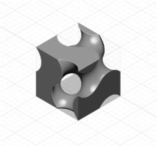
Fundamental cells of lattice structures.


Lattice structure modeling.

Lattice structure samples.

The FDM 3D printer used was an MA3D printer, with TPU Filament Flexible STTPU-AMS used for FDM printing. The SLS printer used was a Farsoon-FS403P, with Ultrasint TPU® 88A as the TPU material. The PolyJet 3D printer used was a Stratasys J850, with Agilus 30 as the material.
Because of the thinness of the sample model, little impact resulted from the amount of internal fill. However, to develop a sample that is as lightweight as possible and suitable for developing a lumbar support brace, the default settings of 20% infill and two walls (approximately 0.8 mm per wall) were used for FDM output. In contrast, for SLS and PolyJet printing methods, an infill rate of 100% was applied because these methods exclusively permit full internal-fill production. In this study, the infill rate varied depending on the manufacturing method as the goal was to achieve the lightest possible weight without sacrificing functionality.
Experiments
Tensile strength
Tensile strength stands as a pivotal indicator of material robustness, particularly crucial in assessing the suitability of lumbar support braces for postural correction and back protection. Therefore, tensile strength was measured to determine if it was strong enough to correct the back. A 1710 Titan 5 (James H. Heal & Co., USA) tensile-strength tester was used. Because lattice structures contain empty spaces, samples that meet the tensile strength test standards could not be manufactured and tested. Samples that meet these standards require a certain shape, and experiments can only be conducted if they have a standardized shape. Therefore, we directly performed tensile tests by referring to the principles and setting methods stipulated by the KS M ISO 527-1 standard. Both extremities of the sample were securely clamped within the tester’s grips, set 30 mm apart, with a tensile speed of 100 mm/min. Figure 1 shows a picture of the apparatus used to measure tensile strength. Tensile-strength measuring device.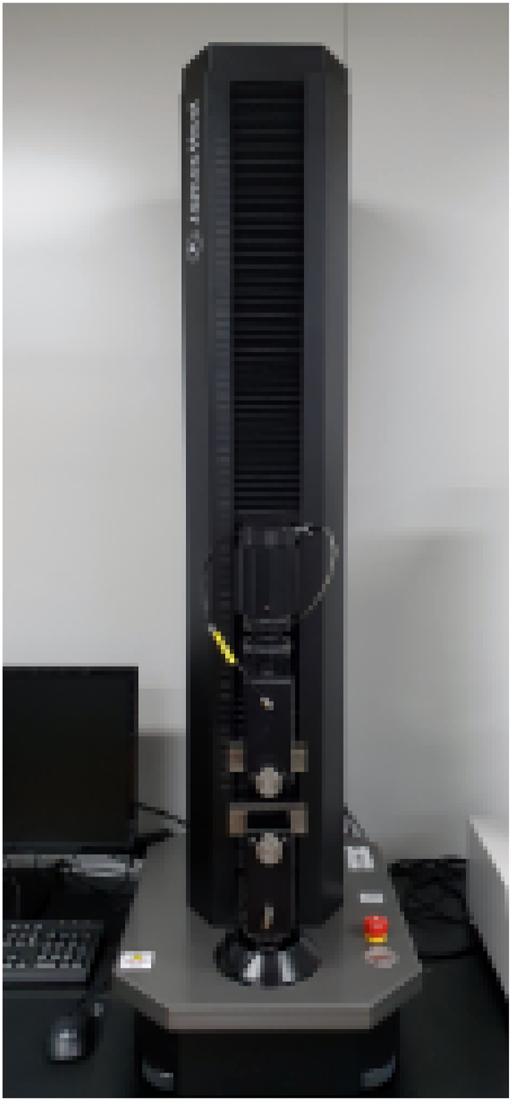
Bending strength
Due to the flexibility of the samples, which precluded testing in accordance with the standard three-point flexural test, we devised a bending-strength test utilizing a push–pull gauge. A push–pull gauge (AIGU, China) was used to measure the force (load) necessary for sample bending, as illustrated in Figure 2. To measure the bending strength, one half and one fourth of the total length of the sample were fixed with rubber cables, and the force required to bend 30° and 60° was measured (Figure 3). Push–pull gauge. Experimental environment.

The bending points were set at one half and one fourth of the sample length because the future lumbar support brace is expected to wrap around the entire body, and the bending force is expected to be applied at the center and one fourth of the lumbar support brace, respectively. The waist angle that is commonly bent in simple exercises and daily life is 30°, and the waist angle at which changes in muscle activity occur is 60°.
24
Moreover, a previous study
25
that investigated lumbar muscle-strength characteristics with respect to waist angle also used a 60° waist angle. Consequently, the bending angles for the sample were designated as 30° and 60° in this study. Bending strength was measured by applying force to the center of the sample segment using a push–pull gauge (Figure 4). Each sample underwent three bending-strength measurements, with the average of those measurements used to derive the final result. Experimental method.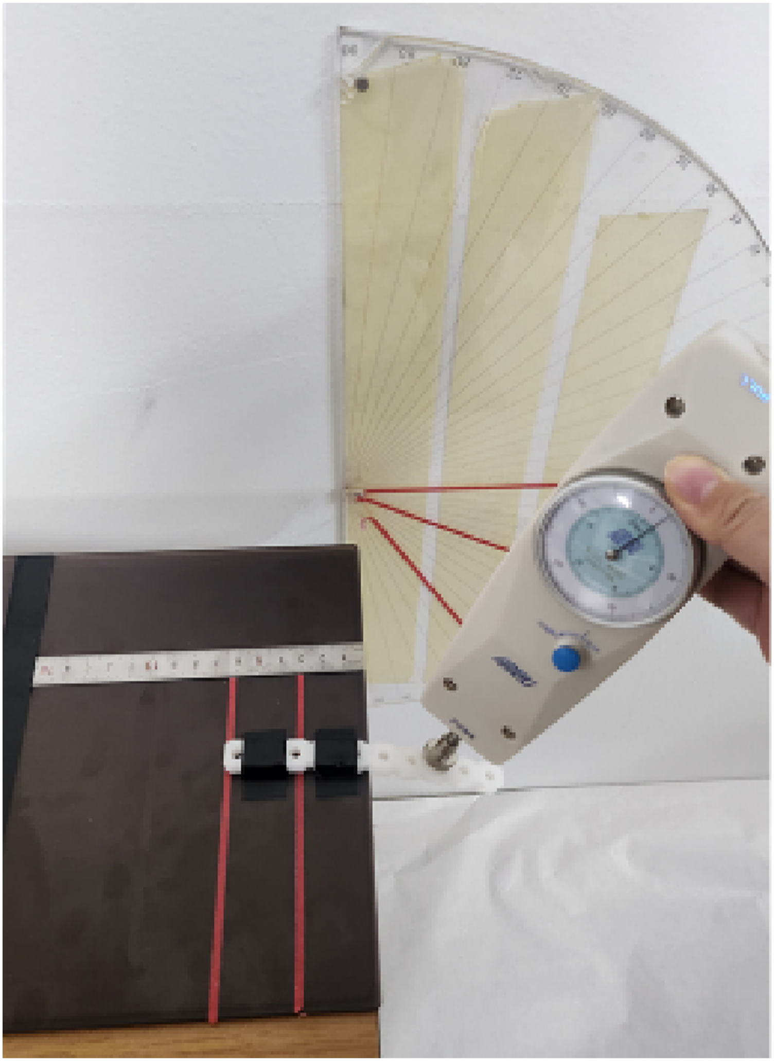
Weight/density
Because a lumbar support brace is worn closely against the body in everyday life, its weight is a critical factor to consider. Accordingly, the 36 samples were weighed, and a prediction was made regarding the strain that a lumbar support brace constructed from those samples would impose on the body.
Density is a factor that affects the strength and weight of a sample. Therefore, in this study, Archimedes’ principle was used to measure the density of the samples. This principle, grounded in fundamental laws of physics, stipulates that the upward buoyant force acting on an object immersed in a fluid equates to the weight of the fluid displaced by the object.
26
Figure 5 shows the instrumentation used for measuring weight and density. Apparatus for determining density using Archimedes’ principle.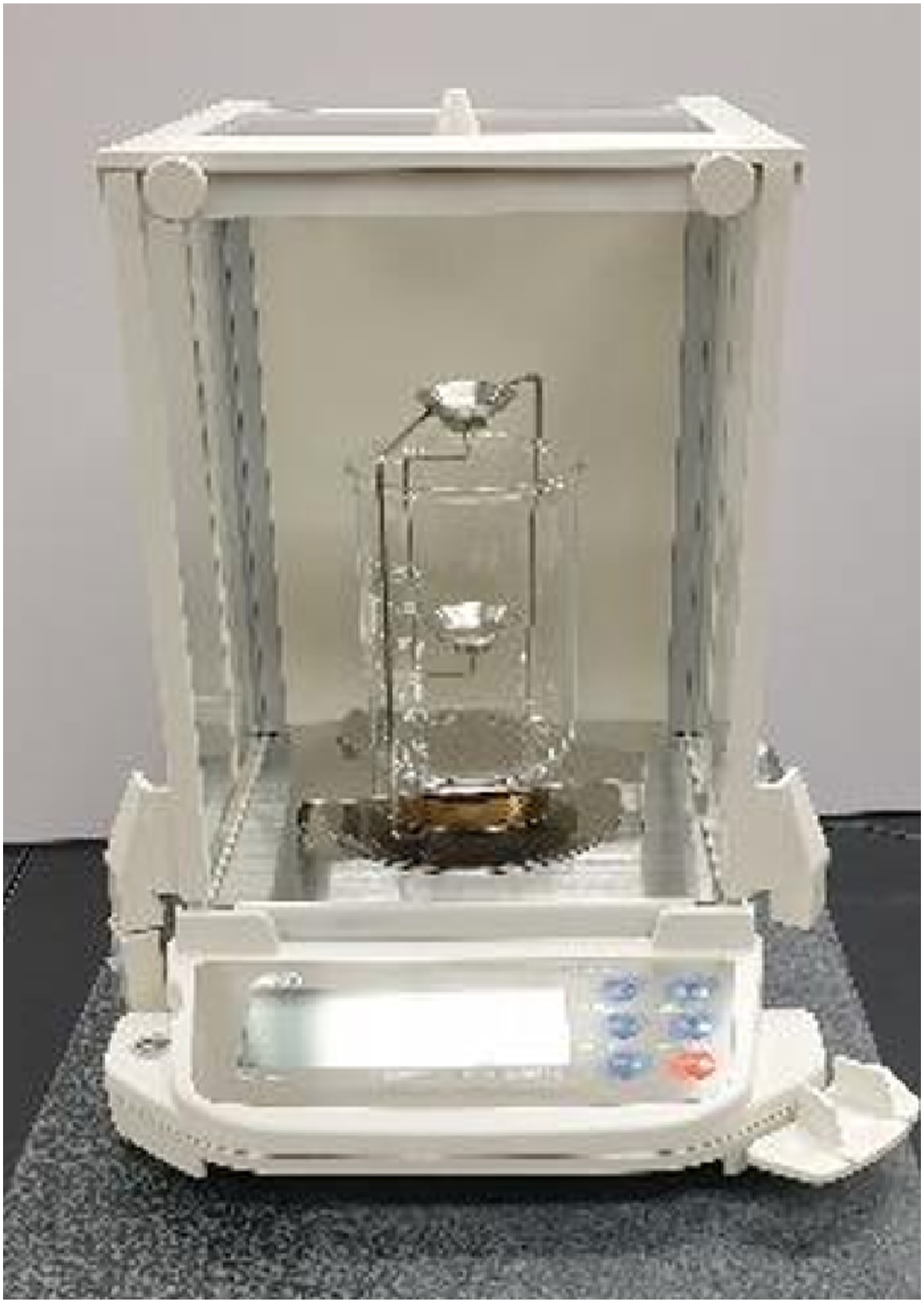
Results
Tensile strength
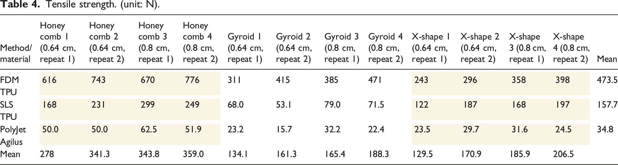
Tensile strength. (unit: N).
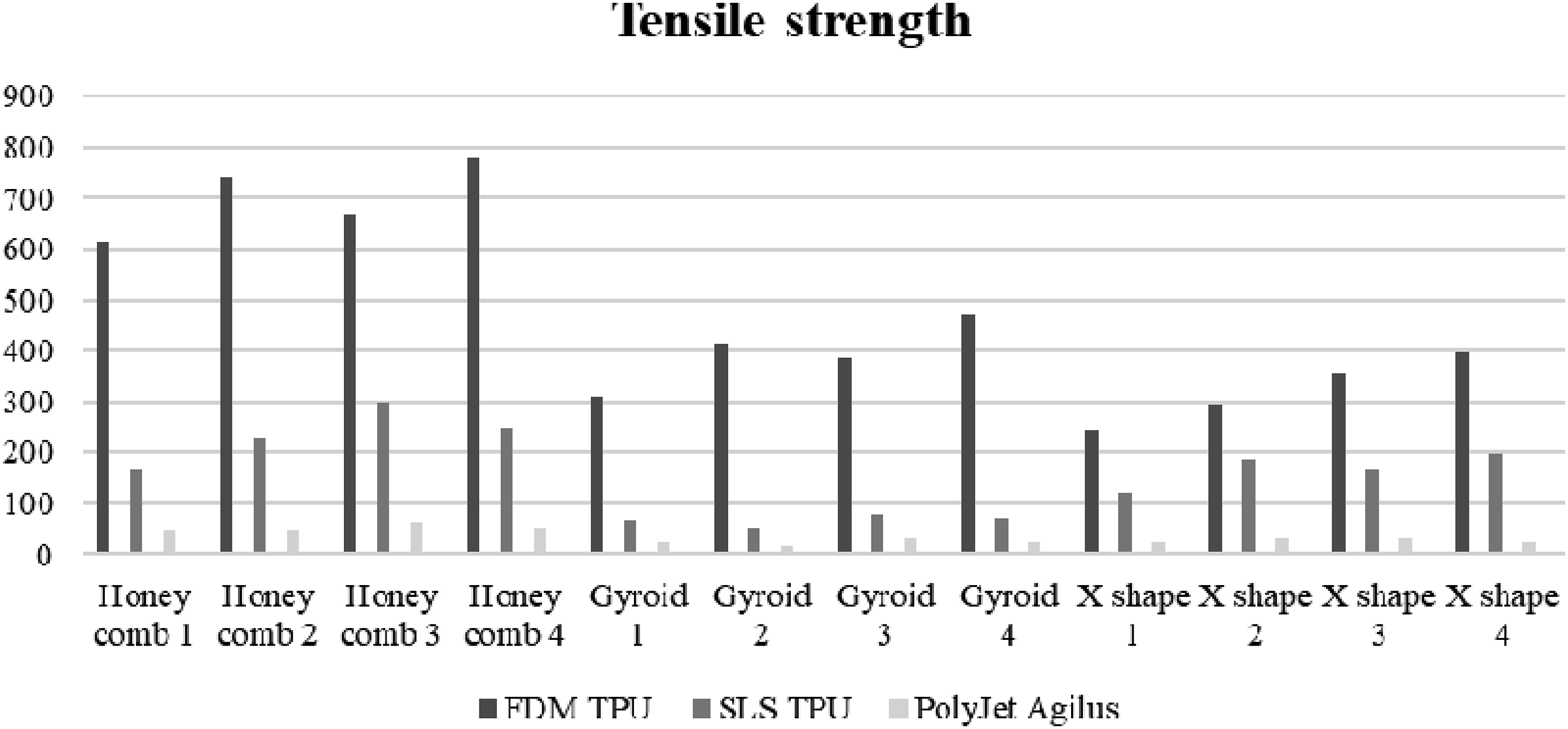
Tensile-strength graph.
Furthermore, when comparing tensile strength between the honeycomb and X-shape structures, the former exhibits approximately 1.4 to 2.5 times higher tensile strength. Conversely, the comparison of tensile strength between gyroid and X-shaped samples yields a disparate trend. The tensile strength of the PolyJet method with Agilus material is not significantly different from the tensile strength of the gyroid structure and the X-shape structure. However, when produced by the FDM method with TPU material, samples with the gyroid structure showed greater tensile strength than samples with the X-shape structure regardless of pattern repeat and thickness, whereas samples with the X-shape structure showed greater tensile strength when produced by the SLS method with TPU material.
On comparing the various materials and output methods, it was discerned that samples fabricated through the FDM method with TPU material exhibited the highest tensile strength, succeeded by those produced via the SLS method with TPU material and the PolyJet method with Agilus material. Notably, although FDM and SLS methods both used TPU material, samples printed using the FDM method exhibited higher tensile-strength output. The tensile strength of samples produced by the FDM method with TPU material was 2.2 to 3.6 times higher than that of samples produced by the SLS method with TPU material in the honeycomb structure, 4.6 to 7.8 times higher in the gyroid structure, and 1.6 to 2.1 times higher in the X-shape structure.
Conversely, samples generated through the PolyJet method with Agilus material demonstrated markedly lower tensile strength relative to samples derived from other materials and printing methods. This is a 10- to 20-fold difference, considering that the tensile strength of samples produced by FDM with TPU is 600 to 700 N in the honeycomb structure, 300 to 400 N in the gyroid structure, and 200 to 300 N in the X-shape structure.
For the thickness variable, it was observed that the thicker samples (0.8 cm) represented by samples 3 and 4 consistently exhibited higher tensile-strength values overall compared with the thinner counterparts (0.64 cm). However, outcomes pertaining to the pattern-repeat variable exhibited variability contingent on the sample’s structure, material composition, and 3D printing method.
Considering the average calculated values, all samples produced using the FDM method with TPU material had higher tensile strength values with repeat 2 than with repeat 1. However, samples produced via the SLS method with TPU material had higher tensile-strength values with repeat 1 than with repeat 2 for the gyroid structure, whereas the opposite trend was observed for the X-shape structure, with repeat 2 yielding higher tensile-strength values. Samples made with the PolyJet method with Agilus material showed smaller tensile-strength values and no clear trend in the numbers.
The results of the tensile-strength test show that values vary depending on the structure and material of the sample and the 3D printing method.
Bending strength
Bending strength. (unit: kgf).


Bending-strength graph.
On examining the average bending-strength values across the lattice structure variables, the honeycomb structure exhibited the highest bending-strength load, followed by the X-shape and then the gyroid structure. Specifically, the bending strength of the honeycomb samples exceeded that of the gyroid samples by 1.4 to 2.7 times and that of the X-shape samples by 1.1 to 3.2 times. The results showing that the honeycomb and X-shaped samples had a certain level of strength were similar to the previous study by Dong et al. 27
Regarding the printing method and material, samples produced through the FDM method with TPU material demonstrated the highest bending-strength load overall, followed by those manufactured via the SLS method with TPU material, whereas samples printed with the PolyJet method with Agilus material exhibited the lowest bending strength. Samples made of Agilus materials weighed more than samples made of other materials in the weight test. Because the test methodology involves pushing down on the sample to measure the bending strength, it is possible that the weight of the sample might have caused it to require less force to bend.
Samples generated through the FDM method in TPU showed 1.2 to 2.7 times higher bending-strength loads than samples produced by the SLS method in TPU and 1.1 to 3.2 times higher loads than samples produced by the PolyJet method in Agilus material. That comparison underscores the influence of 3D printing method on bending strength, even when using the same TPU material.
Moreover, the thickness and pattern-repeat variables exhibited a consistent trend in bending-strength results, with thicker samples and those with repeat 2 displaying higher load values. Samples made of Agilus material have lower flexural-strength values and a lower flexural modulus than samples made of TPU material. However, it is judged that the strength can be supplemented by setting the output hardness higher when printing samples made of Agilus materials.
Weight
Weight. (unit: g).


Weight graph.
For the lattice structure variable, regardless of the material and output method, samples with honeycomb structure are clearly heavier than samples with the other two structures. The X-shape samples were the next heaviest, and the gyroid samples were the lightest. Comparing sample weights across all variables revealed that honeycomb structure samples were approximately 1.3 to 1.6 times heavier than gyroid structure samples and 0.8 to 0.9 times heavier than X-shape structure samples, suggesting negligible variation across material, printing method, and pattern-repeat variables.
The comparison of materials and printing methods confirmed that samples created via the PolyJet method using Agilus are the heaviest, with an average weight of 8.7832 g. The weight discrepancy between samples produced via the FDM method with TPU material and those from the SLS method with TPU material varies depends on the structure and pattern repeat. In the honeycomb and gyroid structures, the SLS method with TPU material was heavier than the FDM method with TPU material in the case of repeat 1, whereas the opposite trend was observed in repeat 2. That variation is thought to result from the larger mesh size in the lattice structure of repeat 1 compared with repeat 2, leading to a slightly empty space inside the mesh when fabricated using the FDM method with TPU material. Conversely, for the X-shape structure, no distinct trend difference was observed between the FDM method with TPU material and the SLS method with TPU material.
Regarding the thickness variable, samples with a thickness of 0.8 cm exhibited greater weight than those with a thickness of 0.64 cm. The disparity in weight corresponds precisely to the difference in thickness, with an average difference of 1.25 times.
Density
Density (unit: g/cm3).


Density graph.
Concerning material and printing method, the PolyJet method using Agilus material demonstrated the highest density with an average of 1.1468, whereas samples fabricated through the FDM method with TPU material and the SLS method with TPU material exhibited varying density differences contingent on the pattern-repeat variable. Density of samples produced via the SLS method with TPU material surpassed that of those fabricated through the FDM method with TPU material for repeat 1, with the converse being observed for repeat 2. That difference ranges from 0.86 to 1.2 times, which is not considered significant, but it appears to be attributed to the FDM output method. Because of the layer-by-layer manufacturing process inherent in FDM printing, complex objects such as lattice structures might entail numerous internal supports which, even after postprocessing, could contribute to slightly higher density values in repeat 2 samples characterized by more intricate structures.
The thickness variable appears to exert minimal influence on density differences. When comparing samples 3 and 4 to samples 1 and 2, the multiplier is about 0.9 to 1.1 times, indicating highly similar density values across all samples.
Overall, density-test results are much more uniform than weight-test results, but the trend of the values depending on the material, fabrication method, and repeat is the same as the weight-test results. That uniformity underscores the minimal impact of lattice structure or thickness on density values, with density primarily influenced by the intrinsic density of the material itself and the number of lattice structures inserted. Consequently, the consistent density results affirm the precision and fidelity of the sample production process.
Conclusions
In this study, 36 samples were fabricated by manipulating variables encompassing lattice structure, 3D printing material and method, thickness, and pattern repeat, aimed at developing a lumbar support brace using lattice structure and 3D technology. The findings from mechanical tests of tensile strength, bending strength, weight, and density are summarized as follows.
Concerning tensile strength, the honeycomb structure exhibited the highest value compared with other lattice structure samples. When manufactured using the FDM method with TPU material, gyroid structure samples exhibited high tensile-strength values, and when manufactured using the SLS method with TPU material, the X-shape structure samples showed high tensile-strength values.
Furthermore, analyses across material and output-method variables revealed the highest tensile-strength values for samples manufactured using the FDM method with TPU material, followed by those manufactured through the SLS method with TPU material, with the PolyJet method with Agilus material yielding comparatively lower values. When looking at the pattern-repeat variable, all the samples produced by the FDM method with TPU material had higher tensile-strength values in repeat 2 than in repeat 1, but samples produced by the SLS method with TPU material had higher values in repeat 1 than in repeat 2.
Outcomes of the bending-strength tests exhibited a consistent trend across the investigated variables. For the lattice structure variable, the honeycomb structure demonstrated the highest bending-strength load, followed by the X-shape and gyroid structures. Similarly, regarding the material and printing-method variables, samples produced via the FDM method with TPU material exhibited the highest N value, followed by those fabricated through the SLS method with TPU material and finally, the PolyJet method with Agilus material. Furthermore, an observed trend across all samples indicated higher bending-strength load values for thicker samples, with samples produced through repeat 2 exhibiting greater bending strength compared with those from repeat 1.
Weight and density showed similar trends in the results. Across lattice structures, the honeycomb structure displayed the highest weight, succeeded by the X-shape and gyroid structures. In terms of weight by material and printing method, samples manufactured via the PolyJet method with Agilus material exhibited the highest weight, whereas variations in weight were noted for samples produced through the FDM method with TPU material and the SLS method with TPU material, contingent on the pattern-repeat variable. Trends observed in weight-test results were consistent with those of density measurements. Density was calculated using the Archimedes method, and density values of the 36 samples were almost unaffected by the lattice structure and thickness variables. However, discrepancies in material and printing method were noted. The Agilus sample, distinguished by its highest weight, exhibited the highest density compared with samples made by other materials and printing methods. Density of the samples made with the other two methods varied according to the pattern repeat, which was the same as the results of the weight measurement.
The objective of this investigation was to ascertain an appropriate 3D printing methodology and material for fabricating a lumbar support brace, considering the pivotal aspects of strength and weight, crucial for prolonged wearable application against the body. Findings from the mechanical tests conducted in this study discerned TPU material as the suitable choice for the lumbar support brace. That conclusion is derived from the necessity for the lumbar support to sustain requisite strength while minimizing discomfort caused by excessive weight during extended wear.
A comprehensive analysis of the results of the mechanical tests based on lattice structure shows that the honeycomb structure, which is a planar-based lattice that repeats and protrudes in one direction from the 2D plane, has low flexibility and high strength. In comparison, the gyroid structure, a surface-based lattice, is symmetrical and has multiple families to minimize surface area. Therefore, it is more flexible and lighter in weight, even when modeled with the same solidity. The X-shaped structure—which belongs to the most common lattice structure, the strut-based lattice—is a series of connected bars and is stiffer than the surface-based lattice. Therefore, its mechanical properties were generally intermediate compared with the other two structures.
Based on the results of the bending-strength test, it seems that the TPU material and FDM and SLS printing methods have adequate bending strength and elastic recovery, which are suitable for the production of the protector. Conversely, samples composed of Agilus material are anticipated to possess excessive weight and flexibility, potentially lacking the requisite strength for supporting the body. However, by setting the hardness to a higher level during the printing process, Agilus material can be made harder, necessitating further experimentation with samples of increased hardness. In this study, the hardness of the Agilus material was set to 70%. Increasing this hardness could enhance the material’s strength, allowing for a more comprehensive evaluation of whether Agilus possesses the necessary mechanical properties for use in lumbar support braces. The lumbar support should be sufficiently elastic to allow flexible body movements and help users maintain a good posture. However, the material lacks elasticity and is heavy, which is a disadvantage. Instead, Agilus is more appropriate for other purposes, such as in the manufacturing of shoes or soft wearables.
TPU material has high tensile and bending strength, which provides the strength to hold the body in place. Simultaneously, the flexibility of TPU allows the wearer to move and bend during daily activities. Furthermore, considering the thickness parameter, thinner options (0.64 cm) are deemed more favorable than thicker counterparts (0.8 cm) to mitigate discomfort during prolonged wear and to minimize production costs. In the case of pattern repeat, it is recommended to use a combination depending on the part of the lumbar support brace. Because repeat 2 exhibits higher tensile and bending strengths, it is advisable to use that configuration in areas of the lumbar support brace that require greater support for the body.
In addition to the experiments conducted in this study, understanding additional characteristics of the samples, such as surface roughness and breathability, is essential for the successful production of a lumbar support brace. Furthermore, it is expected that the application of the functional characteristics of the developed samples through follow-up studies will contribute to the production of more functional lumbar support braces.
Footnotes
Declaration of conflicting interests
The author(s) declared no potential conflicts of interest with respect to the research, authorship, and/or publication of this article.
Funding
The author(s) disclosed receipt of the following financial support for the research, authorship, and/or publication of this article: This work was supported by the National Research Foundation of Korea (NRF) grant funded by the Korean government (MSIT) (RS-2023-00276933).