
Abstract
A high purity Ni plating layer was obtained on the surface of the plain cotton fabric by electroless nickel plating. The micromorphology and elemental composition of the Ni plating layer were characterized by scanning electron microscopy (SEM) and energy dispersive spectroscopy (EDS). Structural absorbing composites with glass fiber (GFs)/epoxy resin (EP) as permeable layer, nickel coated fabric/EP as absorbing layer and carbon fiber UD cloth (UDCFs)/EP as reflecting layer were prepared by vacuum assisted resin perfusion (VARI). The effects of different thicknesses on the microwave absorption properties and mechanical properties of composites were investigated. The results show that the lowest reflection loss (RL) is −31.02 dB, the effective absorbing bandwidth (RL < −10 dB) is 6.21 GHz (11.55 GHz - 17.76 GHz), and the maximum tensile and bending loads endured are 41.36 KN and 1.63 KN at 15.14 GHz with a thickness of 2.5 mm, which provides a good reference value for the subsequent preparation of magnetic/dielectric composites with both excellent microwave absorption and mechanical properties.
Keywords
Introduction
The wide application of high-performance wireless devices, 1 intelligent electronic products, and radar systems has caused extremely serious electromagnetic wave interference pollution,2–4 and electromagnetic wave radiation can lead to the failure of internal interactions of surrounding devices and violate the inherent electromagnetic field of biological systems, adversely affecting the electromagnetic field inside humans.5–8 In the military field, especially in stealth technology, the development of structural composites with both radar wave absorption and excellent mechanical properties is an important development trend to improve the viability and penetration ability of military action targets.9–12
Single-layer absorbing composites have narrow absorption bandwidth and have some limitations in application,13,14 combining materials with different properties into multi-layer composites can effectively improve absorbing properties in a wider frequency range.15–18 Multi-laminated absorbing composites, through a certain structural design, can endow the material with excellent absorbing properties, the bearing capacity of the material is not affected, the material comprehensive performance is better, and the designability is more flexible.19,20 ADH et al. prepared a structural absorbing material with glass fiber as reinforcement and high dielectric constant short carbon fiber cloth as the absorber by autoclave curing with epoxy resin as binder and randomly and layers of short carbon fibers were inserted into glass fibers uniformly distributed in a random direction. 21 The results showed that when the design thickness was 3.464 mm, the minimum reflection loss was −25.95 dB and the effective absorption bandwidth was 11.55 GHz from 8.79 GHz to 16.37 GHz, the composite material was composed of 12 layers of glass/epoxy resin and seven layers of UDCFs/epoxy resin. Cai Haishuo et al. prepared double-layer absorbing composites with CIPs/GFs/EP as absorbing layer and CFs/EP as reflecting layer using VARI process. When the thickness was 2.5 mm, the minimum reflection loss of CIPs/GFs/CFs/EP composite plate was −26.5 dB, and the effective absorption bandwidth was 3.6 GHz (9.8 - 13.4 GHz). 22 Metalized textiles prepared by electroless plating have good electromagnetic wave absorbing ability and can be cut arbitrarily with low cost and simple process. Ni nanoparticles can be deposited on the fabric surface by reducing agents in the plating solution to form uniform Ni alloy coating films. 23 Kwak et al. used electroless plating to uniformly deposit Ni layer films on flat glass fiber fabrics and finally formed continuous nickel coatings with a thickness of 40 to 80 nm. 24 Chen Yangjie et al. obtained uniformly dense Cu/Ni bilayer metal coatings on the silk fabric surface using iron monolayers as catalytic centers. 25
Herein, a uniform and dense Ni alloy coating is formed on the plain cotton fabric by electroless nickel plating. Ni nanoparticles can serve as electromagnetic wave absorbing materials with high magnetic losses due to their high magnetic permeability. Epoxy resin was used as the matrix, glass fibre fabric and unidirectional UDCF were used as reinforcement materials, and multilayer absorber panels with both wave absorbing properties and mechanical properties were prepared by the VARI process. By controlling the number of layers, the influence of plate thickness on the reflection loss, tensile properties, and bending properties of absorbing composites is compared and analyzed, which provides theoretical guidance for the preparation of absorbing/mechanical multifunctional integrated composites.
Experimental
Experimental materials and reagents
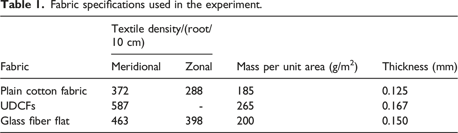
Fabric specifications used in the experiment.
Preparation of nickel plated fabric
The chemical plating method is to deposit metal materials onto the surface of fibers by catalytic dissolution of metal ions in aqueous solution. This type of plating does not require an external power source, has high uniformity and chemical properties, and is capable of prolonging the service life of metal materials and enhancing wear resistance. When using the chemical nickel plating method, it is especially important to control the hydrogen precipitation reaction of the activation process. The process flow is pretreatment (degreasing) → roughening →ultrasonic activation → chemical nickel plating. The pretreatment of electroless nickel plating can make the surface of the fabric more uniformly plated with nickel.26,27
For fabric pretreatment, plain cotton fabrics, cut to 25 cm × 20 cm, were first soaked in ethanol for 15 min and then removed, then ultrasonicated (Pw: 150 W) for 40 min, and finally, dried in an oven for 2 hours, were impurities and oils on the samples were removed.
Acid treatment; Put the pretreated fabric in a beaker, fill it with 32 g of ammonium persulfate, 16 mL of sulfuric acid concentrate, and 150 mL of deionized water. Stir thoroughly, then acid-treat for 10 minutes at 60°C.
Ultrasonic activation: Ultrasonic activation treatment results in enhanced surface activity and uniform dispersion of the reactants. Place the treated fabric in 15 g/L nickel sulfate and 10 g/L sodium hypophosphite solution, activate in an ultrasonic cleaner at 80°C for 60 min, and take out for drying.
Nickel coating of fabric: Chemical plating is a process in which free metal ions in the plating solution are reduced to atoms by a reducing agent without the application of an external current and deposited onto a substrate with autocatalytic activity to form a metal coating. Place the activated fabric in the plating solution, coat it at 90°C and pH five for 1 h, take out the cloth, and put it into a 60°C drying oven for drying. The concentration composition of the plating bath is NiSO4•6H2O (20 g/L), NaH2PO2•H2O (15 g/L), C6H5Na3O7 (5 g/L), CH3COONa (5 g/L). Fabric electroless nickel plating process flow as shown in Figure 1. Process flow diagram of chemical nickel plating on fabrics.
Design of absorbing composite layer
The carbon fiber UD fabric and glass fiber fabric were cut into 25 cm × 20 cm samples, and the absorbing composites with glass fiber (GFs)/epoxy resin (EP) as the surface permeable layer, nickel plated fabric/EP as the intermediate absorbing layer, and carbon fiber UD fabric (UDCFs)/EP as the bottom plate reflector were prepared by vacuum assisted resin perfusion process (VARI). The number of layers of glass fiber and UDCFs can influence the thickness, absorbing properties, and mechanical properties of the composites.
Preparation of glass fibers /nickel plated fabric/carbon fiber UD cloth/epoxy resin absorbing composites
The VARI molding equipment uses a laboratory-made vacuum device, which is schematically shown in Figure 2, using 500 mm × 400 mm tempered glass as a mold. First, the tempered glass was placed on a flat experimental operating table, and the sealant was pasted after cleaning the mold, followed by three applications of mold release agent at 15-min intervals. After applying the release agent, UDCFs, nickel plated fabric, glass fiber, diversion net, demoulding cloth and vacuum bag film were placed in sequence, resin injection tube and resin outlet tube were placed in the vacuum bag film, and finally the vacuum bag film was tightly bonded with the sealing adhesive. Vacuum perfusion can be performed when the vacuum pump is turned on and the device is pumped to negative pressure (below 0.09 MPa). The number of layers of glass fiber and UDCFs is shown in Table 2. Schematic diagram of molding for VARI. Number of layers of glass fiber and UDCFs layups.

Performance testing and characterization
Microscopic morphology and chemical composition
JSM-7800F scanning electron microscope (SEM) was used to observe the surface morphology and coating distribution of nickel coated fabrics, and energy dispersive spectroscopy (EDS) attached to electron microscope was used to analyze the coating composition.
A D8 Advance X-ray diffractometer from Bruker, Germany was used to characterise the crystalline form of the nickel-plated cotton fabrics of the present experimental samples. The samples were cut into prescribed size samples pre-sample tray pressed flat and then tested using Cu Kα rays (λ = 0.15,406 nm) at 40 KV with scanning angle 2θ of 10-80°.
Electromagnetic wave-absorbing test
In the range of 2 - 18 GHz, the reflectance of samples with different thicknesses was tested by bow method according to GJB2038A-2011 standard, and the effect of thickness on the absorption properties of the composites was analyzed.
Mechanical performance test
The mechanical properties of the samples were tested by CMT550 universal testing machine. The tensile test was performed according to GB/T 1447-2005 Fiber-reinforced plastics tensile properties test method. The specimen size was 250 mm (length) × 25 mm (width) × d (thickness), the clamping distance was 200 mm, and the test speed was 2 mm/min.
The bending test is conducted according to GB/T 1449-2005 Test method for flexural properties of fiber reinforced plastics. The test parameters are: 40 mm (length) × 15 mm (width) × d (thickness), span is set as 32 mm, and loading rate is 2 mm/min. Five specimens were tested for each specimen and averaged.
Digital simply supported beam impact performance testing, the use of digital simply supported beam impact testing machine (XJJD-50) for simply supported beam impact, according to GB/T1043-93 for the test, the width of the sample (13 ± 0.2 mm), the length of the sample (120 mm ± 0.2 mm), the impact energy of 50 J, the impact direction is perpendicular to the specimen in the direction of the length of the diameter of an average of the test five samples, the final average value is the final result. 28
The impact strength is calculated by the formula:
Results and discussion
Micromorphology and phase analysis of nickel plated fabrics
As can be seen from the SEM images of the specimens, the surface of the unmodified fabric Figure 3(a) contained a small amount of impurities, with some grooves and pits along the fiber axis. Bright Ni nanoparticles were deposited on the surface of the activated fabric Figure 3(b), and Ni nanoparticles reduced by NaH2PO2•H2O from NiSO4•6H2O were used as autocatalytic layers in nickel plating of the fabric to accelerate the nucleation rate of Ni nanoparticles and bind more firmly to the fabric.27,29 Figure 3(c) shows the morphology of the chemically plated electroplated nickel base layer after the thickening treatment. 1h of nickel plating on the fabric surface produces a dense coating of Ni nanoparticles, and the Ni nanoparticles are also completely deposited in the tiny fibre faults. It can be seen that the diameter of the fibers became thicker, the thickening of the nickel plating layer was obvious, and a large number of spherical agglomerates appeared, forming a unique spherical nodular structure. This indicates that the process of chemical nickel plating is reliable. The mapping of EDS elements on the surface of Ni-plated fabrics showed that Ni nanoparticles were evenly distributed on the fabrics Figure 3(d). In addition, since cotton fabrics are mainly cellulose derivatives composed of C and O, mapping plots e, f clearly demonstrate their presence in the microstructure. The content of Ni far exceeds that of C, again demonstrating the successful loading of Ni nanoparticles on the fiber surface. (a) SEM of unmodified fabrics; (b) SEM of fabrics after activation; Fig. (c) SEM of fabrics after 1h of nickel plating; Fig. (d-f) EDS of fabrics after 1h of nickel plating.
Figure 4 shows the XRD spectrum of the nickel plated cotton fabric. The diffraction pattern coincides with the standard pattern of metal Ni, and the crystal planes of the diffraction peaks are (111) and (200), respectively, which indicates that the cotton fabric was successfully nickel-plated. This is in agreement with the results measured by EDS above, which is a good indication that the prepared nickel-plated cotton fabric has a pure and uniform coating. XRD spectra of nickel-plated cotton fabrics.
Analysis of absorption properties of GFs/Nickel plated fabric/UDCFs/EP composites
When the reflection loss is < −10 dB, it means that the material can attenuate more than 90% of the electromagnetic wave, and the corresponding frequency width at this time is called the effective absorption bandwidth.30–32 Figure 5 shows the reflection loss curves of GFs/Nickel Plated Fabric/UDCFs/EP Composites in the thickness range of 0-3 mm and the frequency range of 2-18 GHz. The samples show good electromagnetic wave absorption in the high frequency range of 12-18 GHz, and all of them can achieve reflection loss <−10 dB, which means that the materials can attenuate more than 90% of electromagnetic waves.
33
Reflection loss plots for different thicknesses of GFs/Nickel plated fabrics/UDCFs/Eps. (a) 2D reflection loss map (b) 3D reflection loss map (c) top view of reflection loss.
Thickness and wave-absorption band of GFs/Nickel Plated Fabric/UDCFs/EP Composites.

When the thickness is in the range of 1 mm-2 mm, the microwave absorption performance increases positively with the increase of the thickness (i.e., the number of fiber layers), but the fluctuation range is small, when the thickness is up to 2.5 mm, the RL of the No.4 sample is −31.02 dB at 15.14 GHz, which is 112.1% higher than that of the No.1 sample. However, the effective bandwidth of the sample decreases slightly from 1 mm to 1.5 mm, which is caused by the lack of synergy between Ni nano absorbing particles and fiber reinforcement in the sample. Nickel coated fabric/EP inside GFs/UDCFs/EP absorbing composites as absorbing layer and laminate structure determines the absorbing performance of the sample. The excellent permeability of glass fiber/EP realizes excellent impedance matching between free space and sample, thus allowing more electromagnetic waves to enter the sample interior to be absorbed and dissipated; Ni nano-absorbing particles in nickel-plated fabric/EP transform electromagnetic energy into thermal energy and attenuate electromagnetic waves mainly in the form of magnetic loss caused by natural resonance and exchange resonance. At the same time, the spherical aggregation of Ni nanoparticles can transmit electromagnetic waves from one microsphere to another microsphere during the transmission process, resulting in multiple scattering and reflection, providing a significant heterogeneous interface, which is conducive to multi-interface polarization to further attenuate electromagnetic waves, and also leads to a significant enhancement of the high-frequency absorption performance of the sample. When the electromagnetic wave enters the test sample, multiple reflections occur inside the sample, some of which are reflected into free space, and the other part enters the inside of the lamellar structure from the overlapping fibers. In the inner pore, multiple reflections deplete the energy of the wave and thus attenuate the electromagnetic wave. Because the UDCFs composite plate has excellent electromagnetic shielding properties, UDCFs/EP is selected as the reflection layer.
Figure 5 shows that the RL and effective bandwidth increase significantly when the thickness reaches 2.5 mm, which is attributed to the fact that there are more reflection points in the thicker specimen to facilitate the loss of electromagnetic waves inside the composite. In addition, when the thickness reaches 3 mm, the change range of RL and effective bandwidth is not obvious, which indicates that there is an addition threshold for the number of fiber layers, and excessive thickness does not greatly increase the RL value and effective bandwidth range, but on the contrary, it will increase the gram weight and cost of the sample. Therefore, when the thickness of GFs/Ni-coated fabrics/UDCFs/EP absorbing composites is 2.5 mm, the minimum RL is −31.02 dB at 15.14 GHz and the effective bandwidth is 6.21 GHz (11.55-17.76 GHz), which almost completely covers the Ku-band (12-18 GHz) in the high-frequency region.
Mechanical properties Analysis of GFs/Nickel plated fabric/UDCFs/EP absorbing
Composites
The tensile load-displacement curves of composites with different thicknesses are shown in Figure 6(a). From the figure, it can be seen that samples No.1-No.5 show typical stress-yield behavior, Table 3 shows the maximum tensile load indicating that the fiber-reinforced epoxy matrix composites have excellent plasticity during tensile process. With the increase in sample thickness, the maximum tensile load that the composite material can bear increases. When the thickness reaches 3 mm (No.5), the maximum load at which fracture occurs at 7.85 mm displacement is 59.43 KN, which is 154.9% higher than that of the sample with 1 mm thickness (No.1). This is because the UDCFs in the sample serve as reinforcement in the form of unidirectional layering, and the load applied to the sample will be transmitted to the reinforced fiber along the fiber axis to counteract the damage caused by the stress defects formed in the substrate. With the increase of applied load, the crack propagation increases due to the decrease of fiber/substrate interaction, the matrix cracking, interface debonding and fiber cracking lead to the loss of stiffness of the composite, and the crack expands abruptly, resulting in a significant yield point. Mechanical properties of composites with different thicknesses. (a) Tensile load-displacement graph; (b) Bending load-displacement graph; (c) Maximum load bar graph.
Maximum tensile load and maximum bending load for GFs/Nickel Plated Fabric/UDCFs/EP Composites.

The prepared wave-absorbing composite panels were water-cut and prepared to the required dimensions for the impact test according to the standard, and the specimens of the impact as well as the side views are shown in Figure 7(a) and (b). Figure 7(c) shows the impact test results of specimens of GFs/nickel-plated fabrics/UDCFs/Eps with different thicknesses. The glass fibers and UD carbon fibers are tightly bonded to the resin matrix, which improves the impact resistance of the composites. It can be seen that the impact resistance of the composites increases with the increase in the number of layers of glass fibers and UD carbon fiber fabrics. This is because the fibers are protected by the matrix and are less likely to crack, and when the crack extends to the glass fibers, the glass fibers absorb the impact energy, thus preventing the crack from extending. (a) Specimen of GFs/Nickel plated fabrics/UDCFs/Eps impact test; (b) Side of the sample; (c) Impact test results of Specimen of GFs/Nickel plated fabrics/UDCFs/Eps of different thicknesses.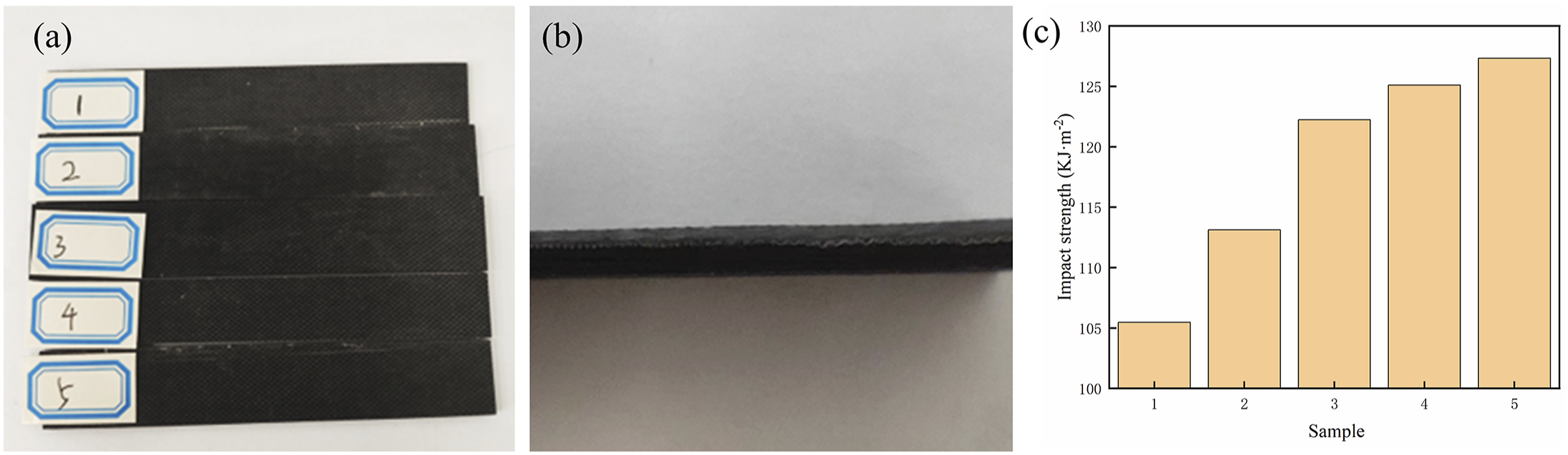
Conclusion
A high purity Ni plating layer was successfully obtained on the surface of the fabric by electroless plating. SEM and EDS were used to characterize the surface of the fabric. Structural composites with both absorbing and mechanical properties were prepared using epoxy resin as matrix and glass fiber and UDCFs as reinforcement materials. When the material thickness is in the range of 1 mm-2 mm, the microwave absorption performance increases with the increase of the thickness (i.e., the number of fiber layers). The RL value and effective bandwidth did not change significantly when the thickness reached 3 mm. When the thickness of GFs/Ni-coated fabric/UDCFs/EP absorbing composites is 2.5 mm, the lowest peak value of reflection loss is −31.02 dB, the effective bandwidth is 6.21 GHz (11.55 GHz-17.76 GHz), and the absorbing effect is obvious in Ku band. At the same time, the composites show excellent mechanical properties and their maximum tensile and bending loads can be 41.36 KN and 1.63 KN respectively. These results suggest that such GFs/Ni-coated fabric/UDCFs/EP absorbing composites have the potential to be promising wave-absorbing materials and deserve further investigation.
Footnotes
Declaration of conflicting interests
The author(s) declared no potential conflicts of interest with respect to the research, authorship, and/or publication of this article.
Funding
The author(s) disclosed receipt of the following financial support for the research, authorship, and/or publication of this article: This work was supported by the Shijiazhuang Municipal Science and Technology Bureau 2024 Hebei-based University Innovation Leadership Talent Team Project (Advanced Textile Functional Materials and Green Processing Technology Innovation Leadership Talent Team of Hebei University of Science and Technology).