
Abstract
The thermal conductivities of woven composites are strongly affected by the anisotropic properties of the reinforcing fibers, and thus by the fabric structure. In this study, the thermal conductivity of 2D woven composites was investigated by optimizing the fabric structures to enhance the through-thickness and in-plane thermal conductivities. Multiscale finite element models were developed to simulate the thermal behavior of various 2D fabric structures and evaluate their thermal performance under varying conditions, focusing on the effects of fiber tow undulation, dry-zone porosity, and matrix-rich zones. Fabric architectures were selected based on common 2D weavings of composites. The results showed that the tow undulation substantially enhanced the through-thickness conductivity and mitigated the impact of porosity. In addition, a higher tow anisotropy increased the effect of undulation. Moreover, the plain-weave fabric structures exhibited the highest through-thickness and in-plane thermal conductivities among the evaluated 2D woven fabrics in porous composites. Finally, the matrix-rich zones showed a stronger effect on the through-thickness than on the in-plane thermal conductivity of the 2D woven composites.
Keywords
Introduction
Woven composites are preferred over unidirectional composites because of their enhanced structural stability and damage tolerance 1 resulting from yarn weaving. Two-dimensional (2D) weaving is the most common process for changing the geometric configuration of reinforcement fibers owing to its simplicity. 2 Such 2D woven fabrics are widely used for manufacturing structural components. 3 Woven ceramic matrix composites (CMCs) have been extensively used in many high-temperature applications. Because of their good mechanical performance at elevated temperatures and in oxidizing environments, these composites are used in aerospace, nuclear, and conventional power generation. In these applications, the thermal properties, especially thermal conductivity, must be optimized because of their crucial role in performance. 4 Tailored weave patterns offer considerable design flexibility for optimizing the thermal performance of woven composite structures. 4 Therefore, a comparative analysis of the thermal conductivities of different types of woven fabric structures must be conducted.5,6 Existing studies provide substantial experimental and numerical evidence with focus on measuring and predicting the thermal properties of woven fabric composites. Plain-weave fabric structures have been the subject of extensive research.5,7–9 Siddiqui and Sun 10 used the finite element method to study the thermal behavior of 2D plain-weave materials. Alghamdi et al.11,12 performed experiments and multiscale finite element modeling to measure and predict the thermal conductivity of twill-weave composites. Zhang and Hayhurst 13 developed a theoretical model for predicting the through-thickness thermal conductivity of an eight-harness satin composite. Zhao et al. 14 investigated the effect of the fabric structure from three-dimensional (3D) composites on thermal conductivity. They conducted an experimental study on two 2.5-dimensional angle-interlock and 3D orthogonal woven composites. Li et al. 15 implemented a multiscale finite element modeling technique to assess the thermal conductivity and radiation characteristics of two 2.5-dimensional angle-interlock composites. Dong et al. 16 conducted experimental and numerical analyses to measure the thermal conduction properties of 2.5-dimensional angle-interlock woven composites. Sun et al. 17 constructed two-scale finite-element models to predict the thermal conductivities of five 2.5-dimensional and 3D woven composites.
Most existing studies on the effects of fabric architectures on thermal properties have been focused on a limited number of fabric structures. Comprehensive and comparative analyses were also performed on 2D fabric structures. For instance, Bhattacharjee and Kothari 18 developed a theoretical model to predict the through-thickness thermal resistance of 2D fabric structures made of cotton fibers, including plain, twill, and four-harness satins. Matusiak 19 conducted a similar study and found out that plain-weave fabric, which has the highest level of fiber tow undulation, has the lowest thermal resistance. In other words, this indicates the highest through-thickness thermal conductivity. However, the main drawbacks of these studies were that they considered isotropic thermal conductivity of the fibers. Moreover, they did not study the in-plane thermal resistance. Finally, all fabric structures were studied without matrices, which have a very strong effect on the thermal properties of the composite. This study aimed to overcome these drawbacks by constructing multiscale FE models to comprehensively compare the effects of six types of 2D woven fabric structures on the in-plane and through-thickness thermal conductivities. The effects of orientation-dependent material properties were also considered. In addition, the influences of dry-zone porosity and matrix-rich zones were evaluated.
Materials
Overview
This study was conducted using two different 2D woven composite materials, namely, DLR-XT and HITCO, which are used in various industries. Numerous studies have provided adequate information about the composite structures and experimental results of the thermal conductivities of both materials.7–9,13,20–24 In addition, the investigated materials have exhibited different 2D fabric structures, properties, and porosities. This information was used to further evaluate the fabric structures.
DLR-XT (C/C-SiC composite)
DLR-XT is a CMC with a plain-weave architecture. The German Aerospace Center developed this composite for aerospace and high-temperature applications involving parts of gas turbines. It consists of T800 carbon fiber tows weaved to produce a plain weave and obtain a single laminate. Ten of these laminates are stacked to form a sheet of DLR-XT composite. The 10 laminates are infiltrated with a polymer, which is thermally decomposed to leave carbon char. The lamina is then infiltrated with liquid silicon, which reacts with the carbon char to produce a silicon carbide (SiC) matrix around the carbon fiber tows. Therefore, the final product comprises carbon fibers embedded in a carbon matrix, which, as a whole, is surrounded by a SiC matrix, as shown in Figure 1. The volume fractions of the carbon matrix, carbon fiber, and SiC matrix are 13.65%, 48.75%, and 32.4%, respectively, and the porosity volume fraction is 2.6%. The density of DLR-XT composite is 1.72 g⋅cm−3. Scanning electron microscopy micrograph of DLR-XT microstructure.
7

HITCO (C/C composite)
HITCO is a CMC with an eight-harness weave. It consists of T300 carbon-fiber tows, used to develop the eight-harness weave and obtain a single laminate. Nine of these laminates are stacked and infiltrated with a carbon matrix to form a HITCO sheet. The carbon fiber, carbon matrix, and porosity volume fractions are 50%, 39%, and 11%, respectively. The density of HITCO composite is 1.66 g⋅cm−3.
Methods
Finite element models
The multiscale finite element modeling approach was utilized successfully in previous studies focusing on one type of weave per study.11,12,21–24 In this study, the same approach was adopted to study the thermal conductivity of six types of 2D woven composite. The multiscale finite element modeling approach incorporates all the microscale geometrical details of the composite architectures within the simulation models. Data from other studies were used to construct and validate these models. The finite element models with varying scales were created using the ABAQUS software package.
DLR-XT (C/C-SiC composite)
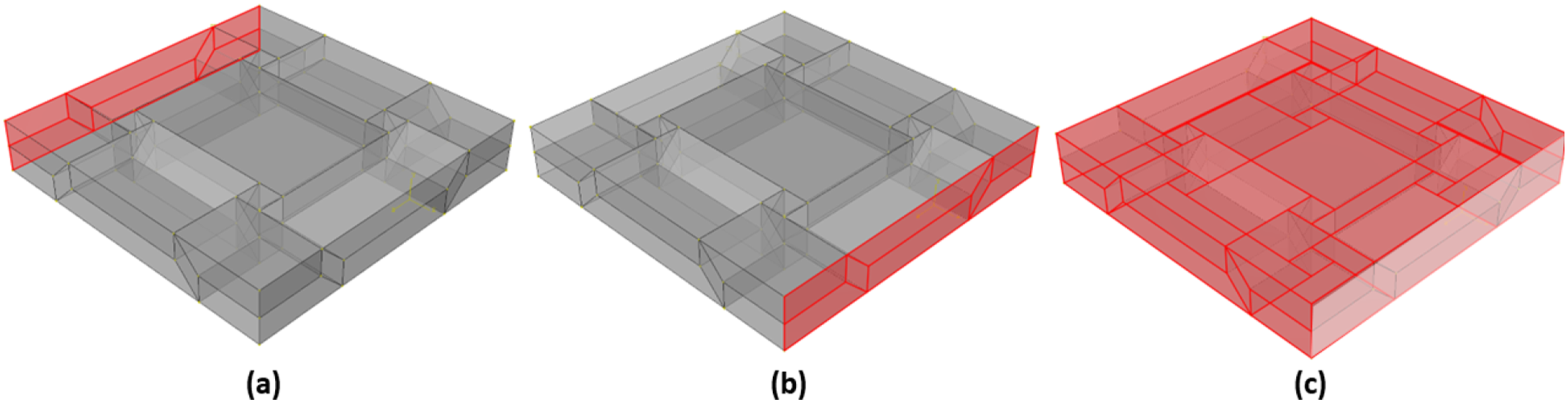
The model of DLR-XT (C/C-SiC composite) was divided into three scales, as shown in Figure 2. The C/C tow model was the first-scale model employed to calculate the thermal conductivity of a carbon tow consisting of carbon fibers embedded within a carbon matrix, as shown in Figure 2(a). The output result of the C/C tow model was then utilized in the second-scale model, the C/C-SiC tow model. It comprised a homogenous carbon tow surrounded and penetrated by a SiC matrix, as shown in Figure 2(b). The resulting in-plane and through-thickness thermal conductivities of the C/C-SiC tow model were used in the third-scale model, which was a plain-weave composite unit cell, as shown in Figure 2(c). The composite unit cell produced the fabric structure of a 2D woven composite by repeating it through translation on three spatial planes. It consisted of weft and warp tows. To improve the computational efficiency of simulating the composite unit cells, the cross-sections of the weft and warp tows were assumed to be rectangular (with aspect ratio = 5), and the tow undulation was modeled with straight and sharp cornered edges. The weft and warp tows were separated into straight and woven segments. The assignment of material properties of each section was based on its orientation. The straight tows along the X and Z axes are light blue and green, respectively, in Figure 2(c). In addition, the woven segments along the X and Z axes are indicated in red and dark blue, respectively. The last phase is porosity, which is indicated in orange. Multiscale modeling of DLR-XT (a) C/C tow, (b) C/C-SiC, and (c) composite unit cell.
HITCO (C/C composite)
The HITCO (C/C composite) model was divided into two scales, as shown in Figure 3. The C/C tow model was the first-scale model utilized to calculate the thermal conductivity of a carbon tow consisting of carbon fibers embedded within a carbon matrix, as shown in Figure 3(a). The output result of the C/C tow model was then employed in the second-scale model, the eight-harness satin weave composite unit cell, as shown in Figure 3(b). Multiscale modeling of HITCO (a) C/C tow, and (c) composite unit cell.
Data from other studies were used to construct and validate the models. Seven composite unit cells were constructed to simulate different 2D fabric structures. The 2D fabric structures were 0°/90° unidirectional, plain, twill, basket, and four-, five-, and eight-harness satin. Figure 4 shows different composite unit cells. Figure 5 shows the unit cell parameters on the side view of plain weave composite unit cells. The abbreviations W, T, and S represent the tow’s width, thickness, and spacing, respectively. These values were 0.803 mm, 0.161 mm, and 0.161 mm, respectively. The length of the unit cell (L) can be calculated from these parameters as follows: Composite unit cells of different types of 2D fabric structures. The unit cell parameters on the side view of plain weave composite unit cells.


Where N is the number of weft or warp per unit cell, which is 2, 5, and 8 for the plain weave, five-harness satin, and eight-harness satin, respectively, the twill, basket, and four-harness satin have the same number of weft or warp per unit cell, which is 4.
The total volume of the unit cell (V) is calculated as follows:

The total volume of the straight weft or warp (Vs) is calculated as follows:

The total volume of the woven segment in weft or warp (Vw) is calculated as follows:

The total volume of the Porosity/matrix-rich zone (Vp) is calculated as follows:

Volume fractions and porosities of different phases of composite unit cells.

Material properties of constituent materials of DLR-XT (C/C-SiC) and HITCO (C/C) composites.

As mentioned, the DLR-XT (C/C-SiC) and HITCO (C/C) composites have porosity volume fractions of 0.026 and 0.11, respectively. However, the porosity/matrix-rich zone within the plain and eight-harness satin are 0.028 and 0.132, respectively. Therefore, in the validation of the FE models, the rule of mixture was applied to the thermal conductivity of the porosity/matrix-rich zone as follows:
Boundary conditions
The boundary conditions included the application of a temperature gradient (i.e., difference in temperature) on two parallel and opposing faces of the model. The remaining faces of the model were simultaneously insulated. The specified boundary conditions resulted in a unidirectional heat flow toward the colder surface. Thermal conductivity k along a specific direction was calculated using Fourier’s law
27
as follows: Boundary conditions for through-thickness thermal conductivity prediction of a plain-weave unit cell showing locations of (a) high temperature, (b) low temperature, and (c) insulation. Boundary conditions for in-plane thermal conductivity prediction of plain-weave unit cell showing locations of (a) high temperature, (b) low temperature, and (c) insulation.

Results
Validation of finite element models
Thermal conductivities of different scale models of DLR-XT (C/C-SiC) composite.

Thermal conductivities of different scale models of HITCO (C/C) composite.

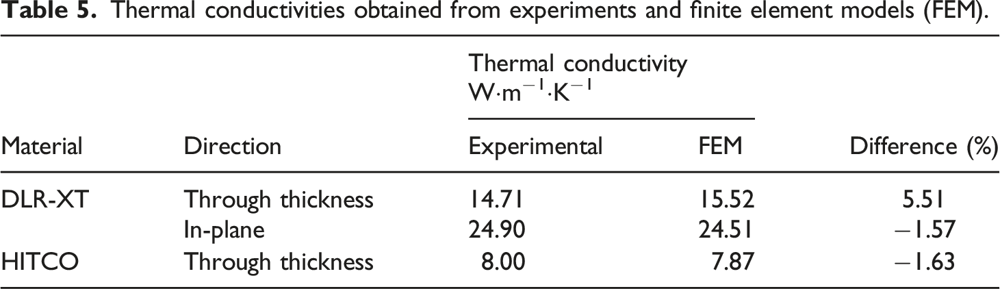
Thermal conductivities obtained from experiments and finite element models (FEM).
Effects of fabric structure
This study assessed two main parameters, with the fabric structure being the main parameter and the dry-zone porosity/matrix-rich zones, which also depended on the fabric structure, being the second parameter. Therefore, multiple simulations were conducted on each of the seven fabric unit cells to obtain the thermal conductivities in the in-plane and through-thickness directions for the dry-zone porosity and matrix-rich zones.
Thermal conductivity of C/C-SiC composite with different fabric structures.

Thermal conductivity of C/C composite with different fabric structures.


Change in thermal conductivity of C/C-SiC composite compared with those of 0°/90° unidirectional architecture for different fabric structures containing dry-zone porosities.

Change in thermal conductivity of C/C composite compared with those of 0°/90° unidirectional architecture for different fabric structures containing dry-zone porosities.
Change in thermal conductivity of C/C-SiC composite compared with those of 0°/90° unidirectional architecture for different fabric structures containing matrix-rich zones.

Change in thermal conductivity of C/C composite compared with those of 0°/90° unidirectional architecture for different fabric structures containing matrix-rich zones.
Effects of matrix and fiber thermal conductivity
Thermal conductivity of 4X C/C composite with different fabric structures.

Change in thermal conductivity of 4X C/C composite compared with those of 0°/90° unidirectional architecture for different fabric structures containing dry-zone porosities.

Change in thermal conductivity of 4X C/C composite compared with those of 0°/90° unidirectional architecture for different fabric structures containing matrix-rich zones.
Discussion
The porosity levels listed in Table 1 are related to the volume trapped between the woven tows of the composite. These volumes can be either matrix-rich zones following successful matrix penetration during manufacturing or porous dry zones following unsuccessful penetration. Therefore, every simulation was conducted twice to consider these volumes in the modeling procedure as the porosity and matrix. The results for the C/C-SiC, C/C, and 4X C/C composites are listed in Tables 6–8, respectively. Notably, heat transfer by conduction is the only mode considered in this steady-state analysis. This is because of the stagnant air within the porosity volumes and relatively low temperatures of the boundary conditions of the models.
For dry-zone porosity, all materials showed similar results, and the highest thermal conductivity was found in the unidirectional structure for the in-plane direction and in the plain fabric structure for the through-thickness direction. Overall, the thermal conductivities of both composites in the in-plane direction depended on the porosity level. The 0°/90° unidirectional configuration exhibited the minimum porosity and maximum thermal conductivity. In contrast, the eight-harness satin had the maximum porosity and minimum thermal conductivity. However, thermal conductivity in the through-thickness direction did not exhibit the same trend for either material. The woven segments of the tow played a major role in enhancing the through-thickness conductivity and mitigating the impact of porosity. This was obvious in the 4X C/C composite because the thermal conductivity anisotropy of the fiber tow of the C/C composite was higher than that in the C/C-SiC and C/C composites, as observed from Tables 3 and 4 The in-plane and through-thickness thermal conductivities of the fiber tow of the 4X C/C composite were 52 W⋅m−1⋅K−1, and 9 W⋅m−1⋅K−1, respectively. Simultaneously, those of the fiber tow of the C/C-SiC and C/C composites in the longitudinal direction were 32.56 W⋅m−1⋅K−1and 17.65 W⋅m−1⋅K−1, respectively, and 21.65 W⋅m−1⋅K−1and 8.11 W⋅m−1⋅K−1 in the transverse direction. The difference between the in-plane and through-thickness thermal conductivities of the C/C tow in the 4X C/C composite was more than four times that of the C/C-SiC and C/C composites. Therefore, the composite unit cell results differed, with the 0°/90° unidirectional specimen showing the second highest thermal conductivity after the plain weave structure.
The highest thermal conductivity of the 4X C/C composite with a matrix-rich zone in the in-plane direction was observed for the unidirectional and plain fabric structures in the through-thickness direction. The through-thickness direction followed the same trend as the dry-zone porosity. However, the results for the in-plane direction for the twill, basket, and harness satin depended on porosity. For example, the eight-harness satin exhibited the highest thermal conductivity. The C/C-SiC and C/C composites, on the contrary, had different results owing to the high thermal conductivity of the silicon carbide and carbon matrices (68 W⋅m−1⋅K−1 and 30 W⋅m−1⋅K−1). A greater matrix-rich zone in the model increased the thermal conductivity in both the in-plane and through-thickness directions. The plain fabric structure exhibited the lowest thermal conductivity in the in-plane direction.
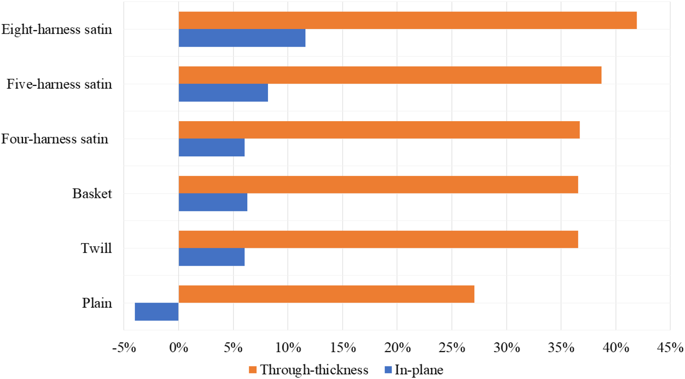
Figures 8–12 show the percentage change in the thermal conductivities of the C/C-SiC, C/C, and 4X C/C composites with different fabric structures containing dry-zone porosity, respectively. These charts show the influence of the woven segments and porosity on the thermal conductivities. Any positive changes in the thermal conductivity resulted from tow undulation in the woven part, while negative changes were caused by either the woven segments or porosity. The presence of woven segments in any 2D woven fabric was expected to enhance the thermal conductivity in the through-thickness direction at the expense of thermal conductivity in the in-plane direction. This was true for most 4X C/C composites, except for the eight-harness satin fabric. The woven segments increased the through-thickness thermal conductivity of plain weave and five-harness satin by 38% and 5%, respectively. The twill, basket, and four-harness satin experienced a similar increase of 8%. Despite the different architectures of these three fabric structures, they exhibited similar results throughout the study because they contained the same volume fraction (see Table 1). A positive change of only 13% and 10% in the through-thickness direction of the C/C-SiC and C/C composites, respectively, was observed for the plain weave. This was because of the difference between the longitudinal and through-thickness thermal conductivities of the tows. In the 4X C/C composite, the longitudinal thermal conductivity of the tow was nearly six times the through-thickness thermal conductivity. In the C/C-SiC and C/C composites, the longitudinal thermal conductivity of the tow was nearly twice the through-thickness thermal conductivity.
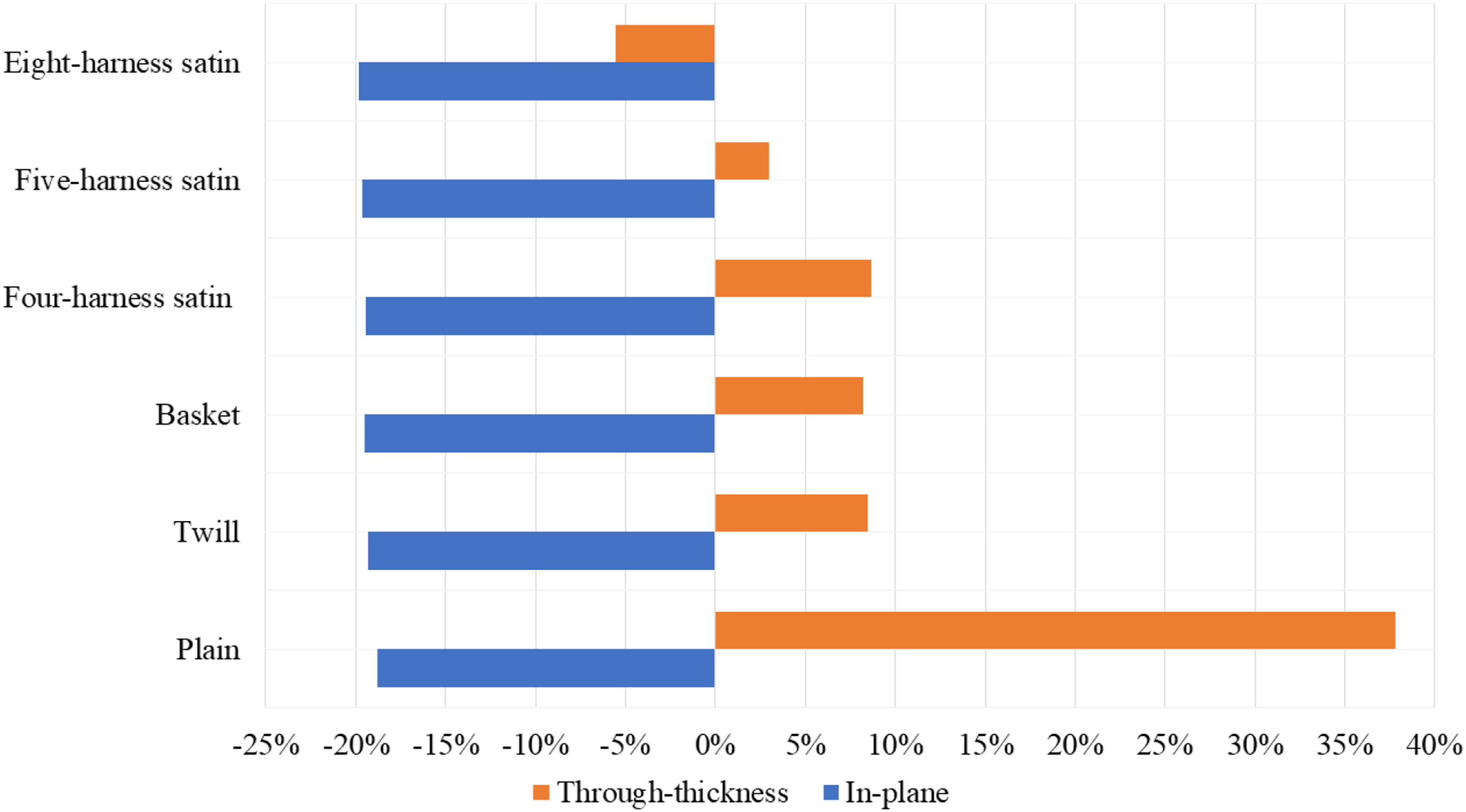
Figures 10, 11, and 13 show the percentage change in the thermal conductivity of the C/C-SiC, C/C, and 4X C/C composites with different fabric structures containing matrix-rich zones, respectively. The thermal conductivity of the C/C-SiC and C/C composites changed positively, except for that of the plain weave in the in-plane direction. The increase in through-thickness varied between 27% and 42%, whereas the in-plane direction was between −4% and 12%. The change in the thermal conductivity of the C/C composite in the through-thickness direction varied between 20% and 28%, while that in the in-plane direction varied between −5% and 7%.
The change in the thermal conductivity of the 4X C/C composite in the through-thickness direction varied between 12% and 41%, while that in the in-plane direction varied between −17% and −13%.
Matrix-rich zones had a more substantial effect on the C/C-SiC composite than on the C/C composite because the SiC matrix had a very high thermal conductivity (68 W⋅m−1⋅K−1) compared with that of carbon (30 W⋅m−1⋅K−1) and (10 W⋅m−1⋅K−1).
Conclusions
Various models at different scales were used to conduct steady-state finite element thermal analyses and predict the impact of the fabric structure on the thermal conductivities of C/C and C/C-SiC composites. The effects of the fiber tow undulation, dry-zone porosity, and matrix-rich zones caused by the fabric architecture on the thermal conductivities of the two composites were evaluated. Our main conclusions are as follows: 1. Multiscale finite element modeling demonstrated a high accuracy in predicting the thermal conductivities of the evaluated materials. 2. The through-thickness thermal conductivity of 2D woven fabric composites was not always better than that of unidirectional composites. 3. A higher difference between the longitudinal and through-thickness thermal conductivities of the tows resulted in more substantial undulation effects. 4. The undulation of the tows considerably enhanced the through-thickness conductivity and mitigated the impact of the porosity trapped between the woven tows of the composite. 5. Porous composites with plain-weave fabric structures had the highest through-thickness and in-plane thermal conductivities among the evaluated 2D woven fabrics. 6. Matrix-rich zones had a more substantial effect on the through-thickness than on the in-plane thermal conductivity of the 2D woven composite.
Footnotes
Acknowledgments
The author is grateful to Umm Al-Qura University (Makkah) for sabbatical leave No. 4402007947 that allowed the execution of this research.
Declaration of conflicting interests
The author(s) declared no potential conflicts of interest with respect to the research, authorship, and/or publication of this article.
Funding
The author(s) received no financial support for the research, authorship, and/or publication of this article.