
Abstract
This study focuses on investigating the impact properties of fiber-reinforced polymer (FRP) materials impregnated with shear thickening fluid (STF) under high strain rates using a split Hopkinson pressure bar (SHPB) test. The study involves the preparation of three types of FRP materials, namely aramid FRP (AFRP), basalt FRP (BFRP), and carbon FRP (CFRP), which are subsequently impregnated with STF to develop FRP composite materials (referred to as FRP-STF). The STF used in the experiment is synthesized by dispersing 15.0 wt.% and 20.0 wt.% of 12 nm silica in Polyethylene glycol. The results of rheological tests show a significant shear thickening effect on viscosity for both STFs. Furthermore, the SHPB tests demonstrate a noteworthy improvement in the impact performance of AFRP, BFRP, and CFRP under high strain rates when impregnated with STF. However, the extent of this improvement varies among the different types of FRP materials. For instance, BFRP exhibits the highest increase in stress peak, reaching 58.9% under a strain rate of 3800 s⁻1 and an STF mass fraction of 20%. AFRP demonstrates the most significant increase in energy absorption, reaching 226.8%. When subjected to a strain rate of 6100 s⁻1, the AFRP-20% STF composite exhibits a highly favorable stress response, while the CFRP-20% STF composite shows an energy absorption of 710.5 J, approximately 3.3 times higher than that of pure CFRP. These trends are also evident in the energy absorption per unit density curve.
Keywords
Introduction
Fiber-reinforced polymer (FRP) composites, which include aramid (AFRP), basalt (BFRP), and carbon (CFRP) fibers, have become widely used in quasi-static load-bearing structural members due to their impressive specific strength and stiffness.1–4 However, FRP composites are vulnerable to high strain rate impact loads, such as hail, vehicle collisions, and explosions.5–7 These impact loads can result in premature failure in FRP composites due to insufficient time for the initial internal defects in the fibers to dissipate.6,8–10 Therefore, it is crucial to enhance the impact resistance of FRP composites by incorporating additional materials to ensure their safe applicability in high strain rate impact conditions.
Various methods have been investigated to improve the impact resistance properties of FRP. Soliman et al. 11 conducted an analytical study to examine the response of thin CFRP fabric reinforced with functionalized multi-walled carbon nanotubes (MWCNTs) to low-velocity impact. They observed a 50% increase in energy absorption by adding 1.5% MWCNTs. Ismail et al. 12 also studied the after-impact behavior of MWCNTs in nanofiller-enhanced flax/carbon fiber composites and flax/glass fiber composites (FLXG) hybrid composites. They found that FLXG hybrid composites demonstrated good behavior for application as interior and functional surfaces in aircraft. Liu et al. 13 reported on the impact of embedded shape memory alloy (SMA) fibers on the mechanical performance of BFRP laminates hybridized with SMA fibers. The results demonstrated a significant enhancement in the mechanical performance of BFRP composite laminates by incorporating embedded SMA fibers. Iqbal et al. 14 confirmed that including nano-clay in the epoxy resin matrix helps transition the failure mechanism of CFRP laminates from brittle buckling to a more ductile multi-layer delamination mode. The study also determined that the optimal content for improving damage resistance is 3 wt% clay. Santhanam et al. 15 compared the flexural and Charpy impact properties of silicon carbide (SiC) and banana filler-reinforced BFRP composite structures. The results indicated that SiC in the BFRP composite exhibits exceptional impact energy absorption capabilities, surpassing those of banana filler. Bozkurt et al. 16 prepared basalt/aramid hybrid fiber-reinforced composite laminates to enhance the properties and behavior of ABFRP. The results confirmed an 82.3% improvement in the impact energy of aramid/epoxy composites through hybridization with low-cost natural basalt fiber.
While the research mentioned above enhances the mechanical properties of FRP under low-velocity impact, its impact resistance poses challenges in high-velocity impact scenarios. A recent noteworthy development involves a substantial increase in the viscosity of shear thickening fluid (STF), which presents significant potential in areas such as human protection,17–20 impact resistance,21–25 and vibration control.26–29 This potential stems from the ability of STF to absorb impact energy through its shear thickening mechanism. As a result, the integration of STF is expected to enhance the impact mechanical properties of FRP when exposed to high-velocity impact loads.
Lee et al. 17 conducted a pioneering study on Kevlar fabric impregnated with STF (Kevlar-STF). They discovered that SiO2 nanoparticles in the STF reduced the relative yarn slip between Kevlar-STF under high-velocity impact. Thus, STF can significantly enhance the ballistic performance of Kevlar. Additionally, under identical conditions, Kevlar-STF fabric exhibits superior characteristics in terms of thickness and softness compared to pure Kevlar fabric. Park et al.30,31 conducted high-velocity impact tests on Kevlar-STF fabric with impact velocities ranging from 1000 to 2000 m/s. Their study substantiated that STF notably increases the energy absorption capacity of Kevlar fabric, reaching approximately 70%. Haris et al. 32 investigated the influence of different STFs on the ballistic penetration performance of STF-Kevlar composites. The findings demonstrated that exceptional ballistic penetration performance is achieved only when the particle volume fraction exceeds a specific threshold. Avila et al. 33 fabricated aramid fiber composite fabrics by impregnating them with a bi-phase STF. The bulletproof performance of a four-layer configuration of this composite fabric was comparable to that of 32 layers of pure aramid fiber fabric. Hasan-nezhad et al. 34 examined the ballistic and cushioning properties of glass fiber reinforced polymer (GFRP) impregnated with pure STF and treated STF using air-gun and drop hammer impact tests. The ballistics tests showed that STF efficiently reduces the penetration depth of GFRP, and the performance of STF significantly affects the ballistic performance.
The existing literature provides evidence of the effectiveness of STF in enhancing the ballistic impact properties of Kevlar fabrics. In contrast, the use of STF in FRP, especially for high strain rate loading scenarios, is relatively uncommon. Therefore, the main objective of this study is to investigate the impact behavior of AFRP-STF, BFRP-STF, and CFRP-STF composites under high strain rate loading conditions. The mechanical properties of FRP-STF, at varying high strain rates, were evaluated by conducting Split Hopkinson Pressure Bar (SHPB) tests using pure AFRP, BFRP, and CFRP specimens as reference materials. The impact mechanical properties of the three FRP-STFs were analyzed to the high strain rate and STF mass fraction from the perspectives of the stress response, strain energy absorption, and strain rate effect.
Experimental methods
Materials
This study used SiO2 nanoparticles and polyethylene glycol (PEG200) as the raw materials to prepare the STF. The SiO2 nanoparticles possess an initial particle size of 12 nm, a relative density ranging from 2.319 to 2.653, and a pH value between 3.7 and 4.7. These nanoparticles are hydrophilic fumed silica particles. PEG200 exhibits a hydroxyl value of 510 to 623 mg KOH/g and remains stable as a transparent liquid at room temperature.
Details of the pure FRPs.

Shear thickening fluid preparation and rheological characteristic
During the preparation stage of the STF, fumed silica was directly mixed with PEG200, following the recommendations from previous studies.25,35,36 The loading of SiO2 nanoparticles was varied at 15 wt% and 20 wt% to investigate the rheological properties of the STFs. The process involves the following steps: First, place the SiO2 nanoparticles in a vacuum drying oven and dry them at 110°C for 12 h to remove moisture. Then, weigh the appropriate amounts of SiO2 and PEG200 based on the required STF mass fraction. Pour them into the beaker in batches, stir until a uniform mixture, and add the next batch. Finally, transfer the obtained STF to a vacuum-drying oven to eliminate bubbles and achieve stability.
The rheometer (AR2000 model) was used to test the steady-state rheological properties of various mix proportions of STF. The testing was conducted at a temperature of 25°C, with a gap of 0.25 mm between the instrument plates and a rotor diameter of 25 mm. The shear rate scanning range for steady-state rheological testing was from 0.1 to 1000 s−1. Figure 1 illustrates the rheological behavior of the 15 wt% STF (15% STF) and 20 wt% STF (20% STF). The viscosity curves of the 15% STF and 20% STF show changes with shear rate as follows: at low shear rates, the viscosity decreases with increasing shear rate, indicating significant shear thinning behavior. The viscosity experiences a rapid and substantial increase at a critical shear rate, indicating significant thickening. Consequently, as the shear rate continues to increase, reaching the point corresponding to the peak viscosity, the internal “particle cluster” mechanism of the STF is disrupted by external forces, resulting in a significant decrease in viscosity. These observations indicate substantial shear thickening effects for the 15% STF and 20% STF prepared in this study. Notably, the 20% STF attains a peak viscosity of 79.9 Pa s, which is 53.9% higher than that of the 15% STF, accompanied by a critical shear rate that occurs approximately 20.5% earlier. Rheological performance.
Fiber-reinforced polymer impregnation and microscopy characteristics
The impact test utilized AFRP, BFRP, and CFRP as the FRP materials. The initial step in producing the FRP-STF composite, impregnated with STF, is to cut the FRP into a 40 mm diameter shape and subject it to 12 h of vacuum drying at 80°C. Afterward, the FRP is immersed in a stainless-steel container and subjected to a 1:1 mass fraction STF mixture, which is diluted with absolute ethanol for 10 min, resulting in the initial formation of FRP-STF. The FRP-STF is then placed in a blast dryer and dried at 85°C, while regularly measuring the mass every 2 hours until it stabilizes. Finally, the pure FRP and FRP-STF are bonded individually using a thermoplastic polyurethane hot melt adhesive, and all specimens are compressed using a flat vulcanizer. Based on the mentioned methods, this study prepared FRP-15% STF and FRP-20% STF. Figure 2 displays the essential fabrication steps in creating the FRP-STF composite materials. Each specimen comprises three layers arranged at a 90° angle to each other. Manufacturing procedure of FRP-STF composite samples: (a) 20 wt% STF; (b) AFRP impregnated in diluted STF; (c) AFRP dried in a blast dryer; (d) three layers AFRP-STF specimens. (Take AFRP as an example).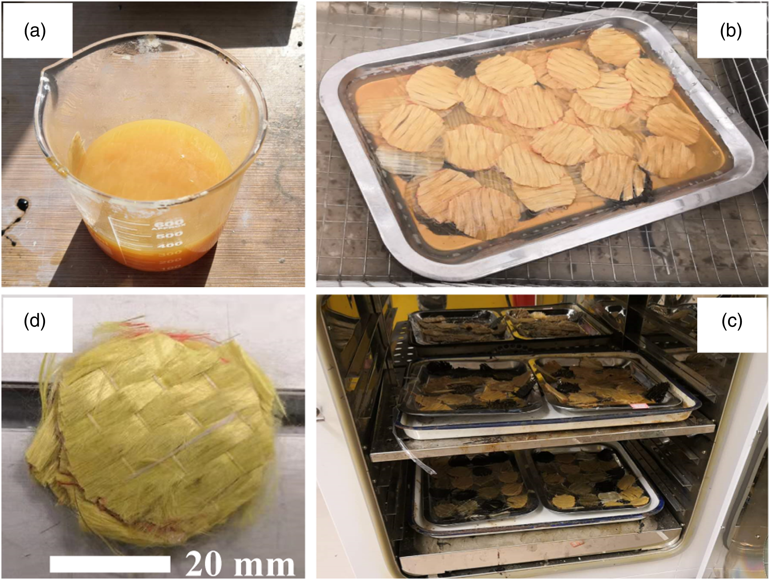
SEM images of neat FRP and FRP-STF composites are shown in Figure 3. Compared to Figure 3(a) and (d), Figure 3(b) and (e), and Figure 3(c) and (f), respectively, the size of the nanoparticles adhering to the filaments is significantly smaller than the filament diameter. Moreover, Figure 3(d)–3(f) demonstrates a substantial distribution of SiO2 nanoparticles on the filament surface and their filling of gaps in the FRP-STF composites. Therefore, the successful incorporation of STF in FRP composites is indicated, which is expected to result in excellent mechanical performance owing to the enhanced fiber bonding facilitated by the particles. Additionally, Figure 3 reveals that BFRP exhibits a larger fiber spacing than CFRP,
37
which has the tightest spacing, followed by AFRP. Therefore, there will be a significant variation in the overall stress experienced by the three types of fibers. SEM of neat AFRP, BFRP, CFRP, and its corresponding STF composites: (a) AFRP; (b) BFRP; (c) CFRP; (d) AFRP-STF; (e) BFRP-STF; (f) CFRP-STF.
Split Hopkinson pressure bar impact testing
Figure 4 illustrates the SHPB apparatus used in this test. The test system includes a loading device, a pressure bar device, and a data acquisition system.
24
The pressure bar device comprises an incident bar, a transmission bar, an absorption bar, and an end-damping device. All rods used in this test are made of aluminum and have a diameter of 40 mm. The rods have an elastic modulus of 70 GPa, 2.71 g/cm3 density, and a wave velocity of 5082.3 m/s. Both the incident rod and transmission shaft have a length of 1800 mm. High strain impact test setup: (a) SHPB system; (b) strain gauges; (c) test specimen; (d) air pressure device.
Additionally, the impact rod is 300 mm long to facilitate the control of the loading wave. The loading device is powered by high-pressure purified nitrogen, and the strain rate corresponding to the air pressure is determined using the data acquisition system. The strain rates employed in this test are 3800 s−1, 4100 s−1, 5100 s−1, and 6100 s−1. Considering the influence of the mass fraction of STF (0%, 15%, and 20%), there are twelve specimens for each type of FRP, resulting in 36 specimens being tested in this study.
Results and discussion
Impact response under high strain rate
Figure 5 presents the stress-strain responses of AFRP-STF, BFRP-STF, and CFRP-STF specimens with varying mass fractions of STF under impacts of 3800 s−1 and 6100 s−1. Figure 5(a) illustrates the significant impact of the STF composite on the stress response of AFRP, BFRP, and CFRP under an impact of 3800 s−1. Compared to pure AFRP, the stress behavior of AFRP-STF remains largely unchanged after the STF’s addition. However, when 20% STF is used, the stress peak of AFRP increases from 120.8 MPa (pure AFRP) to 161.7 MPa (AFRP-20% STF), indicating a 33.9% increase. In contrast, the stress response of BFRP experiences significant changes after incorporating STF. Specifically, when using 20% STF, the stress peak increases by 58.9% compared to pure BFRP. Although the effect of 15% STF on the stress peak is less significant than that of 20% STF, it exhibits favorable ductility characteristics in stress behavior. However, unlike AFRP-STF and BFRP-STF, the incorporation of STF significantly reduces the stress peak of CFRP by 40.4% (with 15% STF) and 29.0% (with 20% STF) at an impact speed of 3800 s−1. This reduction may be attributed to the lubricating behavior of STF at low strain rates.
38
The SiO2 nanoparticles in STF form a thin film through physical adsorption on the surface of fibers, promoting fiber separation. Additionally, spherical SiO2 nanoparticles, filled with micropores and located on the fiber surface, play a crucial role in fiber repair and reducing friction between fibers.39,40 Stress response of AFRP-STF, BFRP-STF, and CFRP-STF at strain rates of 3800 s-1 and 6100 s-1: (a) AFRP-STF; (b) BFRP-STF; (c) CFRP-STF.
Figure 5 further shows that the incorporation of STF greatly enhances the stress response of pure AFRP, BFRP, and CFRP when subjected to an impact strain rate of 6100 s−1. For example, at a mass fraction of 15% of STF, the stress peaks of the three variations of FRP experience substantial increases of 29.0%, 42.7%, and 22.4%, respectively. However, when the mass fraction of STF is increased from 15% to 20%, the effect on increasing the stress peak of the three types of FRP is only 5.5%, −20.0%, and 1.7%, respectively. Although the impact of increasing the stress peak is considerably diminished when compared to a strain rate of 3800 s−1, it can be inferred that 15% STF and 20% STF effectively fulfill their roles as strengthening agents under high strain rate impact.
Figure 6 illustrates that the strain energy absorption performance of AFRP and BFRP composites is greatly enhanced when combined with STF at an impact rate of 3800 s−1. Specifically, BFRP’s energy absorption capacity is increased by 257.5% and 169.3%, respectively, compared to pure BFRP when the STF mass fraction is 15% and 20%. With a mass fraction of STF at 20%, the energy absorption capacity of AFRP increases by more than 226.8%, leading to a shift in the energy absorption mode. Based on the data from Figure 6(a), the energy absorption versus time curve of AFRP-STF no longer exhibits a significant decline segment. This change is mainly attributed to the adherence of SiO2 nanoparticles to fibers and their gathering through fiber deformation, blocking the transmission of stress waves and enabling a continuous increase in the energy absorption capacity of AFRP-STF. In contrast, pure AFRP experiences a decrease in energy absorption capacity over time as stress waves directly pass through its fibers. A similar phenomenon is observed in the energy absorption versus time curves of BFRP-STF and CFRP-STF. As the stress response of CFRP-STF is lower than that of pure CFRP, the energy absorption capacity for CFRP-STF is weaker than that of pure CFRP in its energy absorption versus time curve. However, an increase in the mass fraction of STF enhances the energy absorption capacity of CFRP-STF from 23.7 J to 60.7 J, an increase of approximately 1.6 times. Energy absorption performance of AFRP-STF, BFRP-STF, and CFRP-STF at strain rates of 3800 s-1 and 6100 s-1: (a) AFRP-STF; (b) BFRP-STF; (c) CFRP-STF.
At a strain rate of 6100 s−1, the energy absorption capacity of AFRP-STF, BFRP-STF, and CFRP-STF is considerably higher than that at 3800 s−1. The energy absorption capacity of AFRP, BFRP, and CFRP significantly improves upon incorporating STF into the composite. For instance, with an STF mass fraction of 20%, the energy absorption capacity of the three FRPs increases by 34.2%, 54.7%, and 226.1%, respectively. This could be attributed to the FRP becoming softer and experiencing a substantial increase in fracture strain after impregnation with STF, thus significantly enhancing the energy absorption capacity. Additionally, comparing the three FRPs, it is evident that CFRP-STF demonstrates the most significant improvement in energy absorption at 6100 s−1. It reaches 214.0% and 226.1% after incorporating 15% STF and 20% STF into the composite. This improvement capability is 2.8 times greater than AFRP-15% STF and 3.2 times greater than BFRP-15% STF. It increases to 6.6 times and 4.1 times as the mass fraction of STF increases to 20%. This may be attributed to the increase in the number of SiO2 nanoparticles as the mass fraction of STF increases, facilitating greater contact between fibers over a larger area and thus resulting in increased frictional force.
The field photos of AFRP-20% STF, BFRP-20% STF, and CFRP-20% STF before impact, after a 3800 s−1 impact, and after a 6100 s−1 impact, respectively, are shown in Figure 7. From Figure 7(a)–(c), it is evident that the surface of the untested specimen has a weak reflection, indicating the successful combination of AFRP, BFRP, and CFRP with STF, respectively. Figure 7(d)–(f) reveals indentations on the surface of AFRP-20% STF, BFRP-20% STF, and CFRP-20% STF, with noticeable fiber fracture phenomena observed in the periphery and middle after a 3800 s−1 impact. Compared to AFRP-20% STF and CFRP-20% STF, BFRP-20% STF exhibits more severe damage, characterized by evident fiber fracture and somewhat loose overall integrity of the specimen. However, the integrity of all three specimens mentioned above remains intact. Figure 7(g)–(i) indicate that both AFRP-20% STF and CFRP-20% STF, as well as BFRP-20% STF, have sustained damage under a 6100 s−1 impact. These figures show that AFRP-20% STF exhibits extensive loosening behavior, BFRP-20% STF is completely broken, and only a small amount of fiber remains in CFRP-20% STF. Fields photos of specimens: (a)–(c) for AFRP-20% STF, BFRP-20% STF and CFRP-20% STF before impact, respectively; (d)–(f) for AFRP-20% STF, BFRP-20% STF and CFRP-20% STF after impact at 3800 s−1, respectively; (g)–(i) for AFRP-20% STF, BFRP-20% STF and CFRP-20% STF after impact at 6100 s−1, respectively.
Effect of mass fraction of shear thickening fluid
Investigating the mass effect involves calculating the absorbed strain energy per unit density for different FRP materials. From Table 1, the densities for AFRP, BFRP, and CFRP are 1.45 × 10³, 1.76 × 10³, and 1.80 × 10³ kg/m3, respectively. Figure 8 illustrates the strain energy absorption peaks normalized by the density of AFRP-STF, BFRP-STF, and CFRP-STF at strain rates of 3800 s−1 and 6100 s−1. Absorbed energy per unit density of AFRP-STF, BFRP-STF, and CFRP-STF: (a) 3800 s-1; (b) 6100 s-1.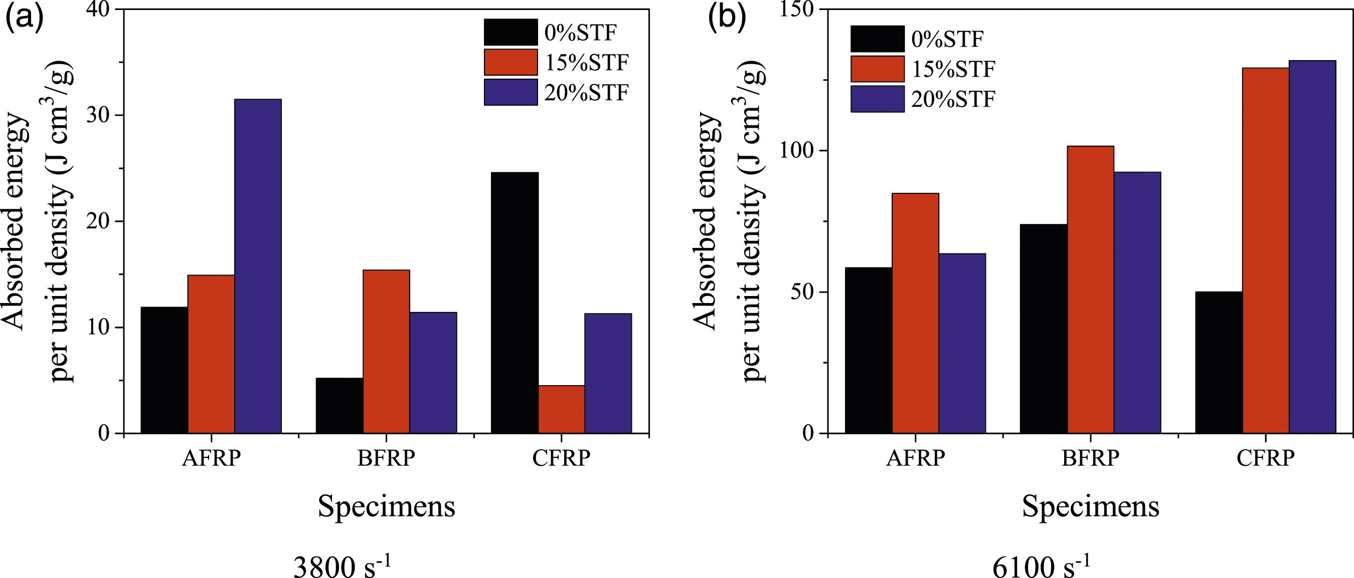
From Figure 8(a), it is evident that at lower strain rates, STF is beneficial in enhancing the energy absorption capacity of AFRP and BFRP but harms CFRP. For instance, AFRP-15% STF and BFRP-15% STF exhibit increases in energy absorption capacity of 25.2% and 34.2% compared to pure AFRP and BFRP, respectively, while CFRP-15% STF shows a decrease of 40.4%. Figure 8(a) further highlights that increasing the mass fraction of STF proves advantageous for improving the energy absorption capacity of AFRP-STF and CFRP-STF, particularly AFRP-20% STF, which exhibits a 35.1% increase compared to AFRP-15% STF, whereas CFRP-20% STF demonstrates only a 19.1% increase. The observed phenomena can be attributed to the elastic moduli of the three FRP types. Table 1 reveals the elastic moduli of CFRP (210 GPa), AFRP (110 GPa), and BFRP (91 GPa) in descending order. Under a 3800 s−1 impact, the high elastic modulus of CFRP prevents substantial deformation, consequently inhibiting friction generation between CFRP fibers due to limited contact. Additionally, considering the role of nanoparticles in enhancing tribological properties,38–40 the impact of STF on the energy absorption of CFRP becomes negative. For the AFRP and BFRP, AFRP and BFRP experience significant deformation due to their lower elastic moduli. SiO2 nanoparticles adhered to fibers promote extensive contact and generate higher frictional forces between AFRP or BFRP fibers.17,41–44 Consequently, this frictional force enables more fibers to collectively participate in resisting impact loads, significantly improving the energy absorption capacity of AFRP or BFRP.
Figure 8(b) illustrates that as the strain rate increases to 6100 s−1, the energy absorption capacity of BFRP-STF and CFRP-STF surpasses that of AFRP-STF, particularly in the case of CFRP-STF where the energy absorption capacity of CFRP-15% STF is approximately 1.2 times higher than that of AFRP-15% STF. Additionally, the addition of STF dramatically enhances the energy absorption capacity of all three types of FRP, such as AFRP-15% STF, BFRP-15% STF, and CFRP-15% STF, with energy absorption capacity increases of 76.2%, 67.1%, and 214.0% compared to pure AFRP, BFRP, and CFRP, respectively. However, an increase in the mass fraction of STF does not lead to a significant or even positive effect on the further improvement of the mechanical properties of the three types of FRP, such as a 23.8% decrease in the energy absorption capacity of AFRP-20% STF.
Strain rate effect
Using AFRP-20% STF, BFRP-20% STF, and CFRP-20% STF as examples, the impact of strain rate on the mechanical properties of these FRP-STF materials is illustrated in Figure 9. The results indicate that strain rate significantly influences the stress peak and energy absorption capacity in FRP-STF. The strain rate effect is relatively consistent across the three FRP-STFs. However, as the strain rate increases from 3800 s−1 to 6100 s−1, the stress peak experiences an increase of 95.1%, 117.0%, and 157.1%, respectively. Among AFRP-STF and CFRP-STF, the maximum increase in stress peak due to strain rate occurs when it rises from 3800 s−1 to 4100 s−1, with rates of 65.2% and 81.7%, respectively. Furthermore, Figure 9(b) reveals that the strain energy absorption capacity in AFRP-STF displays less sensitivity to strain rate increases than BFRP-STF and CFRP-STF. Notably, when the strain rate increases from 5100 s−1 to 6100 s−1, the energy absorption capacity demonstrates increases of 107.5% and 102.6% in BFRP-STF and CFRP-STF, respectively, representing 3.4 times and 3.3 times the increase compared to AFRP-STF. Importantly, throughout the entire strain rate increase process, the energy absorption capacity of AFRP-STF only showed a factor of 1.0 increase, whereas BFRP-STF and CFRP-STF saw increases of 7.1 and 10.7, respectively. Stress peak and absorbed energy of AFRP-20%STF, BFRP-20%STF, and CFRP-20%STF under different strain rates: (a) stress peak; (b) absorbed energy.
Conclusions
This study investigated the effect of STF on the improvement of mechanical properties of FRPs (including AFRP, BFRP, and CFRP) under high strain rate impact. SHPB tests were conducted on twelve pure FRP and 24 FRP-STF specimens, respectively. The results of the SHPB tests demonstrated that the addition of STF improved the mechanical properties of these FRPs under high strain rate impacts, including stress response and strain energy absorption. However, the extent of improvement varied among different FRP types. At lower strain rates, AFRP-20% STF displayed superior stress response performance, while BFRP-20% STF exhibited a significant increase in stress peaks. The tests conducted at higher strain rates showed no significant difference in the stress peaks of the three types of FRP-STF. However, CFRP-STF exhibited the highest strain energy absorption capacity, and increasing the mass fraction of STF had a greater impact on strain energy absorption capacity than stress peaks.
The investigation of strain energy absorption per unit density indicates that STF also significantly influences the mechanical properties of FRPs. However, this impact depends on the FRP’s elastic modulus and the loading high strain rate. Overall, at lower strain rates, AFRP-STF demonstrates optimal mechanical properties, and increasing the mass fraction of STF can significantly enhance the energy absorption capacity of AFRP-STF. Conversely, under higher strain rates, CFRP shows a more effective reinforcement effect from STF, although the increase in STF mass fraction has a negligible impact on this reinforcement effect. Additionally, AFRP-STF, BFRP-STF, and CFRP-STF all exhibit significant strain-dependent stress response and energy absorption capacity. Consequently, this study suggests prioritizing AFRP-STF in environments characterized by lower strain rate impacts, while CFRP-STF should be given priority in environments with higher strain rate impacts.
While STF enhances the mechanical properties of FRP under high strain rate impact, its rheological properties are highly susceptible to changes in environmental temperature. Consequently, it becomes imperative to examine the influence of environmental temperature on the mechanical properties of FRP-STF under high strain rate impact. Additionally, future endeavors should focus on developing commercially viable FRP-STF products based on the identified mechanical properties of FRP-STF.
Footnotes
Authors’ contributions
Z.H. contributed significantly to the analysis and manuscript preparation. J.C. experimented; F.Z. performed the data analyses. M.W. contributed to the conception of the study; helped perform the analysis with constructive discussions. W.G. performed the experiment and data analyses and wrote the manuscript. All authors reviewed the manuscript.
Declaration of conflicting interests
The author(s) declared no potential conflicts of interest with respect to the research, authorship, and/or publication of this article.
Funding
The author(s) disclosed receipt of the following financial support for the research, authorship, and/or publication of this article: The authors acknowledge financial support from the Hunan Provincial Department of Education Project [grant number 18C0562] and supported by the Natural Science Foundation of Zhejiang Province [grant number LY23E080011].
Ethical Statement
Data availability statement
The raw/processed data required to reproduce these findings cannot be shared as the data also forms part of an ongoing study. The relevant data can be made available on request.