
Abstract
This paper reports an experimental and numerical study on the spherical indentation behavior of three-dimensional (3D) warp-knitted mesh fabrics. A full-size finite element (FE) model of a typical 3D mesh fabric is established at the yarn level based on the realistic monofilament architecture from micro-computed tomography (μCT) scanning and verified with experiments. The structural change of the fabric in the spherical indentation process is quantitatively analyzed in terms of fabric global deformation, local deformation, mesh deformation, and spacer monofilament deformation from the FE simulation. The numerical results show that the fabric shrinks walewise and expands coursewise from the spherical indentation of the continuous intermeshed monofilament architecture, showing counterintuitive partial auxeticity. The coursewise symmetry and walewise asymmetry of the 3D mesh fabric produce relatively symmetrical coursewise deformation and asymmetrical walewise deformation under spherical indentation. The symmetrical coursewise deformation includes even widening, good fitting of the indenter, and almost identical mesh sizes in the coursewise direction. Walewise asymmetry leads to uneven shortening, inferior fitting of the indenter, and considerably varied mesh sizes in the walewise direction. Spacer monofilaments in different positions relative to the spherical indenter have different deformations. The closer to the indenter, the greater bending and twisting of the spacer monofilament. The spacer monofilament knitted earlier of the tested fabric has smaller deformation than that knitted later due to the walewise asymmetry. The coursewise symmetry and walewise asymmetry of the inhomogeneous 3D mesh fabric structure result in a highly nonlinear spherical indentation behavior.
Introduction
Three-dimensional (3D) mesh fabrics are special warp-knitted spacer fabrics with two meshed outer layers,1–3 as shown in Figure 1. The unique 3D mesh structure endows the fabric not only with good compression resistance and resilience, but also with excellent ventilation even under compression.4,5 Recently, 3D mesh fabrics have found increasing applications as the cushion and ventilation layers in automotive seat ventilation systems, wheelchairs, and medical mattresses.6–9 In these applications, 3D mesh fabrics are compressed by different parts of the human body with different curvatures. This kind of compression is close to spherical indentation rather than flatwise compression. The complex loading and boundary conditions imposed on fabrics in those applications and the highly heterogeneous and discontinuous fabric structures result in an extremely intricate deformation mechanism. As a result, the development of 3D mesh fabrics to provide excellent cushion and ventilation must take spherical indentation into account. A typical 3D mesh fabric.
Previous studies have focused mainly on the flatwise compression behavior of spacer fabrics.10–17 It has been found that spacer fabrics have the key features of a cushioning material such as polyurethane foams and have three distinct stages under flatwise compression, described as linear elasticity, plateau, and densification in succession.10,11 The three compression stages are attributed to post-buckling, torsion, shear, rotation, and contacts among the spacer monofilaments, as well as contacts between the spacer monofilaments and the outer layers.11,14
The deformation behaviors of spacer fabrics under curved indentation and flatwise compression loadings are different. Some efforts have been made to study the curved indentation behavior of spacer fabrics by using experimental, analytical, or numerical methods. Guo et al. 17 found that the spacer fabric with a closed surface structure and coarser spacer yarns has a lower peak force and a higher energy absorption capacity under compression of the hemispherical impact. Liu et al.18,19 tested a typical warp-knitted spacer fabric against impact following the European Standard BS EN 1621-1:1998 in hemispherical form and concluded that increasing the curvature of the fabric reduces energy absorption and force attenuation. It has also found that compression resistance under spherical indentation increases with increasing the spherical indenter radius and decreases with increasing the fabric thickness.20–22 Several finite element (FE) models have been developed by simplifying the outer layers of spacer fabrics into uniform hexagonal mesh structures 23 or homogeneous plates 24 and the spacer monofilaments as discrete slender elastic rods with an identical spatial form.23,24 However, the monofilament architecture of spacer fabrics is intermeshed and continuous.2,3,25 The homogeneous and discrete assumptions in previously reported FE models cannot reflect the authentic deformation of spacer fabrics under spherical indentation. The mesoscopic structural deformation of spacer fabrics under spherical indentation is not yet clear.
This work aims to reveal the deformation mechanism of 3D mesh fabrics under spherical indentation through experiments and numerical simulations. A typical 3D mesh fabric is used here to build a full-size FE model at the yarn level. The global and local structural deformation of the fabric, as well as the deformation process of the meshes on the surface and the spacer monofilaments, are quantitatively analyzed. A thorough understanding of the complex spherical indentation behavior of 3D mesh fabrics is achieved from this work.
Experimental and modeling
Fabric details
Chain notations and yarn materials used for the 3D mesh fabric.

Test methods
Spherical indentation test
The spherical indentation test was conducted on a YG028 universal mechanical tester (Dahe Instrument Co., Ltd., Ningbo, Zhejiang, China). The 3D mesh fabric was cut into square specimens of 100 mm × 100 mm and placed on a square platen as shown in Figure 2. A spherical indenter with a diameter of 38 mm was used to compress the fabric at a speed of 10 mm/min up to an indentation displacement of 10 mm in an environment of 20°C and 65% relative humidity. Spherical indentation test.
Tensile tests
To obtain input data for the analysis, the polyester multifilament and monofilament yarns unraveled from the fabric were tested on the same universal mechanical tester according to the British standard BS EN 13,895:2003 in a standard environment of 20°C and 65% humidity. The gauge, pretension, and speed for the tensile tests are 250 mm, 0.05 ± 0.005 cN/dtex, and 250 mm/min, respectively. Ten samples were tested for both multifilament and monofilament yarns.
Finite element analysis
Finite element model
The fabric has a periodic structure, and a unit cell was reconstructed by μCT scanning in our previous work.
25
The unit cell was imported into the LS-PrePost to establish a FE model. As shown in Figure 3(a), the length, width, and height of the unit cell are 14.8 mm, 9.8 mm, and 10.5 mm, respectively. The unit cell consists of two polyester monofilaments and each monofilament was divided into 2000 integrated beam elements in 3×3 Gauss quadrature. Then a full-size FE model containing 7 units in the X direction (walewise) and 10 units in the Y direction (coursewise) was established, as shown in Figure 3(b). FE model for spherical indentation of 3D mesh fabric: (a) unit cell; (b) full-size model.
The fabric model is placed on a rigid platen. A spherical indenter with a diameter of 38 mm is built above the fabric model and divided into 15,000 shell elements. An indentation displacement of UZ = −10 mm is applied to the indenter to simulate the spherical indentation process, while its other translational and rotational degrees of freedom are constrained. The interaction among spacer monofilaments and between the fabric and the indenter is detected with single surface contact (*CONTACT_AUTOMATIC_GENERAL), and the coefficients of dynamic and static friction are 0.27 and 0.28, respectively. 12
Material properties
The spherical indenter was assigned with rigid material model [*MAT_RIGID (020)] with structural steel’s properties (ρ = 7.85 g/cm3; E = 2 × 10⁵ MPa; v = 0.3). Only the monofilament yarns in the fabric were reconstructed, and discrete spring elements are used here to physically simulate the constraints on monofilament yarns provided by multifilament yarns, as illustrated in Figure 3(a). Spring I is used to connect two intermeshed monofilament loops with four springs to play the role of multifilament loops, while spring II is used to connect the two monofilaments together as multifilament inlays. The chain yarn and the inlaid yarn are the same polyester multifilament. Therefore, the tensile load–displacement relationship of the polyester multifilament yarns unraveled from the fabric as plotted in Figure 4(a) was input into a nonlinear spring model for both spring I and spring II. Tensile properties of polyester filament unraveled from the fabric: (a) multifilament; (b) monofilament.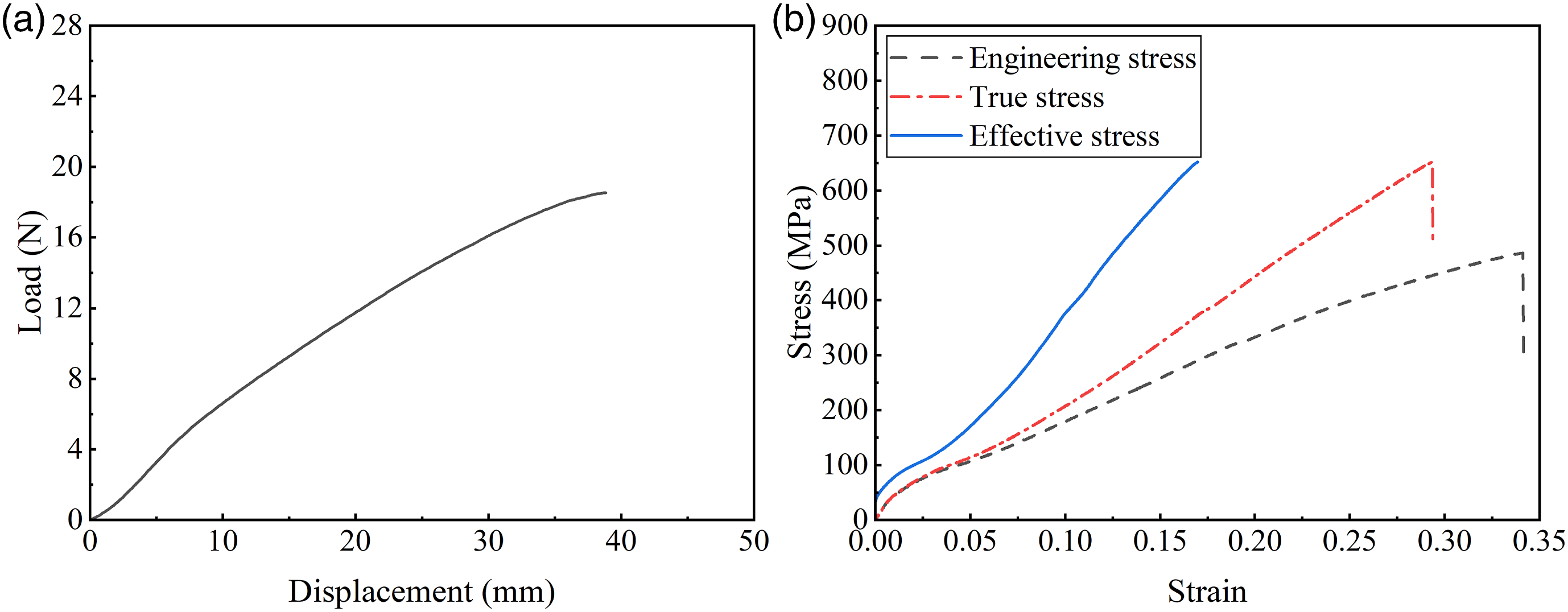
The tensile stress–strain curve of the polyester monofilament unraveled from the fabric is shown in Figure 4(b). An isotropic linear elasto-plastic material model [*MAT_PIECEWISE_ LINEAR_PLASTICITY (024)] is selected from the LS-DYNA material library to simulate the constitutive behavior of the monofilament. The elastic modulus and yield stress are calculated from the true stress–strain curve, which are 5268.7 MPa and 36.2 MPa, respectively. The effective stress–strain curve as plotted in Figure 4(b) is used to describe the plastic behavior and also input into the material model. In addition, the density and Poisson's ratio are 1.38 g/cm3 and 0.3, respectively.
Results and discussion
Model verification
The full-size FE model used to numerically simulate the spherical indentation process of the fabric was solved using the explicit solver LS-DYNA. Experimentally captured deformations under indentation at displacements of 2, 4, 6, 8 and 10 mm, along with the original geometry, are compared with the simulated deformation displacement contour plots of the fabric along the Z direction in Figure 5. To make a good presentation, the Z-displacement contour plot fringe range is fixed from −2 to 4 mm. The simulations and experiments demonstrate a similar spherical indentation process of the fabric. At 2 mm displacement, only the part of the fabric in contact with the indenter is deformed, and the rest of the fabric remains unchanged. As the displacement increases to 4 mm, the part of the fabric that does not come into direct contact with the indenter also gradually deforms. When the displacement reaches 10 mm, an obvious upward warping deformation is observed at the edges of the fabric. Spherical indentation process of 3D mesh fabric at different displacements: (a) 0 mm; (b) 2 mm; (c) 4 mm; (d) 6 mm; (e) 8 mm; (f) 10 mm.
To analyze the upward warping deformation process, eight nodes (N1–N8) are selected from the top outer layer edges as annotated in Figure 5(a). The upward height–indentation displacement relationships of the eight nodes during indentation are plotted in Figure 6. In the initial stage of spherical indentation, there is no upward warping, since the compression load has not been transferred to the fabric edges. As the indentation displacement increases, the upward warping deformations of the eight nodes are different. N5 starts to move upward when the indentation displacement is 1.5 mm, while N1 and N4 move upward at a displacement of 2.5 mm. N3, N6 and N8 appear initially downward and move upward when the displacement reaches 3.5 mm. Specially, N2 and N7 barely warping upward throughout the indentation process. When the indention displacement is 10 mm, N4 and N5 have the greatest upward heights of 3.8 and 5.2 mm, N2 and N7 have the lowest warping heights of 0.1 and 0.2 mm, and the warping heights of N1, N3, N6 and N8 are ranging from 1.6 to 2.3 mm. This complex diversity is due to the highly heterogeneous and discontinuous fabric structure. The monofilaments in the fabric are continuously connected by intermeshing loops and tightly bound by multifilament chain yarns in the walewise direction, while the adjacent monofilament wales in the coursewise direction are partially connected with inlaid yarns. Compression loads can therefore be transferred quickly and directly walewise but hardly transferred coursewise. This results in greatest warping deformation of N4 and N5 in the middle of the two coursewise edges, while lowest warping deformation of N2 and N7 in the middle of the two walewise edges. The warping heights of the four vertices N1, N3, N6 and N8 are within those of the midpoints of the two walewise edges and the two coursewise edges. The upward height of the eight nodes from the edges of the fabric model during spherical indentation.
The simulated and experimental indentation load–displacement curves are plotted in Figure 7. The FE prediction is found to be in agreement with the experimental data, so the FE model is validated. The flatwise compression behavior of spacer fabrics can be divided into linear elasticity, plateau, and densification stages in succession.11,12 However, the spherical indentation load–displacement curve has no obvious plateau stage. In flatwise compression, all spacer monofilaments bear the compression load at the same time. By contrast, in spherical indentation, the number of spacer monofilaments that support the indentation load increases gradually, and the displacements of spacer monofilaments are also different. The detailed deformation of the 3D mesh fabric under spherical indentation is discussed in terms of fabric global deformation, local deformation, mesh deformation, and spacer monofilament deformation below. Simulated and experimental indentation load–displacement curves of the 3D mesh fabric.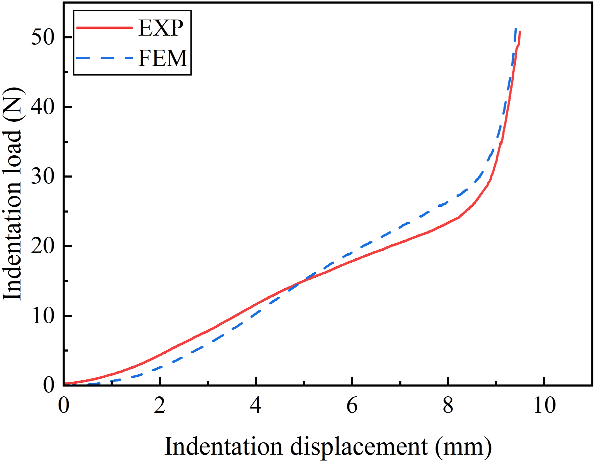
Fabric global deformation
The deformation displacement contour plots of the fabric along the X direction (walewise) and Y direction (coursewise) are shown in Figures 8 and 9, respectively. The fabric shrinks walewise and expands coursewise under spherical indentation. Displacement in X direction (walewise) at different displacements: (a) 0 mm; (b) 2 mm; (c) 4 mm; (d) 6 mm; (e) 8 mm; (f) 10 mm. Displacement in Y direction (coursewise) at different displacements: (a) 0 mm; (b) 2 mm; (c) 4 mm; (d) 6 mm; (e) 8 mm; (f) 10 mm.

The red area in Figure 8(a)–(f) represents positive displacements along the X direction, while the blue area is just the opposite. It can be found that the fabric shrinks walewise and the shrinkage is unsymmetrical between the left and right parts. The left part of the fabric that is knitted first shrinks less than the right part. Similarly, the red area in Figure 9(a)–(f) represents positive displacements along the Y direction, while the blue area is just the opposite. Unlike the shrinkage in the walewise direction, the expansion in the coursewise direction is almost symmetrical, which indicates that the fabric has a certain coursewise symmetry. In fact, the 3D mesh fabric is knitted in the walewise direction, so all the monofilament wales are almost identical. This structural feature gives the fabric coursewise symmetry and walewise asymmetry.
To quantitatively analyze the shrinkage in the walewise direction and the expansion in the coursewise direction, the intermediate column (lx) and row (ly) of the fabric are selected as shown in Figure 8(a) and Figure 9(a), respectively. Their strains, namely εx and εy, are calculated and plotted in Figure 10, respectively. The 3D mesh fabric has partial auxeticity that exhibits a negative Poisson's ratio in the walewise direction and a positive Poisson's ratio in the coursewise direction under spherical indentation. The leftmost and rightmost extremities are changed from straight to reentrant, while the topmost and bottommost extremities are convex after spherical indentation. When the indentation displacement is 10 mm, εx is −4.6% and εy is 0.9%. Hence, the 3D mesh fabric behaves differently than homogeneous polymeric foams that expand and shrink in all directions under flatwise compression and spherical indentation, respectively. Fabric planar deformation of the intermediate column and row at different indentation displacements.
Fabric local deformation
The fabric area in direct contact with the spherical indenter plays a key role in resisting spherical indentation loading. Its deformation and interaction with the indenter are of great importance to reveal the spherical indentation mechanism of the fabric.
Figure 11 presents the deformation of the central region of the fabric during spherical indentation from different perspectives. It is shown that when the indentation displacement increases, the distortion area progressively increases and the contact area between the indenter and the fabric also increases. Eventually, the top outer layer of the fabric changes from flat to hemispherical. The deformation modes in the walewise and coursewise directions are different. In the walewise direction, that is, in Figure 11(c), there is a gap between the fabric and the indenter, while in the coursewise direction as shown in Figure 11(d), the fabric is always closely fitted to the indenter during the indentation process. This phenomenon is due to the fabric coursewise symmetry and walewise asymmetry. The monofilament architecture is continuous walewise and separate coursewise. Wales of monofilament are connected by multifilament inlays. The fabric is hard to deform walewise and easy to deform coursewise, so it can easily fit the indenter in the coursewise direction. The simulation clearly discloses the orthogonal anisotropy of the 3D mesh fabric. Fabric local deformation at different displacements from different perspectives: (a) perspective view; (b) top view; (c) front view; (d) left view.
Mesh deformation
Unlike flatwise compression with no obvious deformation of the outer layers, the meshes deform largely under spherical indentation, as illustrated in Figure 11. A part of the deformed meshes in the top outer layer near the indenter at different displacements are selected and shown in Figure 12 to quantitatively analyze the mesh deformation. The initially identical meshes deform differently upon spherical indentation. Mesh deformation of fabric at different displacements: (a) 0 mm; (b) 2 mm; (c) 4 mm; (d) 6 mm; (e) 8 mm; (f) 10 mm.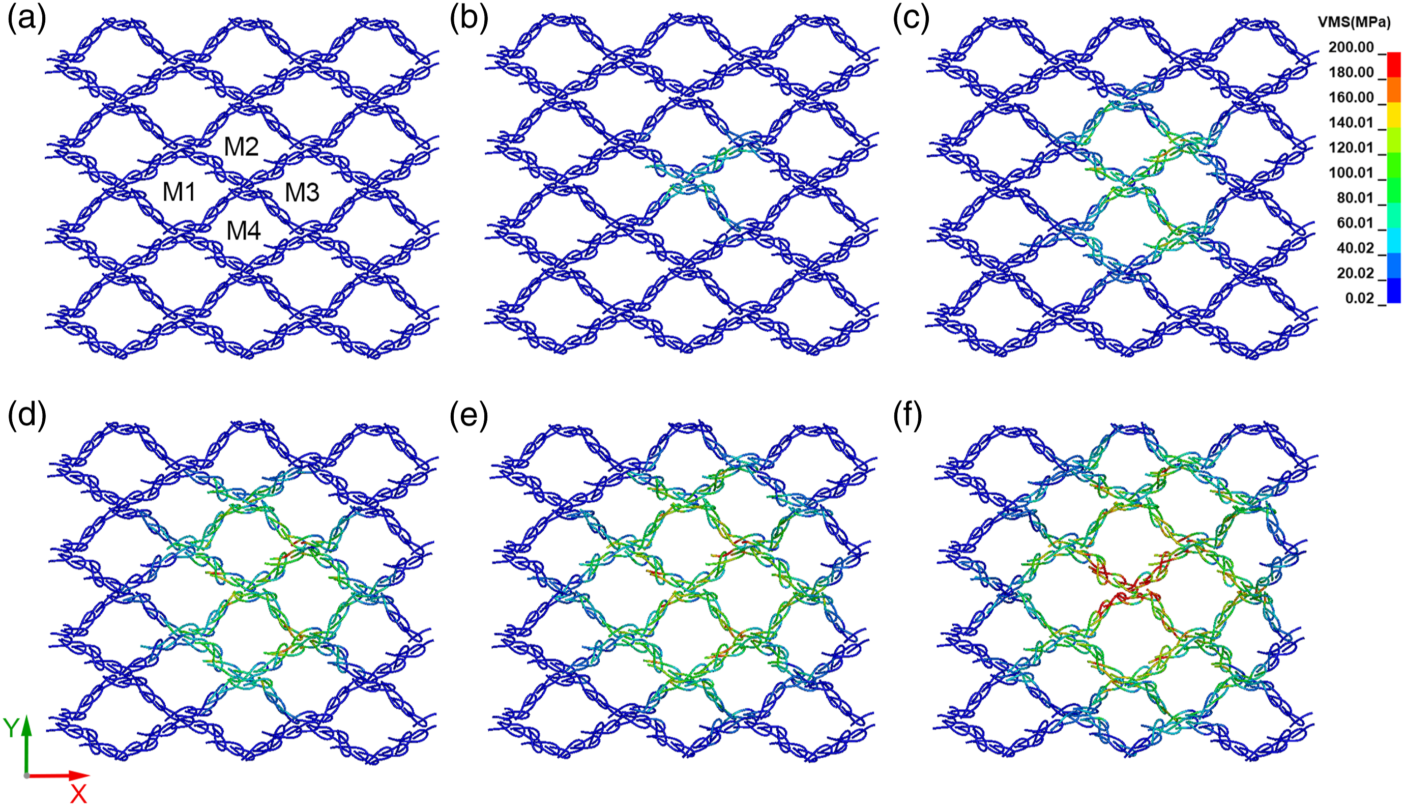
Four meshes (M1–M4) are selected as annotated in Figure 12(a). Their widths, lengths, and enclosed areas are measured and plotted against indentation displacement in Figure 13. The walewise shrinkage and coursewise expansion of the four meshes are different. M1 knitted earlier and located on the left side of the indenter shrinks and widens less than M3 knitted later and located on the right side. The increase in the enclosed area of M3 is much higher than that of M1. By contrast, M2 and M4 knitted simultaneously shorten first and then lengthen, but they widen consistently throughout the indentation process. The enclosed areas of M2 and M4 first decrease at 2 mm displacement and then increase. The interaction between the indenter and the meshes involves complex contact and slipping movements. The fabric coursewise symmetry and walewise asymmetry produce variations in deformation of meshes in different relative positions under spherical indentation. Mesh sizes at different displacements: (a) length; (b) width; (c) enclosed area.
Spacer monofilament deformation
The deformation of the meshes changes the spatial configuration of the spacer monofilaments. In addition, the spacer monofilaments at different positions are subjected to different indentation displacements. Consequently, the spacer monofilaments undergo intricate post-buckling deformation, resulting in a 3D highly nonlinear and inhomogeneous structure.
Taking a monofilament wale from the central region of the fabric as an example, the deformation process of the spacer monofilaments under spherical indentation is demonstrated in Figure 14. Upon indentation, the spacer monofilaments in the middle begin to bend and deform, and gradually spread to both ends as the displacement increases. The intermediate spacer monofilament always has the greatest deformation. At the end of the indentation process, the lower end of the wale of spacer monofilaments remains in the same horizontal line, but the upper end becomes a hemisphere-like curve. A wale of monofilament contains three units in the central region at different displacements: (a) 0 mm; (b) 2 mm; (c) 4 mm; (d) 6 mm; (e) 8 mm; (f) 10 mm.
The spacer monofilaments in Figure 14 belong to three identical units, so the spacer monofilaments in the same position in the units have identical initial spatial configurations. However, because of the difference in distance from the indenter and walewise asymmetry, there are no spacer monofilaments of the same shape after the spherical indentation process. A quantitative analysis of the spatial deformation of spacer monofilaments with the same initial spatial configuration is performed to reveal the spherical indentation mechanism of spacer fabrics.
Three spacer monofilaments (S1–S3) of the three units are selected in the same position as annotated in Figure 14(a) for the quantitative analysis. Their deformed geometries are shown in Figure 15(a)–(c). In the indentation process, the bottom end of the spacer monofilaments remains almost fixed, while the top end gradually moves downward. The displacements and boundary conditions applied to the three spacer monofilaments are different, resulting in different deformation modes. S1 is far from the indenter, so its deformation is minimal. By contrast, S2 is almost located in the center of the indenter, so it has the biggest deformation. Deformation of spacer monofilaments at different displacements: (a) geometry, (d) curvature, and (g) torsion of S1; (b) geometry, (e) curvature, and (h) torsion of S2; (c) geometry, (f) curvature, and (i) torsion of S3.
Curvature and torsion are highly sensitive indicators of deviation from straight lines and plane curves. The curvature and torsion of the three monofilaments along the length are used to quantify the local changes in the spacer monofilaments. Figure 15(d)–(f) presents the curvature curves of S1–S3, respectively, and their corresponding torsion curves are plotted in Figure 15(g)–(i).
The curvature of the initial spacer monofilament fluctuates throughout its length as shown in Figure 15(d)–(f). More specifically, its intermediate part has a curvature lower than that of the other parts. The torsion of the initial spacer monofilament has two obvious peaks close to its two ends, and the intermediate part has a relatively constant and lower torsion. For each peak, the torsion curve changes sign twice, so the spacer monofilament changes its twisting directions four times throughout the length. Upon indentation, the spacer monofilaments begin to change their configurations. The deformations of the spacer monofilaments in different relative positions are not the same in terms of geometry, curvature, and torsion. The configuration, curvature, and torsion curves of S1 almost remain unchanged, because it is far from the indenter and not in direct contact with the indenter. S2 is located in the center of the indenter, so its height decreases as the indentation displacement increases. The configuration of S2 changes significantly with a steep increase in curvature and torsion in the intermediate part. The bending and twisting deformation of S2 is obvious and mainly localized to its intermediate part. S3 has a deformation mode similar to S2, but with smaller bending and twisting deformations due to its higher distance from the indenter. In summary, spacer monofilaments in different relative positions behave differently under spherical indentation. The closer to the indenter, the greater the degree of bending and twisting of the spacer monofilaments. In addition, the spacer monofilament knitted earlier in the tested fabric has a smaller deformation than that knitted later due to the walewise asymmetry.
Conclusions
The spherical indentation behavior of a typical 3D mesh fabric for automotive seat ventilation systems was investigated numerically and experimentally. A full-size FE model was established at the yarn level to simulate the spherical indentation process and was verified with experimental results. Global, local, mesh, and spacer monofilament deformations were analyzed. Based on the results and analyses, the following conclusions can be drawn. (1) The 3D mesh fabric has walewise shrinkage and coursewise expansion under spherical indentation, showing counterintuitive partial auxeticity. The walewise shrinkage results from shrinking of the continuous intermeshed monofilament architecture. (2) The coursewise symmetry and walewise asymmetry of 3D mesh fabric produce relatively symmetrical coursewise deformation and asymmetrical walewise deformation under spherical indentation. The part knitted earlier of the tested fabric shrinks less than that knitted later. The fabric also fits the indenter better in the coursewise direction than in the walewise direction. (3) The fabric coursewise symmetry and walewise asymmetry produce variations in deformation of meshes in different relative positions under spherical indentation. (4) The relative position of a spacer monofilament in the tested fabric determines its deformation mode under spherical indentation. The closer to the indenter, the greater the degree of bending and twisting of the spacer monofilament, and the spacer monofilament knitted earlier has smaller deformation than that knitted later due to the walewise asymmetry.
The findings suggest that the two coursewise extremities of 3D mesh fabrics should be firmly constrained to avoid upward warping and reduce asymmetrical walewise deformations to provide even ventilation and pressure relief for automotive seat ventilation systems, wheelchairs, and medical mattresses.
Footnotes
Declaration of conflicting interests
The author(s) declared no potential conflicts of interest with respect to the research, authorship, and/or publication of this article.
Funding
The author(s) disclosed receipt of the following financial support for the research, authorship, and/or publication of this article: This work was supported by the National Natural Science Foundation of China (grant number 11702062) and Textile Vision Basic Research Program (grant number J202004).