
Abstract
The complex problem of ropes (cyclic) bending over sheaves (CBOS) is considered in this article. Ropes that are used to manoeuvre and regulate sails undergo a variety of dynamic stresses which are crucial yet difficult to determine, due to the complexity of the multi-scaled braiding structure of ropes. A full dynamic Finite Element Method (FEM) simulation of a braided rope bending over a sheave is conducted with the commercial software Abaqus/Explicit, as it can capture the complex processes occurring inside the rope to high accuracy. A theoretical deduction is performed to determine the yarn paths in a 3D braided structure. Relative movement between braided yarns (including the interlacing point) are better assessed at yarn level through 3D element types instead of the traditional beam elements, as they allow to obtain an estimation of yarn-yarn displacement. Parametric studies are conducted to better understand the factors that affect the yarn sliding. The ratio between the diameter of the sheave and the rope, and the braiding angle, are found to be crucial for the relative movement, while the number of yarns and their diameters have little influence. The successful simulation process demonstrates the feasibility of modelling and analysing the complex interaction occurring in braided structures under specific boundary conditions. The calculated estimated displacement can contribute to further investigations such as the friction and heat generation problem in braided ropes. Simulation with this method can provide alternatives in predicting lifespan of braided products that cannot be easily inspected.
Introduction
To obtain ropes with better performances and cohesion, the yarns made of the filaments are arranged regularly instead of simply trussed up. Braiding is a well-known process in the textile industry for its simplicity and flexibility. The first stage of braiding production is twisting, a spiral arrangement of the filaments or fibres around the axis of the yarn. The twist keeps the filament or fibre together and forms them into yarns. Individual strands are twisted from the same way as the yarn, which gives the strands smooth surfaces. The second stage is the braiding where the strands are braided together to create the last block, the rope (Figure 1). Schematic composition of the inside of the rope.
1

The study of braiding, a structure with a long history, can be traced back to decades ago, when Backer 2 first analysed the idealized geometry of a bent yarn. Leech 3 outlined the theory of synthetic rope modelling, as well as preliminary numerical techniques and computational implementation. Wu et al. 4 primarily considered the performance of double-braided ropes, which are widely used in marine applications, and combined structural features and the constitutive behaviour of individual rope components. A circular braiding process was adapted to produce three-dimensional shapes by braiding over a contoured mandrel 5 and virtual reality modelling language (VRML) was employed as a visualization tool to simulate these geometrical models. With the aid of Visual Basic and 3DSMax Studio, Alpyildiz 6 proposed a versatile model suitable for different braid structures allowing to change the structural parameters such as braid angle, number of yarns in a set, yarn and mandrel diameter. Other research on tubular braiding was also executed,7–9 catering to different application conditions.
While braided ropes have been understood gradually, many are commonly used for their high strength, i.e., on a sailing yacht: from the regulation of sails to the docking of boats in harbours. When used to manoeuvre and regulate sails, ropes undergo a variety of dynamic stresses which leads to deterioration and possible failure. Specifically in sailing applications, the problem of cyclic bending over sheaves (CBOS) was introduced. As sailing ropes are used in incredibly challenging situations, the frequent bending behaviour due to wave action causes various problems resulting in shorter than expected rope lifespan. Over the years much research has been done on CBOS in terms of its influences in several aspects. Hobbs and Nabijou10,11 derived from first principles curvature changes in single and double helices and relative movements between the centre-lines of the strands when the rope were bent into circular arcs. They also discussed relative motion, the friction in the rope, and other parameters that affect the bending fatigue properties of wire ropes.12,13 Fatigue life was found to be significantly improved by fibre blending and with specialty coatings, 14 resulting in a new braided rope design specifically optimized for bending fatigue. Onur and İmrak 15 determined theoretically and experimentally discard lifetimes of steel wire ropes and presented a novel theoretical discard life prediction equation by using the least square method. Davies et al. 16 analysed and validated a large set of data from CBOS tests in terms of lifetime. Ning et al. 17 studied thermal failure mechanisms in CBOS and provided theoretical and experimental guidance for the design and use of fibre rope.
Due to the multi-layered feature of a braided rope, different material of yarns can be applied in one rope. Sustainable material yarns or yarns with coatings applied are selected to be the external surface for protection and insulation; the internal yarns then often are given excellent strength properties. To examine thoroughly a bent marine rope becomes tricky, especially the internal part, without cutting the rope open. Interface issues like friction, abrasion, and heat generation need to be taken into consideration as factors that influence the service life of a rope, especially in the CBOS case. One of the most determining factors is the relative displacement between the yarns as shown experimentally in Figure 2. Relative displacement between yarns when bent over a sheave as indicated with red dots on adjacent yarns that shift position.
Therefore, numerical simulation is introduced as a feasible solution, among which Finite Element Analysis (FEA) stands out for its advantages such as easier modelling of complex geometrical and irregular shapes, adaptability to meet certain specifications for accuracy, a high degree of accuracy and visualization, etc. 18 Over recent years, many other works have been done focusing on mathematical calculation of braiding structures and FEA application.19–23 Recently, a new method of mathematical and geometrical modelling of braided ropes for CBOS was proposed, of which the bent geometrical models could be used in further FEM analysis on stress distribution evaluation. 24 In most cases, research is focused on the rope when analysing the CBOS behaviour, and 2D element types such as beam or truss element are applied to represent the yarns with the consideration of investing reasonable computing power. Stronger simulation solvers and High-Performance Computing (HPC) now allow more geometries and to run simulations at smaller scale and more detailed level.
In this article a full dynamic FEM simulation process of a braided rope with a core cylinder inside, is carried out with commercial software Abaqus/Explicit
25
while it bends over a sheave. The 3D element type was applied for the external yarns in order to be able to accurately track their relative movement. Abaqus is selected particularly for its accurate, robust, high-performance solutions for nonlinear problems, and Explicit for dynamics applications.
26
The entire process of modelling is illustrated in a flow chart Figure 3. In Section 2 we derive the geometrical structure of the braid, while in Section 3 we give details on the FEM model used. In Section 4 we present the results of a parametric study to better understand the bending behaviour. Flow diagram of the modelling process.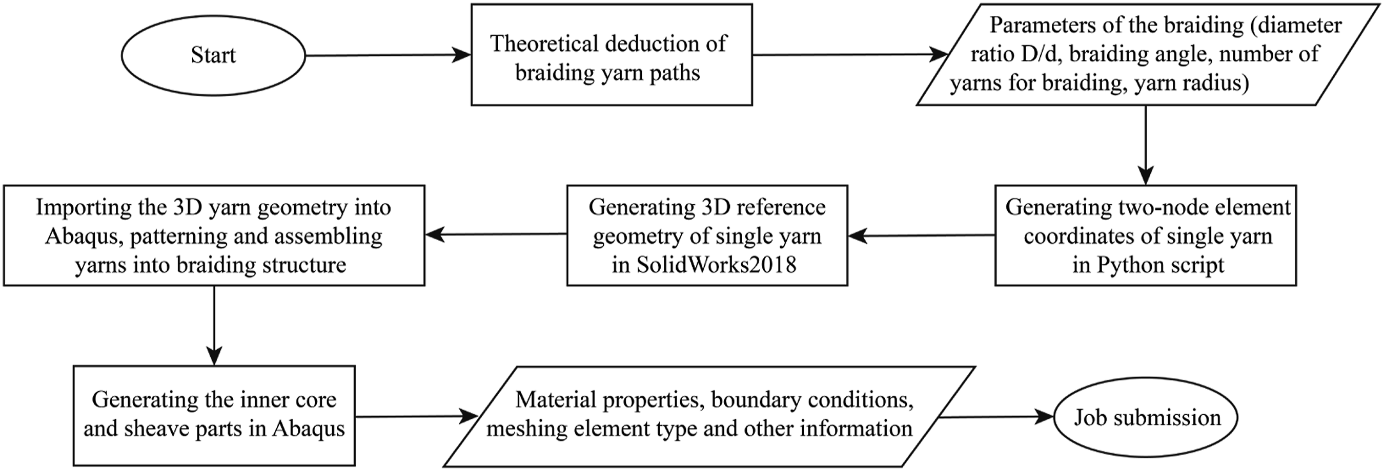
Definition of braided structure
Basic assumptions
Several interface issues are caused by the relative displacement between the internal and external yarns when the rope is bent. In bending position, the tangential displacement occurs under large normal stress and generates considerable friction forces. After frequent cycles without enough dissipation, the heat accumulates and causes a massive temperature rise which ultimately could melt the internal core yarns.17,27
Since the dynamic deformation and stress state of the external yarns carry terrific value to influence the internal yarns and the whole rope, in this study the external yarns are seen as typical braiding structures and particularly modelled as 3D elements. The internal yarns on the other hand, play a role as filling where different material could be applied and serve to prevent collapse of the external yarns when bent severely. This approach will allow to accurately track the external yarns without the need to spend huge computational resources on the internal part of the braid.
As specific use case we consider a typical modern high-end sailing rope as in Figure 2, which is a double braid, created from high-modulus polyethylene (HMPE) filaments.28,29 Such a braid uses synthetic materials such as polyethylene, polypropylene, polyester, polyamide, aramid, PBO etc.
Geometrical model
For the geometrical model we follow the approach of Tuba Alpyildiz. 6 The original yarn cross sections are considered round with a radius of r. Though in many studies the sections are assumed to be elliptical, in our case the yarns are circular but compressible within allowed compression deformation.
As the yarn helically goes up and around the central Z
0
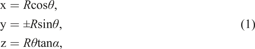
-axis, the braiding curve is firstly represented by a single helix which is wound around a cylinder of a certain radius R (Figure 4). While the braiding angle is represented as α (constant helix angle with the horizontal axes), θ is the running parameter and used to determine the radial position. The equations of such helix are then: Unfolding the braiding curve.
The two opposite directions (clockwise/counterclockwise) are represented by ±θ. As given in Figure 4, m, and n are used to count the number of yarns clockwise and counterclockwise, and β defines the difference between two yarns moving in the same direction. For one single yarn, the distance between two neighbouring encounters of the other direction is p. Keeping the Z-axis direction and unfolding the cylinder gives:


As two sets of yarns are wound helically in both the clockwise and counterclockwise direction, they are periodically interlocked at the crossing points where there is an area of overlap. When modelling, these crossing over/under are essential in the geometrical relationship, and so is the thickness (volume) of the yarns. A sine wave is introduced to define the full path of the yarns.
The yarn m
1
is shown in Figure 5 as an example, while the new X’Y’ plane is vertical to the original XZ plane in Figure 5. A basic sine wave with amplitude r and period 2p would be: The sine wave of yarn m
1
in X′ Y′ plane.

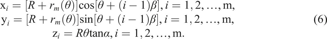
Considering aforementioned equations, the general path equation of m yarns in the XYZ coordinate depends on:

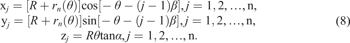
Similarly, equations of the n yarns in the other direction depend on

Finite element modelling
Geometrical yarn model
Equations (6) and (8) determined the path of braided yarns by individual parameters. Due to the mechanical feature of yarns, which mainly withstand only tension force, the yarn path is modelled as a series of two-node beam elements. The default element length of 0.6 mm is used to obtain acceptable curve smoothness. The amount and coordinates of the nodes and elements are obtained with a Python script.
However, to also take into consideration, the yarn deformation in its radius direction, as aforementioned in the mathematical model, the path is next imported into SolidWorks 2018 and a reference geometry is created as the cross section of the yarn, which is a circle with a radius of r. In sailing applications plied yarns are used consisting of two to three yarns. Considering the calculating resources that would be needed for current FEM software, the influence of plied yarns is reflected by cross-section deformation. The three-dimensional geometrical SolidWorks model with thickness is then imported into Abaqus (Figure 6) as a 3D solid part instead of the original 2D beam element. Afterwards the yarns are arrayed and assembled as a braided structure. The transformation from yarn path (top) into a 3D solid yarn with thickness (bottom).
Finite element method model
Material properties.
Model information.
The sheave is modelled as discrete rigid body because it does not move and its deformation is negligible. Two reference points are set at the ends of the inner core (on its axis). Two prescribed longitudinal displacement of 60 mm towards the sheave are assigned respectively on the reference points to create the contacting movement of the bending. The dynamic moving velocity is defined with a smooth amplitude. General friction between each two contact surfaces, including yarn-yarn friction, yarn-sheave friction, external-internal yarn friction, are assumed with a coefficient of 0.2 from the product manual.
Considering the use of Abaqus/Explicit, C3D8R elements are applied as the element type in the mesh. To acquire acceptable accuracy of the round yarn cross section deformation, 12 seeds are put on the edge as illustrated in Figure 7. The mesh of the model before bending starts, with inset detailing the 3D yarn solid elements with 12 seeds for the yarn mesh per yarn.
A mesh sensitivity study is done on the yarn meshes. Results shown in Figure 8 proves that an approximate element size of 0.3 mm is acceptable for the yarns. Mesh sensitivity study of yarns.
Results
Relative displacement
Displacement data of each node in the model could be extracted from the result. However, as the whole braiding structure engages in the bending motion, direct information of coordinate alternation is to some degree pointless. Two types of movement are observed: sliding of the yarns with respect to the interlacing point and the interlacing point moving towards the sheave due to its rotation around the internal cylinder. To identify the relative movement between different yarns, the moving of the interlacing points also needs to be considered. A set of two nodes which are placed at the same interlacing point should be selected, and respectively, they should be from two crossing yarns.
For example, in Figure 9 Node10052 on yarn 2-RAD-3 and Node10012 on yarn 1-RAD-3 are firstly observed (Figure 9) where these node and yarn codes are set by Abaqus. The exported data from Abaqus are shown in Table 3 and Table 4. Mises stress distributions after bending. Query data of Node10052 on yarn 2-RAD-3. Query data of Node10012 on yarn 1-RAD-3.


Calculated base coordinates of the interlacing point and value.

Calculated value of

Such analysis is also conducted on positions at other interlacing points. The chosen nodes, however, are mainly distributed near the maximum bending point of the rope, which is also close to the top middle part of the sheave. This is because that area is where the rope bends most and maximum deformation could happen, so it should represent the maximum displacement of yarns. We typically consider four interlacing points, and obtain an average relative displacement as

Parameter study
Geometrical parameters.
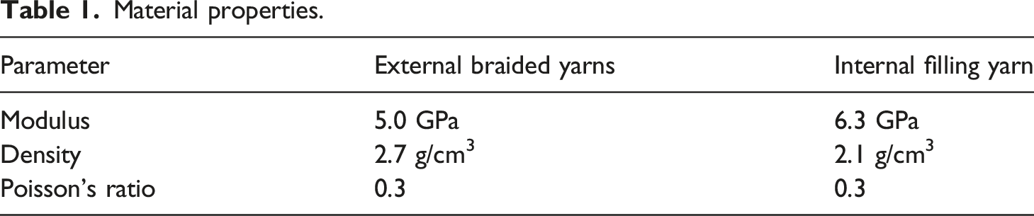
A braided rope is bent over four sheaves with different diameters in Group A, with the D/d ratio varying from 3.33 to 10. Simulated relative displacement results are presented in Figure 10(a). With the D/d ratio increasing, the relative displacement between yarns shows clear reduction for there is less bending according to the curvature of the bent rope. Stress and friction on yarns also decreases. When the D/d ratio is less than 4, the displacement at the maximum bending point can reach slightly over 0.7 mm for a braided structure with a diameter of 12 mm. Effects of (a) diameter ratio D/d, (b) braiding angle, (c) number of yarns for braiding, and (d) yarn radius on the relative displacement of the yarns after bending.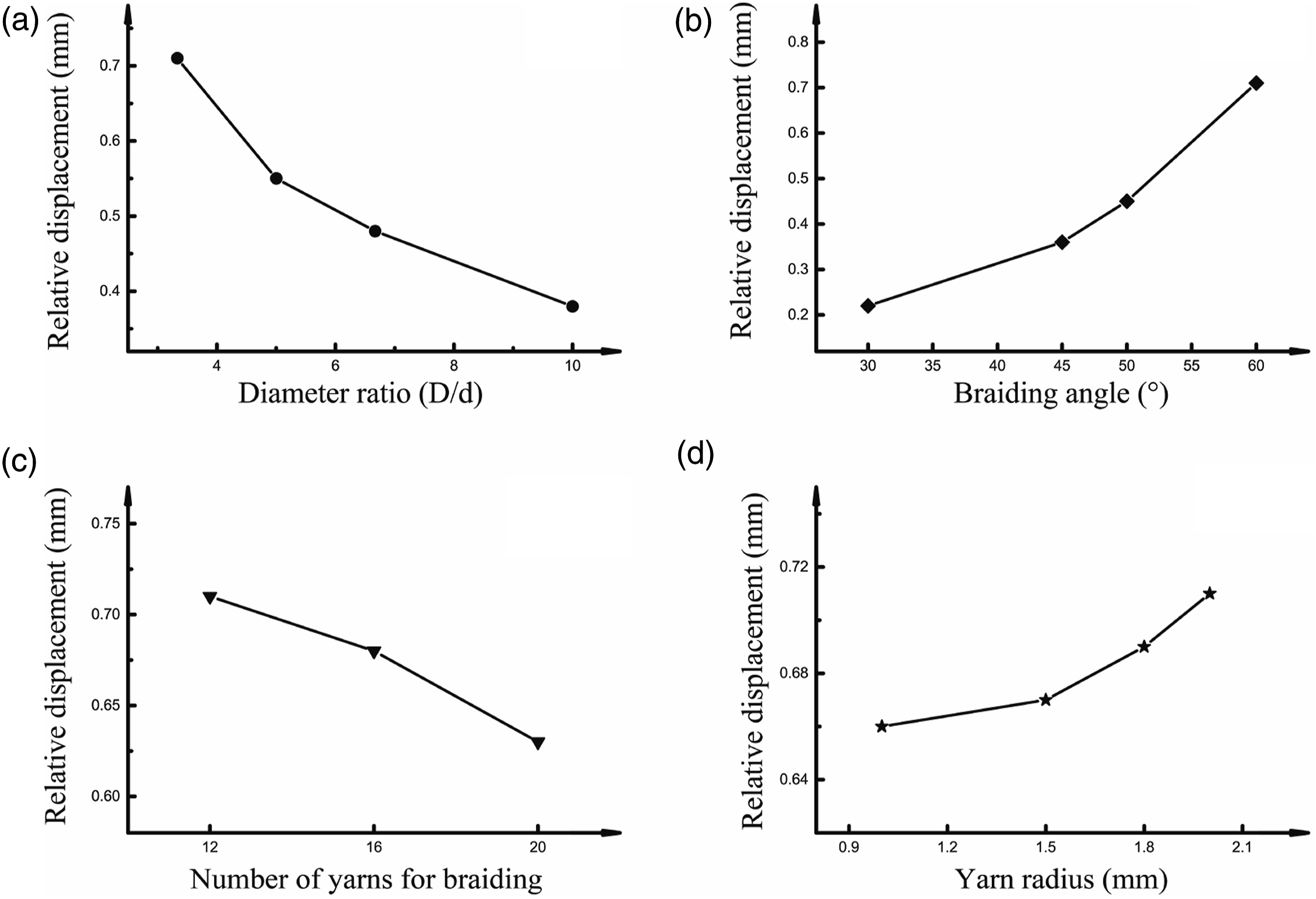
The braiding angle carries great weight in braided structure research. The relative displacement between yarns is rather small, less than 0.3 mm, when the braiding angle is 30°; the displacement grows rapidly when the braiding angle exceeds 45°. When it reaches 60°, the displacement becomes three times that of 30°. The reason for the dramatic change could be the ‘density’ difference of yarns arrayed in a certain area due to different braiding angles. Smaller braiding angle allows longer yarns winding extra circles around a cylinder of certain length and this ‘extra length’ takes part in the deformation of the whole structure when bent, so that less sliding occurs between yarns braided in opposite directions.
The result in Figure 10(c) and 10(d) demonstrates hardly any obvious connection between number of yarns for braiding and yarn radius, on the relative displacement. More yarns for braiding occupy considerable room of the structure and leaves less space for the external yarns to move and deform. The small geometrical scale of the yarn diameter determines its limitation in influencing the whole structure, compared with the diameter of the sheave and the braided rope. The slight decline of yarn displacement with thinner yarns could be due to the increasing contact area between yarns when compressed.
Contact force
As the yarns are represented as a 3D geometry in our approach, it is possible to analyse the contact forces arising, such as the yarn-yarn friction and deformation. The contour of the contact force is shown in Figure 11 for the case D/d=3.33, where 12 yarns of diameter 2 mm are braided in an angle of 60°. The node under the greatest compression appears at the area of maximum bending, where the hard contact occurs between the yarn and the sheave. Mises stress distributions after bending.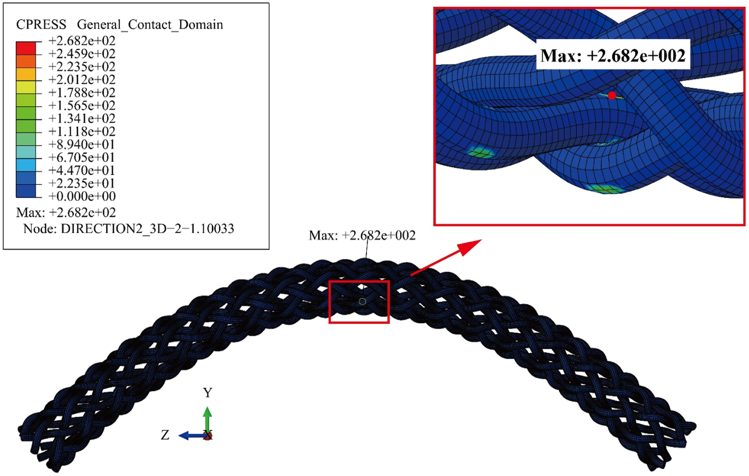
The cross section of deformed yarns in X-Y plane is as well shown in Figure 12. As aforementioned, circular sections undergo obvious deformation which become not necessarily ellipse. Particularly, different contact forces cause varying degrees of deformation. High compression forces are seen at the interlacing points between the yarns. When the braided structure is deformed due to e.g., being bent over a sheave, the interlacing nodes move, and friction caused by the normal compression force will do work. When it is a cyclic process, the heat can accumulate faster than it can dissipate, and therefore a heat problem might occur, especially inside the braided rope. Deformed yarn cross section after bending.
Discussion
The main innovation in this paper is the use of more detailed solid elements, as opposed to the standard beam elements in the global scenario, to model a yarn in the CBOS problem. This is possible as all simulations could be performed on a HPC cluster of 128 nodes (2*10-core Intel Xeon E5-2660v3, Haswell-EP @2.6 GHz). To create the solid elements, first beam elements are created, and a change to Solidworks done to convert to solid elements, before reimporting in Abaqus.
With the 3D elements, first and foremost, an accurate tracking of the interlacing points becomes possible, allowing to determine the displacement. Parametric studies can be set up with this approach. The simulation results show that two parameters most influence the displacement: D/d and braiding angle, and allow to conclude that number of yarns and yarn radius only have a minor effect. It was found that increasing D/d or decreasing the braid angle could decrease the relative displacement, while the yarn radius and number of yarns for braiding only had little influence. Smaller yarns and more yarns in the braiding structure could lead to less displacement.
Secondly, the solid element approach allows to obtain the contact forces that arise. With these two elements, displacement and contact force, future work can determine the heat generation under CBOS. A braid manufacturer can use this modelling approach to obtain the internal deformation of the yarns in the braid as the rope bends over a sheave and straightens again to the original shape, allowing optimization of the rope parameters before production.
Conclusion
This study focused on the CBOS problem which has drawn increasing attention in rope production. FEM modelling was performed with commercial software Abaqus/Explicit to simulate the bending performance over a sheave of a braided rope with a core cylinder inside, while the external yarns were modelled as 3D elements. A theoretical deduction was performed to determine the yarn paths for generating a 3D braiding rope structure through the use of several commercial software. An assessment of the relative movement between braided yarns was introduced and estimation of yarn displacement was obtained. In addition, a parametric study was carried out on factors which could influence the result.
The success of the simulation proves the feasibility of modelling and analysing the complex braided structure under specific boundary conditions. Modelling the yarns using 3D element instead of 2D beam/truss element allows to better study the yarn-level behaviour of a braid. Simulation with strong FEM software provides alternatives in predicting credible lifespan of products that cannot be easily inspected. The result, the estimation of the sliding movement, can be referred in further research or analysis on braided ropes, such as friction reduction and the heat generation problem in CBOS leading to rope degradation.
The presented simulation does have the limitation that the target nodes were placed near the maximum bending point, which could cause an overestimation of the relative moment of the yarns. Also, to create a more accurate model, modifications on both geometry and boundary condition are required such as adding sufficient pretension in a precedent step. Nevertheless, the approach here shows promising results to handle complex problems of yarn-yarn friction through FEM modelling.
Footnotes
Declaration of conflicting interests
The author(s) declared no potential conflicts of interest with respect to the research, authorship, and/or publication of this article.
Funding
The author(s) disclosed receipt of the following financial support for the research, authorship, and/or publication of this article: This study is supported by China Scholarship Council (201706710033, 201906250216) and European Commission (Erasmus+ Project ICT-Tex, 612248-EPP-1-2019-1-BG-E, Erasmus+ Project n° 2020-1-RO01-KA203-079823).