
Abstract
Finite element method can provide valuable results and information to evaluate and assess the mechanical behavior of tissue engineered scaffolds. In this investigation, a structurally and analytically based model is applied to analyze and to describe the mechanical properties of wire rope yarns as scaffold or other applications in textile engineering. In order to modeling the mechanical behavior of single yarn, non-linear hyperfoam model with three strain energy potential has been used. The results of finite element model are compared with an experimental approach and showed good agreement between software and experimental analysis with a maximum error at break of about 4.3%. As a result, validation of the finite element method is guaranteed for analysis of other structure of multi twisted yarn or wire ropes.
Introduction
Numerical methods gain a general tool to analyze loading conditions and arbitrary geometries. Among the numerical methods, finite element method (FEM) has been extensively used successfully. However, this kind of analysis needs to generate a lot of data in order to achieve properly accurate results and consumes large investment in computer resources and engineering time [1]. The exit result of FEM is an approximate solution with high accuracy that depends on the fineness of the finite element mesh and the type of element [2]. FEM has a lot of applications in different fields such as its applications to the modeling of biological systems and tissue engineering fields [3,4].
Tissue engineering is an engineering science to create functional tissues and organs for transplantation [5]. The principle of tissue engineering is that proper cells can be expanded in tissue culture and seeded into a scaffold. Scaffolds can be prepared from a specific building material with three dimensions that is similar to target tissue structurally and mechanically [6]. Because of the importance of designing scaffolds in tissue engineering close to target tissues properties, excellent research efforts have been directed to the progress of simulating and modeling approaches to design scaffolds in tissue engineering which is near the properties of target tissues. Biomaterials that can be used in biomedical applications like tissue engineering are in a wide range. Silk fibroin is one of the most attractive polymers in tissue engineering to simulate an anisotropic and viscoelastic mechanical behavior [7]. Silk fibroin is a fibrous protein that can provide a highly matched set of material options as biomaterial for fabrication of scaffolds because of the magnificent mechanical properties, biocompatibility, and biodegradability [8].
Recently, theoretical modellings have considerable potential to progress existing protocols [9]. Lemon et al. have reported a mathematical model for the differentiation and proliferation of human mesenchymal stem cells grown inside artificial porous scaffolds under different oxygen concentrations [10]. The accumulation of collagen and glycosaminoglycan and the degradation of a polymer-based scaffold in an engineered cartilage were developed with mathematical models by Christopher et al. [11]. Also, FEM was performed to simulate the mechanical response of the engineered leaflets to a transvalvular aortic pressure load after two, three, and four weeks of culturing [12]. Silk fibroin wire rope yarn in five level by changing number of yarn and number of twist in each level was investigated as a scaffold in ligament tissue engineering by Altman et al. to reduce linear stiffness. Also, Costello’s equation for a three-strand wire rope was used to predict its mechanical properties [13].
In our previous work, intelligent neural network and genetic algorithm methods were used for prediction of mechanical behavior of silk wire rope scaffold for final application in tendon and ligament tissue engineering [14,15]. In the following, using FEM with computer design can be a powerful tool to model and to analyze wire strands and ropes or multiple twisted yarn in different applications like tissue engineering for the first time. There are three fundamental steps to identify advanced models and to analyze wire strands and ropes. These steps include designing the geometric model, generating the engineering model using computer tools, and applying the FEM to analyze under the required loading [16].
So, finite element model is a useful and well-known tool for investigating the mechanical properties of wire rope structures that has already been applied, as reported by several authors like Stanova et al. [17], Erdönmez and Imark [18,19]. In this paper, finite element technique is used in order to achieve a higher level of verification and to model experimental effort in tendon and ligament tissue engineering by designing silk wire rope scaffold. This kind of model can be generalized for multiple twisted yarns in different fields of textile engineering. An experimental study is also done for comparison.
Materials and methods
Materials
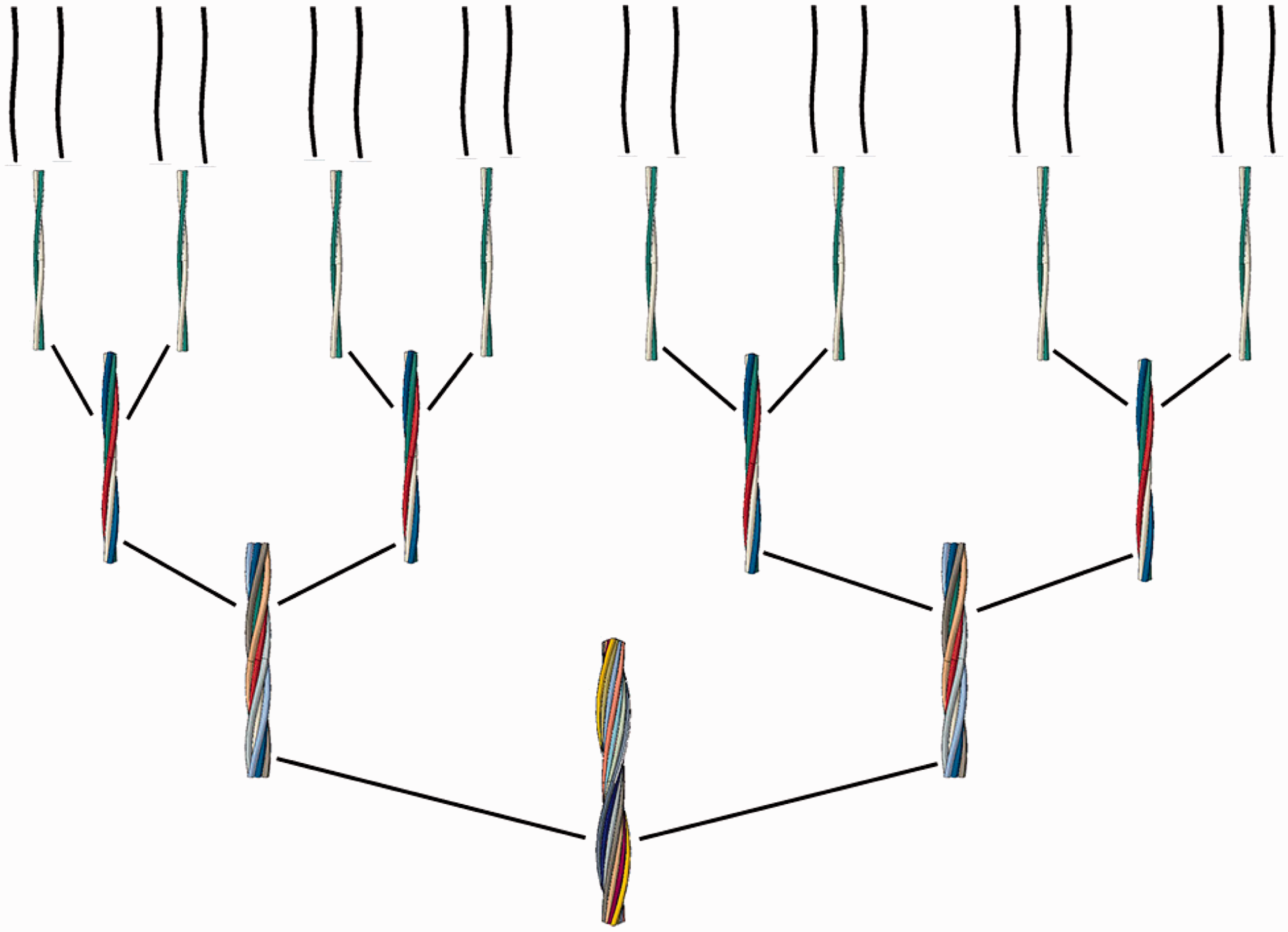
Degummed silk fibroin as a biomaterial was prepared after degumming process. Sericin layer was removed by degumming process using 0.25% Na2CO3 for 30 min at 95℃. Then four level wire rope was fabricated which comprised of 2, 2, 2, 2 yarn in first to fourth layer with 20 twist per meter for each layer. This structure is the simplest type to design silk wire rope with the least number of yarns in each layer. Twisted silk wire rope scaffolds were designed with a hierarchical structure like the arrangement of fibers in some tissues like collagen fibers in ligament and tendon tissues. In Figure 1 the twister machine and in Figure 2 the wire rope scaffold hierarchy are schematically depicted.
Schematic of the simple twister machine to fabricate silk wire rope scaffold. Schematic of a hierarchal organization of twisted silk wire rope scaffold.
Finite element implementation
Finite element modeling
Samples of wire rope yarn including 2, 4, 8, and 16 yarn twisted strand were modeled by CATIA program software. Silk yarn cross section was assumed as circle with 0.3 mm diameter and 25 mm length that has a twist in the middle of yarns. Diameter of silk yarn was calculated according to Tex count of yarn. Table 1 shows the properties of single silk yarn. Figures 3 and 4 show a wire rope scaffold with two strands in first layer and the cross sections of twisted wire rope with 2, 4, 8, and 16 strands in first to fourth layers, respectively.
Wire rope yarn with two strands. Wire rope cross section with (a) two, (b) four, (c) eight, and (d) 16 strands. Properties of single silk yarn.


Mechanical behavior of single silk yarn
Stress–strain curve and related values of single silk yarn as well as 2, 4, 8, and 16 yarn strand were drawn and measured by Zwick mechanical testing machine. Test length was set 25 mm which is similar to native tendon and ligament tissues length by 50 mm/min cross head speed.
For modeling mechanical behavior of single yarn ABAQUS software was used. A material model normally used to describe a silk yarn was non-linear hyperfoam model described by the Ogden strain energy formulation, equation (1) [20,21],

Where U is strain energy function, N is a polynomial order and 
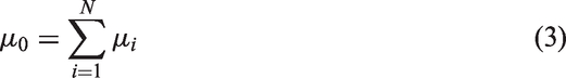
The coefficients μi are related to the initial shear modulus, μ0, by the expression shown in the following equation,
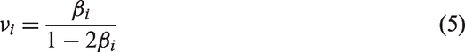
For each time in the energy function, the coefficient βi determines the degree of compressibility. βi, is related to Poisson’s ratio, νi, by the expression shown in equations (4) and (5)

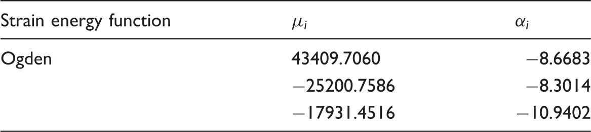
The coefficients used in the hyperfoam model within ABAQUS can be defined directly, or alternatively; actual test data can be specified (which is then used by ABAQUS to calculate the coefficients). Therefore, the uniaxial test data of stress–strain curve were used to predict mechanical behavior of single silk yarn with three-strain energy potential. Figure 5 shows uniaxial stress–strain curve test of single silk yarn. Thirty samples were prepared for tensile test using Zwick machine according to ASTM C1557. Table 2 shows the parameters of non-linear Ogden hyperfoam strain energy function of silk yarn.
Stress–strain curve of single silk yarn. Parameters of non-linear Ogden hyperfoam strain energy function for silk yarn.
Single silk yarn has been made by many monofilaments gathered by staple yarn spinning. This method of spinning makes a lot of porosity in yarn. Therefore the assumed mechanical behavior of silk yarn is similar to hyperfoam materials.
Contact
Hanging fiber test was used to calculate friction coefficient between fibers [22]. Two cut yarns were necessary for the test. One end of the first silk yarn was fixed on axial tension machine vertically and another end was drawn on to the sinker. The length of this yarn was set as 20 cm. Second yarn was adjoined to a frame with ⨿ shape horizontally. Effective length of second yarn was 5 cm. Figure 6 shows a schematic of hanging fiber test method.
Front and side view of hanging fiber test method.
In Figure 6, D and L distances were set as 15 cm and 6.1 cm, respectively. Therefore ϕ equals to 22.1°. At the beginning of the test, displacement of upper clamp was 5 mm/min velocity up and down. Because ϕ was constant during the test low clamp displacement has been chosen (5 mm). Therefore, difference in ϕ was 1.3±0.3. When the upper clamp moves up, the normal force is RU and when it moves down, the normal force is RD. So R, RU as well as RD can be calculated as follow:


Where R is the average of normal force, FU is friction force in move up, and FD is friction force in move down. If F would be the average of friction force in moving up and down, therefore:

P is a new parameter that is calculated using equation (10),

Finally, friction coefficient can be calculated by equation (11):

In this experiment, friction coefficient between silk yarns was calculated as 0.04. Hanging fiber test has been done by Zwick 1446-60 mechanical testing machine. To model contact between yarns, general contact (Explicit) was used in finite element software.
Boundary condition
All numerical analyses of strand behavior under axial tension loads were performed with one end clamp (displacement in x, y, and z directions were disabled) and second free end submitted to a tension load (displacement in z direction).
Finite element mesh generation
C3D8R element types in ABAQUS/Explicit element library with reduced integration and hourglass control, which is an eight-node linear brick were applied for the structural discretization. Figure 7 shows mesh generation of single yarn.
Mesh generation of single silk yarn.
Results and discussion
Figure 8 shows Von Mises stress result of finite element analysis on single silk yarn. Von Mises stress can be calculated by equation (12). Generally, Von Mises stress is a criterion to show strength and stress concentration on different points of yarn. According to Figure 9, hyperfoam mechanical behavior of single silk yarn has an acceptable conformity with stress–strain curve of single yarn. It means, obtained results from the experimental measurement indicate fairly good agreement between the obtained results from the simulation.
Von Mises stress (MPa) results of finite element analysis on single yarn. Stress–strain curves of experimental and finite element results for single yarn.


In the same way, finite element analyses have been done for other models (2, 4, 8, and 16 strand yarns). Contact and coefficient of friction between yarns are important to modeling and explicit method was also used. Figure 10 shows finite element analysis of 2, 4, 8, and 16 strand yarns under axial tension load.
Von Mises stress (MPa) results of finite element analysis for samples: (a) two yarns; (b) four yarns; (c) eight yarns; (d) 16 yarns.
Comparison between finite element and experimental results of 2, 4, 8, and 16 silk wire rope is shown by force versus displacement curves in Figure 11.
Axial force versus displacement curves of experimental and FE results.
Experimental and FEM force at break of 2, 4, 8, and 16 silk wire rope yarns.

Undoubtedly, this kind of model should be further improved to become a useful tool for the engineering of twisted yarn. On the other hand, this model can be generalized to predict mechanical properties of multi twisted structures by changing the number of single yarn. For example, mechanical properties of designed scaffolds in tendon and ligament tissue engineering are so vital that should be close to target tissues. By modeling and simulating, it is possible to predict final properties which are closer to the experimental results. So the presented model is a promising method to design and fabricate multi twisted and wire rope structures for different applications.
Conclusion
A finite element model of the wire rope was developed to predict mechanical properties of strands. As a matter of fact, a comparative study of analytical software and experimental methods for computation of the mechanical behavior of the wire rope or multi twisted yarns was presented. The non-linear hyperfoam model has been used for single silk yarn in the finite element software. The non-linear hyperfoam model with three strain energy potential has a good agreement between experimental and simulation results for textile materials like silk yarn. Also, the predicted mechanical values agree well with the result of the validation experiment for different number of strands with maximum error of 4.3%.
Footnotes
Declaration of Conflicting Interests
The author(s) declared no potential conflicts of interest with respect to the research, authorship, and/or publication of this article.
Funding
The author(s) received no financial support for the research, authorship, and/or publication of this article.