
Abstract
Lightweight armor with excellent protection against ballistic impacts are pursued by researchers worldwide. This paper systematically investigates the effect of the Z-binding depths on the ballistic performance and failure mechanisms of para-aramid 3D fabrics. Two types of 3D woven through-the-thickness angle-interlock fabrics were designed and fabricated in comparison to the 2D plain weave fabric. The ballistic tests and finite element simulation analyses were carried out based on a similar areal density of 5.2 kg/m2 by layering up the fabrics. According to the experimental results, the variability and cumulative probability of penetration of the 20-P are higher than that of the 3D fabric systems, resulting in a 2.5% higher ballistic limit V50 of 8-5 TA than 20-P. Fabric plies failed abruptly in the 2D system, while the 3D system showed a progressive failure mode. The Z-warps, configure through the thickness of the fabric, result in the projectile tumbling and deviating from its original direction. A larger binding depth can help to prolong the defending process, which will mobilize more yarns to resist the projectile impact. The back-face deformation is well constrained by the 3D fabrics. Due to the fact that the designed 3D woven fabrics are more moldable than the plain weave, it could be potential candidates for the engineering design of female bullet-proof vest interlining.
Keywords
Introduction
Engineering design of fabrics with lighter weight and better protection is required for the development of future personal protective equipment. Unidirectional cloth (UD) and 2D woven fabrics made from high-performance fibers are often used to manufacture soft ballistic armor. The use of innovative fiber and resin materials and designing novel structures for improved utilization of the materials are both popular stratergies for engineering lightweight body armor. Many factors affect the ballistic performance of a fabric system, including the layup design,1,2 projectile impact velocity, 3 cumulative damage, 4 boundary conditions 5 and so on. Chen et al. 1 mentioned that shear failure precedes tensile failure during ballistic impact on multilayer woven fabrics, which prevents high-strength fibers from reaching their full energy absorption potential, suggesting a shear-resistant material at the impact-face and a stretch-resistant material at the back-face. Min et al. 2 investigated the mechanisms of angle-plied systems. The angle-laid system with fabric plies oriented by designed offset angles will be more energy absorbing than the align-laid systems until the impact velocity reaches a critical value. Zhu et al. 3 found the ballistic performance of fabric reinforced composites to be highly dependent on the impact velocity. With the increase in impact velocity, the energy absorption capacity of the composites is enhanced, and the yarn breakage and resin plasticization become more obvious. Zhou et al. 4 studied the effect of cumulative damage on the energy absorption capacity of plain weave fabric system, and found that the pre-damaged systems appear to be less protective than the undamaged systems in most cases.
However, when using UD and 2D fabrics for complex 3D shapes, the resulting stitching, folding and overlapping can lead to breaks or gaps in the yarns, which can negatively affect ballistic performance. The multiply 3D woven fabric systems exhibit potentials in ballistic resistance by having Z-binding yarns and layered structures. Multiple layers of wadding warp and weft yarns are bound together by the Z-warps. The Z-binding depth refers to the number of weft yarn layers interlaced along the through-the-thickness direction of the fabrics. Moreover, 3D woven fabrics are increasingly used in complex hyperbolic structures due to their excellent formability.6–8 Under the same areal density, the aramid composite panel with a larger ply areal density and fewer reinforcement plies would result in less damage. 9 The areal density of the 3D fabrics Is often greater than that of the 2D fabrics, resulting in fewer number of laminate plies required for reaching a designed weight.
Many researchers devoted to the design of 3D fabrics for enhanced mechanical properties. Nayak et al. 10 fabricated 3D E-glass fabric reinforced epoxy composites and conducted tensile, flexural, and interlaminar shear stress tests, and found that shear stress induced at the interface of each lamina was seen as the major reason for the drop in strength. Liu et al. 11 fabricated four types of 3D fabrics for quasi-static three-point bending tests and found that the angle-interlock woven structures have a larger flexural strength (50%), modulus (40%), and failure resistance than the orthogonal-woven structures. Wu et al. 5 investigated on the influence of warp yarn patterns on the ballistic performance of 3D through-the-thickness orthogonal woven fabrics under different clamping conditions, which indicated that the structure had limited influence on the ballistic performance and the fabric with higher flexibility was more sensitive to the boundary conditions. Interestingly, Han et al. 12 introduced polycarbonate in the aramid fabric reinforced composites, and found that neat fabrics exhibited optimal ballistic performance, with the main damage mechanism being yarns tensile breakage.
It is revealed that the weft yarns contribute more than the warp yarns in a 3D fabric in resisting ballistic impacts.8,13 Ma et al. 14 designed a novel 3D fabric with weft yarns crimped to a similar extent as the warp yarns, and the structure exhibited improved ballistic performance. Wei et al. 8 study the impact mechanism of 3DAWF under ballistic penetration, the results show that the stressed area along the weft direction is twice the size along warp direction. Wang et al. 15 study the mechanical behavior and the complicated failure mechanism of a novel aluminium matrix composites reinforced by 3D orthogonal woven carbon fabric, the results indicate that the increase of warp or weft density could improve the tensile strength and elastic modulus, but the tensile elongation decreases with the increase of weft density. Neale et al. 16 found that subtle changes in weft density could significantly affect the energy absorption in the warp direction, while the binding Z-warps play a vital role in the bulletproof performance.
Z-binders provides an extra mechanism for energy absorption during the projectile penetration process. Zhang et al. 17 investigated on effects of spacer yarns in a 3D spacer fabric made of 300D/96F polyester multifilaments, and found that the compression resistance in the densification stage of the fabric increases with increasing the number of spacer monofilaments adopted due to the interactions between the spacer yarns. Guo et al. 18 designed a multi-axis 3D angle-interlock woven carbon fabric reinforced composite. The insertion of bias yarns which connect mutiply layers improved the in-plane shear modulus and strength significantly. Li et al. 19 studied the effect of seaming on the ballistic performance of para-aramid fabrics, and found that the seamed systems exhibit better ballistic performance than multi-layer fabrics without linkages. Zhou et al. 20 used conventional cotton sewing threads to stitch the fabric, and found a 146% improvement in energy absorption capacity when compared with the unstitched samples. However, reports regarding the failure mechanisms and influences of the Z-binding depth on the ballistic performance of fabrics are rarely seen.
Hoping to provide guidance on the future design of soft armors with improved protection, the aim of this paper is to systematically study the effect of Z-warp binding depths on the ballistic performance and failure mechanisms of 3D through-the-thickness angle-interlock fabrics in a multiply system. 3D woven fabrics with different Z-warp binding depths are designed and layered-up. Their ballistic limit is evaluated by non-perforation ballistic tests and compared to the 2D plain weave structures experimentally. Finite element models are constructed to understand the failure mechanisms in terms of their energy absorption, ply failure times, projectile resistance and stress distribution.
Methodology
Design of the 3D woven through-the-thickness angle-interlock fabric systems
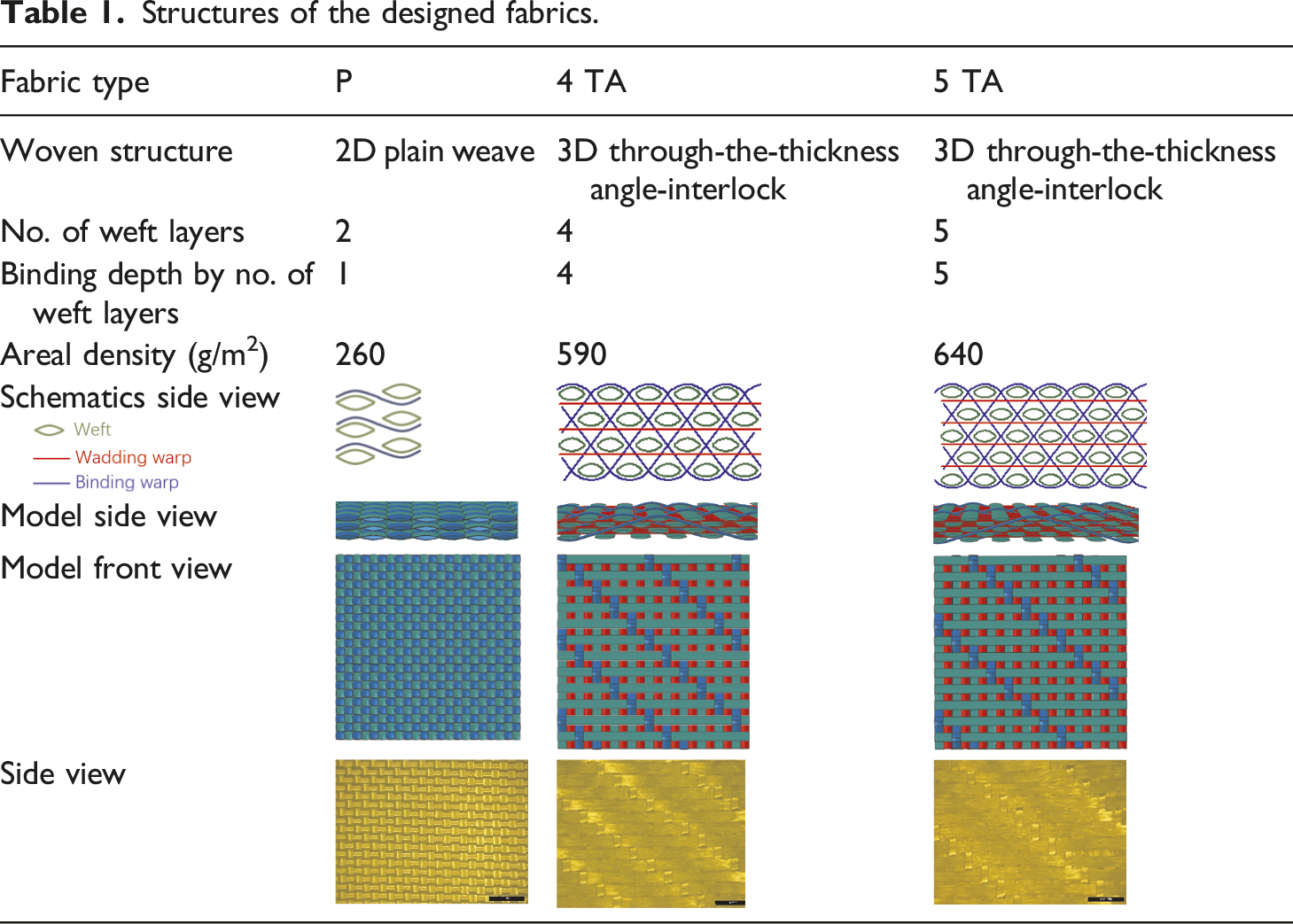
Structures of the designed fabrics.
Structural parameters of the laminated systems for ballistic tests.
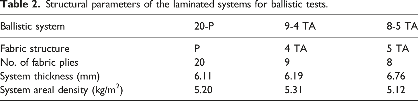
The fabrics were stacked into systems to reach an equivalent areal density (≈5.2 kg/m2) and thickness (≈6 mm) for ballistic performance evaluations. The fabric lay-up sequence follows a [0/90]n ply orientation. The compositions of ballistic systems are listed in Table 2.
Experimental investigation on the ballistic performance
Following the standard GA/T 950–2019 V50 test methods for ballistic materials and products, the ballistic limits V50 of the designed fabric systems were tested on a ballistic range shown in Figure 1. Ballistic impact test: (a) Testing set-up (b) 1.1 g projectile.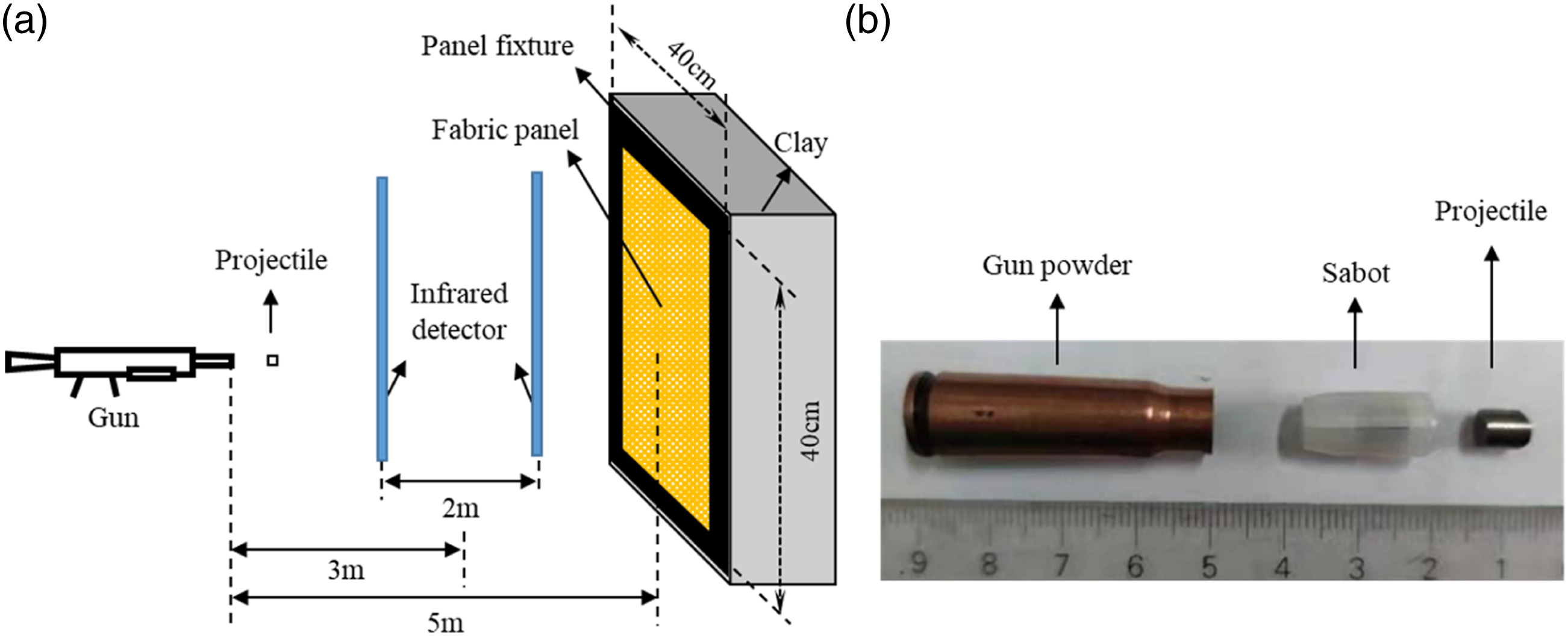
The ballistic performance of designed fabric systems.

The V50 is the ballistic limit at which the projectile stands a 50% chance of penetrating the system. It is calculated based on the average impact velocity of six fair shots, as indicated in equation (1). The six shots are the three lowest impact velocities resulting in penetration and the three highest impact velocities resulting in non-perforation, respectively.
As listed in Table 3, the 3D woven system 8-5 TA shows the highest ballistic limit V50, which is 2.5% higher than that of the 2D plain weave 20-P (the lowest V50). To normalize the differences in areal density, specific energy absorption (SEA50) is calculated following equation (2).
The SEA50s of the 3D systems are slightly higher, with that of the 8-5 TA 6.7% higher than the 2D system 20-P. This is consistent with the findings from Abtew et al. 6 and Muñoz R et al., 21 which also mentioned that the presence of z-yarns did not significantly improve the ballistic performance compared with 2D wovens.
The impact behavior of textiles is essentially probabilistic, which can be expressed by a continuous probabilistic velocity response (PVR) curve. The cumulative distribution function (CDF), also known as the distribution function, is the integral of the probability density function and can fully describe the probability distribution of a random variable X. It has been found to represent the PVR of materials well.
22
In impact tests, the impact velocity of some non-penetrating shots is higher than that of some penetrating shots due to the probabilistic nature of the impact behavior. The region between the minimum penetration velocity and the maximum non-penetration velocity is known as the zone of mixed results (ZMR). Both the PVR curve and the width of the ZMR can be used to characterize the degree of variability in ballistic limits. The PVR and ZMR of the designed fabric systems are illustrated in Figure 2. Sample ballistic data and comparison of ZMR and PVR curve.
The ZMRs of the 3D fabrics are narrower than that of the plain weave structure, which indicates stabler ballistic resistance of the 3D structures. Meanwhile, the PVR of the plain weave system locates above the 3D systems. The probability of penetration for the plain weave system is higher than that of 3D ones. The 3D 8-5 TA exhibits a better ballistic performance than 9-4 TA when the impact velocity is higher than 544.83 m/s, which can be considered as the critical impact velocity for the two types of 3D strutures.
FE model establishment
Model description
Finite element (FE) models were established to simulate the ballistic responses of fabric systems with different binding depths. To control the computation time, the size of each fabric ply was set to 20 × 20 mm and stacked following the specifications in Table 2. All of the parts in these models meshed with 8-node solid elements (C3D8R). Three fabric models were established, and only 9-4 TA was listed in Figure 3(c). The yarns are with lenticular cross-sections and assembled to form the fabric, as shown in Figure 3. Model size and mesh division: (a) Binding warp yarn; (b) Projectile; (c) Assembly model of 9-4 TA; (d) Weft yarn.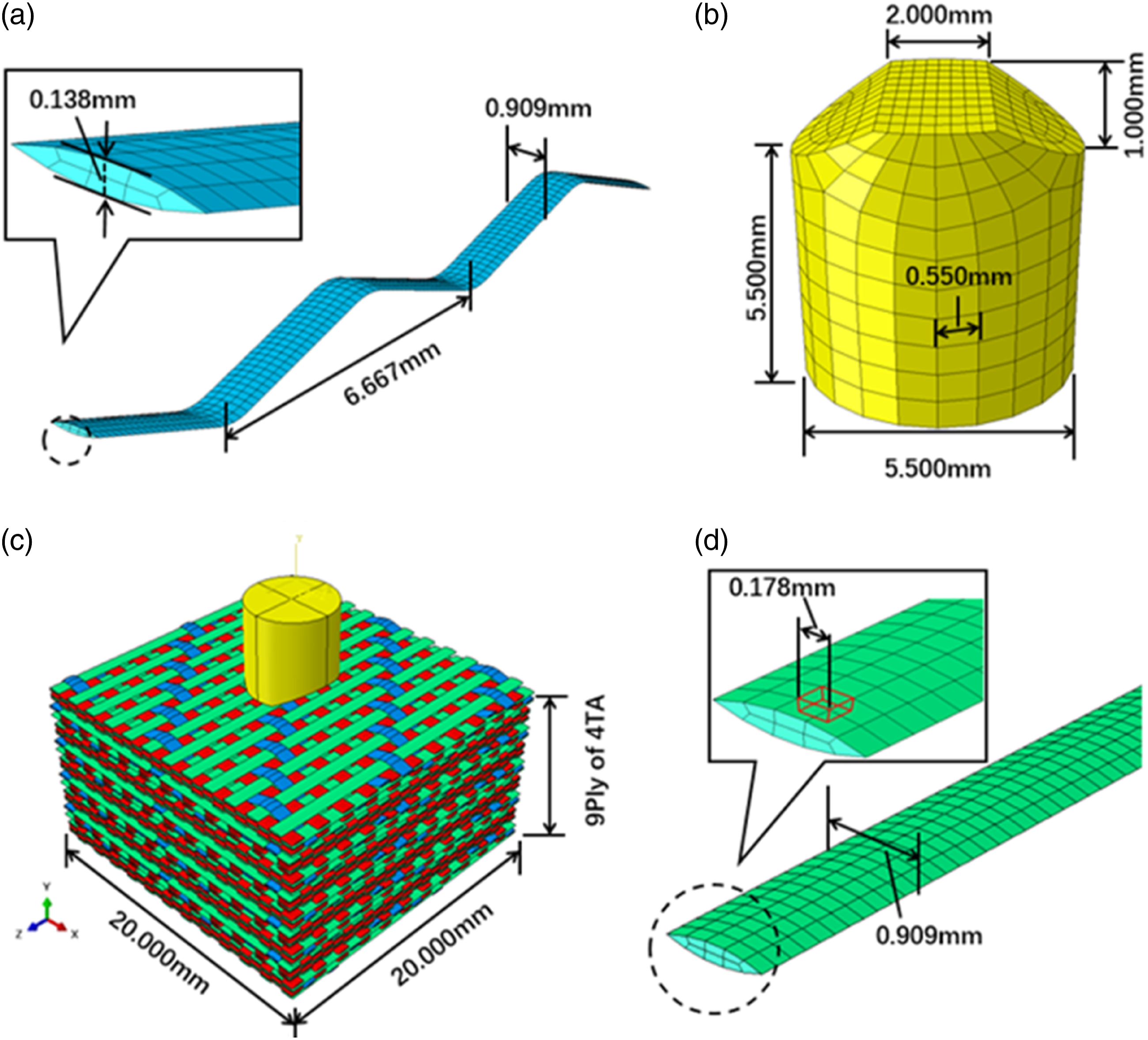
The models simulate the non-perforation ballistic tests aforementioned. The projectile hits the center of the fabrics perpendicularly with a rigid body constraint. A global frictional coefficient 0.15 is employed. 23 To simulate the actual clamping schemes in the ballistic experiments, a fixed boundary condition is applied on the four sides of the fabric system. The initial position of the projectile is right above the center of the fabric, with a predefine field of 515 m/s impact velocity along the through-thickness direction of the fabrics.
Material properties. 24

Model validation
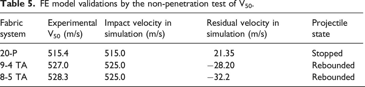
FE model validations by the non-penetration test of V50.
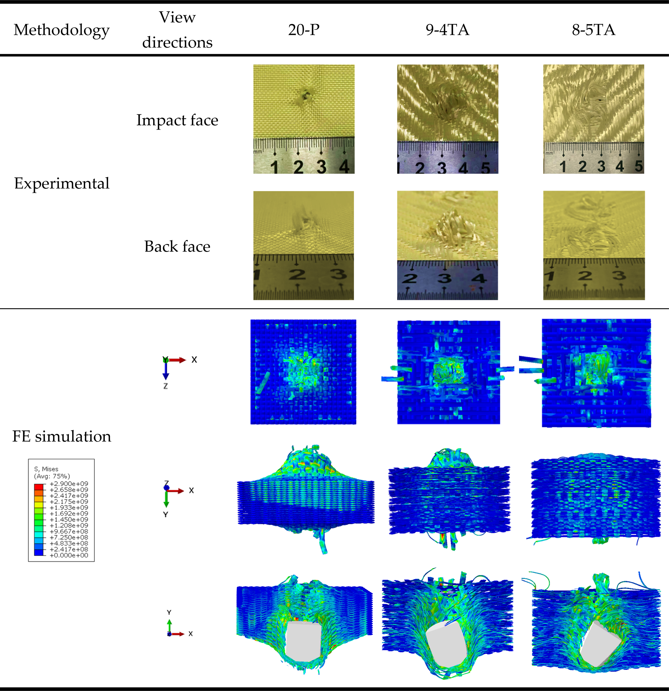
Post-mortems of the multiply fabric system.

According to Table 5, the residual velocities demonstrate an approximate ±30 m/s difference to the experiments in all cases. The differences can be corresponded to a 0.5 J energy, accounting for 0.3% of the total impact energy. The rebounded projectile indicates better ballistic resistance. The projectile will eventually stop given enough computing time, and the residual velocities are angular due to the projectile tumbling. It is also found that the results agree with that of the ballistic tests by having the projectiles tumbled in the systems at their critical states.
The deformation morphology listed in Table 6 demonstrated good agreement between the experimental and numerical results on both sides of the systems. Fabric windowing on the impact face and indentation on the back face is witnessed in all cases. All deformations are well-contained in a dimension of 20 × 20 mm, which is the size of the model.
Numerical analyses of the ballistic responses
The ballistic performance and failure mechanisms of the designed fabric systems at the impact velocity of 515 m/s are compared in terms of their energy absorption, ply failure time, stress distribution and deformation, respectively.
Energy absorption
The major energy dissipation modes in the projectile penetration process are kinetic energy (KE), internal energy (IE) and frictional dissipative energy (FD) and others, as shown in equation (3). The internal energy IE consists of two parts, namely the recoverable strain energy and plastic deformation energy.
The impact energy carried by the projectile is 145.87 J in all cases. As can be seen from Figure 4, the energy absorption of each system is at an equivalent level of 140 J, with a 1.92% maximum difference occurring between 20-P and 8-5 TA systems. The proportions of FD in plain weave and 3D systems are almost identical. The 20-P mainly converts the projectile impact energy into IE, which can be related to yarn fracture by tensile and shear failures. The results are consistent with the findings of Bai et al.,
28
which mentioned that more of the projectile impact energy is converted into IE of the fabrics with the increase of impact energy. The 3D systems possess lower IE ratios, indicating fewer yarn fractures. The relative proportion of KE in 3D fabric is significantly higher than that of the plain, which means the presence of binding yarn can help to evoke more secondary yarns to participate in impact energy absorption. Other than that, the mobility of yarns can be restricted. Total energy absorption distribution of FE models.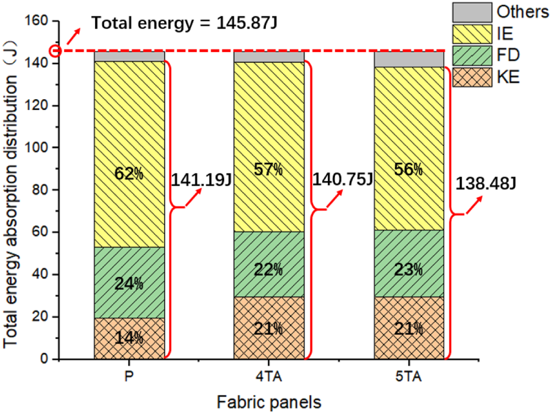
Ply failure time
In order to compare the ballistic responses of each structure, the failure time and sequences of each ply within a multiply system are presented in Figure 5. Each fabric ply is accounted as failed once perforated by the projectile with its corresponding primary yarns fail. The results were examined at 5 μs intervals. Yarn failure time by plies: (a) 20-P; (b) 9-4 TA; (c) 8-5 TA.
Two distinguished ply failure patterns can be noticed in 2D and 3D systems. For the 2D plain weave system 20-P the fabric plies failed in groups. A premature fracture of the yarns near the impact face, resulted in two-thirds of the fabric plies failing simultaneously between 10 μs and 20 μs. Whereas the 3D structures demonstrated a progressive failure mode by having the fabric plies within a system fail one after another. The resisting time of the 3D systems are longer. The prolonged overall failure time offers better chances to dissipate the impact stress.
It is also noticed that the V50 of 20-P evaluated by the non-penetration ballistic tests is close to the impact velocity employed in the FE simulation, which is 515 m/s. It is found from the ballistic test result that, 19 of 20 plies have been penetrated, and the last ply also reached a critical state. A good agreement between the FE and experimental results is noticed.
The presence of Z yarn in 3D fabrics connects the yarns in the fabric ply, each of which tends to be resistant to projectile penetration independently. The 2D plain system lacks of binding provided by the Z-warps. Each ply resists the projectile independently, in a stratified way. Taking the point of 20 μs as a reference, where 2/3 of the fabric plies failed in 20-P. Only the first plies of the 3D systems failed by that time. Even though the front plies within the 2D plain weave system failed earlier, the rear plies are speculated to have a stronger resistance to the proceeding projectile by absorbing 1.92% more energy (IE + KE + FD) than 8-5 TA. This indicates that a hybrid multiply system with 3D fabrics as front plies and 2D plain weave fabrics as rear plies could be a lightweight solution for the future soft armor design.
Projectile deflection
Measurement of projectile deflection angle.


Impact resistance
The time history of the residual projectile velocity is shown in Figure 6. The cross-sectional views are plotted besides the icons to illustrate the status of the projectile at the end of the impact. The time durations were set to ensure the completion of all impact processes accordingly. The velocity of a projectile of 20-P experiences a sudden drop during 0–20 μs and becomes stabilized gradually. 8-5 TA shows a slowest velocity drop, which means it has a longer resisting time to enable the dispersal of stress during impact. The trend of 9-4 TA is similar to that of the 8-5 TA, only slightly steeper. The velocity of the projectile in the fabric system does not drop to zero because it deviats from the vertical direction and tumbles in the system. Time history of the velocity from FE models.
Figure 7 shows the time history of projectile acceleration. Similar to the failure time, the acceleration of the plain weave system 20-P is different from that of the 3D systems. The time history of 20-P acceleration is divided into three stages. The first stage is 0–10 μs, where the reaction force on the projectile increases sharply and reaches a peak acceleration of 28 × 106 m/s2. The second stage is 10–35 μs, the acceleration shows a decreasing trend, indicating primary yarn failure during the process. The third stage is 35–100 μs, where the curve flattens out, and the projectile stops within the system eventually. These three stages correspond well to the weft yarn failure time summarized in Figure 5. Projectile acceleration over time.
The peak acceleration of 20-P is about twice that of 3D fabrics. A larger acceleration corresponds to a greater reaction force, which is more likely to cause damage to the body behind the fabric systems. Although 20-P exhibits stronger resistance at the initial stage of impact it is inadequate to resist subsequent penetration. In addition, there is only one acceleration peak occurs in 20-P. While the 3D fabric systems showed multiple peaks, suggesting that their resistance to projectile penetration is performed in several stages. There are two distinct peaks for 9-4 TA and three peaks for 8-5 TA. The appearance of the corresponding peak in 8-5 TA lags behind that of 9-4 TA. It means the impact energy is dispersed and absorbed in a relatively progressive manner for 8-5 TA. This phenomenon matches what is speculated in Section 3.2. Therefore, the 3D fabric system may offer better protection over the body from the impact.
Stress distribution
To characterize the transverse deformation of each structure, the BFS (Back-face signature) of the last fabric ply along the through-the-thickness direction is plotted in Figure 8. The largest BFS is observed at 20-P (5.97 mm), followed by 9-4 TA (5.83 mm) and 8-5 TA (3.34 mm). The 20-P is found prone to stress concentration, which leads to a deeper BFS. The BFS of 8-5 TA is 44.1% smaller than that of 20-P. In addition, the bake-face damage of system 20-P is particularly significant, the system has almost been completely penetrated, followed by 9-4 TA. While the 8-5 TA stopped the projectile at an impact speed of 515 m/s and the transverse deflection of 8-5 TA is the smallest. Accroding to Guo et al.,
18
the specimen with a larger proportion of bias yarn produce greater resistance under the in-plane loads, and experiences larger displacement before achieving the maximum load. Gu
29
also mentioned that the structural stability of the 3D fabric depends on the Z-yarns, as they constrain the warp and weft yarn from slipping and the breakage of Z-yarns will induce the structure to collapse. It can be inferred that 3D fabric systems with a deeper Z-binding depth are better at constraining the back-face deformation well by limiting the displacement of warp and weft yarns within a fabric ply along the through-the-thickness direction during the course of a ballistic impact. BFS of fabric systems: (a) 20-P; (b) 9-4 TA; (c) 8-5 TA.
The back-face stress distributions of each system are shown in Figure 9. Supporting the findings witnessed in Figure 8, the deformation range of 20-P is the smallest, indicating an obvious stress concentration near the impact location. It can lead to premature breakage of the primary yarns in 20-P. The back-face stressed range of 8-5 TA is 56.2% wider than that of the 20-P, suggesting a more uniform stress distribution across plies and better structural stability has been provided by a deeper binding depth. Stress distribution of different fabric systems: (a) 20-P; (b) 9-4 TA; (c) 8-5 TA.
To investigate the through-the-thickness stress propagation, a node at a depth of 6 mm in the center of the system is selected in reference to the thickness of 20-P. The Von Mises stress at the reference node over time is plotted in Figure 10. Mises stress over time of system body-center position.
In terms of impact response time, the 20-P responds right after the impact occurs, followed by 9-4 TA with 5 μs later and 8-5 TA with 10 μs later. The delayed responses indicate that the deeper the binding depth is, the better the stress transfer time can be prolonged by the front ply, which is consistent with the findings summarized in Section 3.2, associated with the projectile acceleration and the ply failure time. Also, wider stress distribution can be witnessed in 8-5 TA when compared to the other two structures. The peak stress experienced by the reference node in 8-5 TA is 25% lower in general, suggesting an improved deactivation effect by the 3D fabrics with larger Z-warp binding depths.
It is speculated that a hybrid multiply system with the 3D fabrics as the rear plies and plain weave as the front plies could be a lightweight solution for the future soft armor design. As it can provide the system with an abrupt resistance at the initial stage and help to constrain the back-face deformation progressively. Limited by the heald frame capacity of our loom, the maximum number of weft layers that can be achieved in a through-the-thickness angle-interlock fabric is five. Further studies on the hybrid lay-up design of the system, as well as the influences by greater Z-binding depths of the fabrics are both worth investigating topics.
Conclusions
This paper aims to systematically examine the effect of Z-binding depth on the ballistic performance and failure mechanisms of the 3D through-the-thickness angle-interlock para-aramid fabrics. A yarn-level finite element model is developed and verified against the experimental results for investigating energy absorption, projectile resistance, and stress distribution. Based on the experimental and numerical results, the following conclusions are obtained: (1) The ballistic performance of systems laid up by 3D through-the-thickness angle-interlock fabrics with Z-binding depths of four and five weft layers is better than that of the plain weave systems. In particular, the ballistic limit V50 of 8-5 TA is 2.5% higher than that of the 20-P. (2) Based on the PVR and ZMR curves, the 3D woven systems stand more chances of stopping the projectile penetration than the plain weave system and exhibit more stable performance. (3) A significant stress concentration can be observed in 20-P, which converts the projectile impact energy into internal energy by the fracture of primary yarns and provides an abrupt resistance at the early stage of impact. (4) A larger Z-binding depth in 3D fabric systems limits the displacement of warp and weft yarns within each ply along the through-the-thickness direction and helps to constrain the back-face deformation of the system. (5) The Z-warps cause the projectile to tumble and deviate from the vertical penetration direction. It can also mobilize the yarns in corresponding plies in resisting the projectile impact progressively.
The results are instructive for the design of personal protective textiles in the future. Due to the fact that the designed 3D woven fabrics are more moldable than the plain weave, it could be potential candidates for the engineering design of female bullet-proof vest interlining.
Footnotes
Declaration of conflicting interests
The author(s) declared no potential conflicts of interest with respect to the research, authorship, and/or publication of this article.
Funding
The author(s) disclosed receipt of the following financial support for the research, authorship, and/or publication of this article: This work was supported by the National Natural Science Foundation of China (11902008), Beijing Municipal Commission of Education (BPHR20220206, BPHR202203063), Knowledge Innovation Program of Wuhan-Shuguang Project (202201080102).