
Abstract
Combining the several mixed phase structures and property profiles with a conductive, high aspect ratios nanofiller such as carbon nanotubes, graphene, and carbon black, specific morphological structures in melt spinning can be reached that offer much more potential for developing new functional fibers. Thus, understanding and controlling filler localization inside the developing phase morphology during melt spinning are the keys to the necessary structures. This work aimed to offer the possibility of producing fibers from electrically conductive polymer composites with a high filler concentration. First, the influence of different commercially available nanofillers, such as multi-wall carbon nanotubes (MWCNTs), graphene and carbon black on Polyamide 6 (PA6)-based nanocomposite melt-spun fibers were examined. Following the lab-scale melt spinning experiments, PA6/MWCNT-CB nanocomposite filaments containing 10 wt% nanofiller (each 5 wt%), were chosen for a pilot-scale bicomponent melt spinning process to investigate the influence of the nanocomposite core material feeding parameters on the properties of melt-spun fibers. The electrical conductivity decreased by half (from 3.13E-02 to 6.72E-03) when melt flow rate was increased from 3 g/min to 6 g/min. Scanning electron microscopy micrographs and thermal gravimetric analysis thermograms showed that the change in MFR values significantly affected the nanocomposite filaments’ surface properties.
Introduction
Textile fibers have been utilized and developed to increase wearing comfort and aesthetic aspects for a long time. In recent years, studies have increased their efforts to give textile fibers additional functionalities, 1 such as electrical conductivity, which plays an essential role in utilizing them in applications like anti-static shielding, EMI shielding, electrically conductive textile system sensors, textile electrode material for electrical energy storage systems or signal transfer. 2
Several approaches are available to improve conductive textiles, such as using thin metal wires or hybrid yarns with a metal core in woven or knitted fabrics. A different approach is to coat the fibers, threads, or fabrics with a thin metal film or a conductive polymer. 3 However, using metals has several disadvantages related to deterioration due to wear and tear and altered main textile qualities, including washability and haptic. When corrosion and oxidation occur, the conductivity decreases, leading to failure. Furthermore, depending on the fabric thickness, clothes can last a limited number of wash cycles. 4 An alternative option is to use intrinsically conducting polymers (ICPs), which must be doped with electron donors to be electrically conductive. 5 Their inability to melt and limited solubility are both disadvantages. As a result, they must be first dissolved in a matrix polymer. The exploration of ICPs for extensive textile applications is not the emphasis due to the high polymer price of the ICPs as well as the additional material price increases caused by mixing and processing.
It is now well established that conductive polymer composites (CPCs) can be used to systematically manipulate the characteristics of textile filament yarn for use in various industrial applications. 6 Thus, the structural properties of CPCs depend on dispersion and orientation aspects, polymer and nanofiller properties, which can vary widely.7,8 Consequently, there are good reasons to investigate the possibility of using electrically conductive carbon nanomaterials (CNMs), such as carbon black (CB), carbon nanotubes (CNT), and graphene, modified polymer composites to make textile fibers electrically conductive without compromising their comfort and flexibility. However, producing conductive nanocomposite filaments is much more complex than creating CPCs. The electrical conductivity and textile physical properties of the filaments, which may need to be very thin depending on the area of use, can vary depending on the parameters of the melt spinning process.
Developing new functional fibers by combining materials with various mixed-phase structures and properties with high aspect ratio conductive nanofillers such as CNTs could offer much greater potential.9–15 Thus, understanding and controlling the CNMs placement within the evolving phase morphology during melt spinning are crucial to obtain the appropriate structures and, therefore, new conductive fibers. 16 While the filler additive ratio should be high to achieve the percolation threshold and increase further the fiber conductivity, the mechanical properties of melt-spun fibers change significantly. To overcome this disadvantage, bicomponent fibers containing a conductive compound are one of the essential approaches.17–19 The structural configuration of the sheath and core components, the properties, and the ratio of the fillers affect the fiber spinnability and fiber conductivity synergistically. The process parameters, such as the melt flow rate (MFR) of the bicomponent composite polymer, also play an essential role, besides rheology parameters such as shear rate and viscosity. 18 Another approach is to use a hybrid nanofiller system to reduce the overall nanoparticle content. In several studies, hybrid nanofillers have been shown to improve the conductivity of the composite or require fewer additives to reach the level of co-conductivity to reduce manufacturing costs and enhance scalability.20–33 For melt spinning of nanocomposite filaments, minimizing the weight percentage of nanofillers becomes more critical. The higher the content of nanofillers, the more difficult it is to spin the yarns with the required physical properties and fineness. Although there are many studies with hybrid CNMs in nanocomposites, studies in which they are processed into filaments by melt spinning are limited. For example, Bautista developed polycarbonate (PC)/MWCNTs/CB nanocomposite fibers to achieve a synergistic effect of a hybrid filler system in melt spinning. 34 In another study, Togchi et al. improved the hybrid PA6.6 composite containing multi-walled carbon nanotubes (MWCNTs) and CB for application in textiles with a shielding effect. They used different concentrations of the hybrid system and selected the best solution for the production of electrically conductive monofilaments used as a weft system in the weaving process. 35 Apart from this, a limited number of researchers have worked on optimizing the parameters of the melt spinning process to produce conductive nanocomposite filaments. For example, Marischal et al. worked on optimizing melt spinning process parameters for the electrical conductivity of PA12/CB multifilaments. 36 They informed the radically decreased conductivity values of the blend after melt spinning with machine parameters.
Even though there are various methods for producing electrically conductive filaments from CPCs, the bicomponent melt spinning process, which is the subject of this work, should be pointed out to overcome the difficulties in melt spinning of nanocomposite filaments.15,37–40 In this way, a sheath or a core conductive nanocomposite structure can be produced, while the other component (sheath or core) can be made of insulating pure polymer. Glauß et al. required bicomponent fibers made of polyvinylidene fluoride (PVDF) with a polypropylene (PP) core modified with MWCNTs for piezoelectric purposes. 15 Meanwhile, Bautista developed monofilament fibers with a conductive sheath made of polycarbonate (PC), MWCNTs, and carbon black (CB) for strain sensing applications. 34 Polyamide-6 (PA6), an essential semi-crystalline polymer due to its good mechanical properties, processability, and thermal stability, is widely used in engineering plastic products such as fibers, films, and molding products. 41 Moreover, both the main chain amide groups and the amorphous structure of PA6 are responsible for enhancing the dispersion of nanofillers, thus leading to improved properties of nanocomposites. 42
Applying bicomponent technology with a home-made filter invention of the Institut für Textiltechnik of the RWTH Aachen University, Aachen, Germany (ITA), could offer the possibility to develop fibers from CPCs with a high concentration of nanofiller. 43 First, the influence of different commercially available nanofillers such as (MWCNTs), CB, and graphene on PA6-based nanocomposite melt-spun fibers is examined. After determining an economical and suitable conductive melt-spun fiber, a material for further pilot trials is selected. Subsequently, the influence of the nanocomposite core material’s feeding parameters on melt-spun fibers’ properties by a pilot-scale bicomponent melt spinning was investigated.
Experimental
Raw materials
The polymers and nanofillers used in this study.

The properties of the nanofiller.

Laboratory-scale melt spinning of fibers
Laboratory-scale melt spinning for screening of different carbon-based nanomaterials in PA6 polymers is performed on a conical twin-screw micro-extruder DSM15, having a volume of 15 cm, with a winder of the “Micro Fiber Spin Device” (Xplore Instruments BV, Sittard, Netherland).
PA6 granules and nanofillers (dried overnight at 85°C in a vacuum oven) were filled into the micro-extruder. The melt compounding was performed at a mixing temperature of 270°C, a screw speed of 250 rpm, and a mixing time of 15 min. After the mixing, the material was extruded as a strand using a 3 mm nozzle, and the screw speed is lowered to 15 rpm.
Pilot-scale melt spinning of fibers
Compound fabrication for pilot-scale melt spinning
The process parameters of the PA6-CNT-CB compound.

Pilot-scale melt spinning
Both the MWCNT/CB compound and the pure PA6 granules were dried overnight at 85°C in a vacuum oven to spin the PA6/MWCNT/CB nanocomposite filaments. On a pilot-scale bicomponent melt spinning line (Fourné Maschinenbau GmbH, Germany), the core and sheath materials were combined into a monofilament yarn and afterward collected. This pilot-scale line allows the fabrication of a functionalized material (core) with a strong surface (sheath). The spinning line comprises a single-screw extrusions line of 12 mm and 18 mm in size, two spinning pumps, each with three remote-controlled temperature zones, and a spinneret die. Furthermore, the pilot-scale line was equipped with a novel filter innovation that allows fabricating fibers with high filler (above 5 wt%) content.
17
The revolver-based spinning filter setup comprises seven parallel filter cylinders (one for the core and six for the sheath) with a pore size of 75 μm, allowing increased filter surface and longer filter stability times compared to a disk surface filter. This technology allows a maximum polymer mass throughput of 2.5 kg/h. (Figure 1). Here changing throughputs of .18 kg/h to .72 kg/h was used. Pilot-scale bicomponent melt spinning line.
The process parameters of the pilot-scale melt spinning.

Analysis
The melt-spun filaments were analyzed by differential scanning calorimetry (DSC) and thermal gravimetric analysis (TGA) to estimate the thermal properties) in accordance with the ASTM D 3418 and ASTM E 1131, respectively. TGA and DSC were performed using a HITACHI STA 7300 thermal analyzer (Hitachi High-Tech Science, Tokyo, Japan). The filament samples (.5-1 cm) were heated from 35 to 600°C at a rate of 10°C/min under a nitrogen atmosphere. At the same time, tensile tests were performed for mechanical characterization. Scanning electron microscopy (SEM) was carried out using a TESCAN MAIA3 (Tescan Orsay Holding, Brno, Czech Republic). Before obtaining SEM images, the surfaces of composite filaments were made conductive by depositing a thin coating of gold, and the images were taken at the magnifications of 500, 2000, and 5000. Two-point DC resistance measurements determined the conductivity of the melt-spun yarns. The electrical resistance of nanocomposite filaments RΩ was determined on individual filaments 100 mm in length using a MASTECH DT-61 digital multimeter (Multimeter Warehouse, Walnut, CA, USA). Two alligator clamps are used to contact the melt-spun filaments, which are fixed between the two clasps and connected to the multimeter.
Here, the resistance RΩ is determined over a defined distance l of the alligator clamps on the fiber. The Ohmic resistance, RΩ can be rewritten as:

This enables the determination of the electrical conductivity, σ, of the fibers to:
Results and discussion
Lab-scale melt spinning
The influence of nanofiller type and concentration on electrical conductivity can be analyzed for those material combinations for which the percolation threshold has been exceeded and for which fibers can be produced in a stable process. Thus, there is a restriction to the PA6/CB and PA6/Graphene nanocomposite fibers. The PA6/CB nanocomposite fibers were spun with CB concentration varying between 1 wt% and 10 wt%. The values for electrical conductivity (S/m) for these fibers drop so low that the measurement with the used device is not possible. Higher nanofiller concentration negatively influenced the mechanical properties of the nanocomposite filaments.
Electrical volume conductivities of PA6/nanofiller nanocomposite fibers in critical constructions.

There are critical loadings for PA6/MWCNT and PA6/MWCNT + CB (each 5 wt%) nanocomposite fibers, called percolation concentrations, for each system where the first 3D continuous nanofiller network is built throughout the polymer matrix. The conductivity of the material begins to increase abruptly. The result of electrical conductivity (S/m), as displayed in Figure 2., illustrated a measurable electrical conductivity first at the loading of 2 wt% of MWCNT filler and 5 wt% of MWCNT/CB (each 2.5 wt%) filler blend. Remarkable improvement in the electrical conductivity of the PA6/MWCNT fibers was achieved by loading 10 wt% of MWCNT. However, this filler concentration negatively influenced the mechanical properties of the PA6 fibers such as flexibility and tensile strength. On the contrary, PA6/MWCNT-CB nanocomposite fibers at a loading of 10 wt% nanofiller are suitable conductive melt-spun fibers (12.159 S/m) and do not’ negatively influence the mechanical properties of the PA6 polymer as much as MWCNTs. Electrical volume conductivities of PA6/MWCNT and PA6/MWCNT + CB nanocomposite fibers.
CB can tolerate the high price of CNTs which restricts their application to a certain extent (MWCNTs cost hundreds of times more). PA6 nanocomposite fibers containing hybrid fillers can be an excellent solution to these problems. Moreover, CB has good dispersibility and a synergy effect with CNTs that can further improve nanocomposites’ conductivity and other properties of nanocomposites. 48
Pilot-scale melt spinning
After the lab-scale melt spinning experiments, PA6/MWCNT-CB, containing 5 wt% MWCNT and 5 wt% CB, was determined for a pilot-scale melt spinning process to investigate the influence of the nanocomposite core material’s feeding parameters on the properties of melt-spun fibers.
Electrical volume conductivities of PA6-5 wt%MWCNT + 5 wt%CB nanocomposite filaments.


The influence of melt mass-flow rate on the electrical conductivity of PA6/MWCNT/CB nanocomposite filaments.
This indicates that sample morphology has changed during fiber drawing, which affects resistivity. The percolated network structure will vary when the fiber shape does, which will also impact the conductivity. The increased solid-state drawing in the filament samples spun at a melt flow rate of 6 g/min may affect the orientation and dispersion of the carbon nanotubes.
According to Pegel et al., the CNTs have to simultaneously be dispersed and located close to each other to achieve an extended network over the whole matrix host. Thus, the activated electrons are transferred between the individual particles, leading to electron transport and conductivity. Drawing in melt spinning (which appears in the molten state) increases the distance between nanofiller particles, destroying the percolated network. The conductivity values do not change significantly by increasing the melt flow rate from 6 g/min to 12 g/min. This indicates that the extended network formed by one nanofiller is still intact (Figure 3).
Du et al. 49 have reported that the percolation threshold of a “stick” network (nanotubes) depends on both orientation and concentration. It is expected that the lowest percolation threshold and maximum conductivity as a low-cost and suitable conductive melt-spun fiber will occur when the nanotubes are randomly oriented, as they are more likely to be in contact with each other. During melt spinning, the nanotubes are aligned, which decreases the conductivity and increases the percolation threshold. Higher CNT loading can increase tube-to-tube interconnections and compensate for tube alignment due to drawing. In contrast, this can also negatively affect the mechanical properties of melt-spun nanocomposite fibers and the spinnability of the fibers.
SEM micrographs (Figure 4) showed that the change in MFR values significantly affected the nanocomposite filaments’ surface properties. As the MFR value increased, the rough and limited agglomeration surface became smoother, and aggregation expanded. Large-black areas of aggregates can be seen in V3 (Figure 4(c)) and V4 (Figure 4(d)) samples, where the MFR value is 9 g/min and 12 g/min, respectively. This increase in aggregation eliminated the synergistic effect of the CB nanofiller and decreased the electrical conductivity. Defects appeared on the surface when the MFR was increased to 12 g/min (Figure 5). SEM micrographs of PA6/MWCNT/CB nanocomposite filaments (a) MFR = 3 g/min (b) MFR = 6 g/min (c) MFR = 9 g/min (d) MFR = 12 g/min. Defects on surface of PA6/MWCNT/CB nanocomposite filaments as MFR = 12 g/min.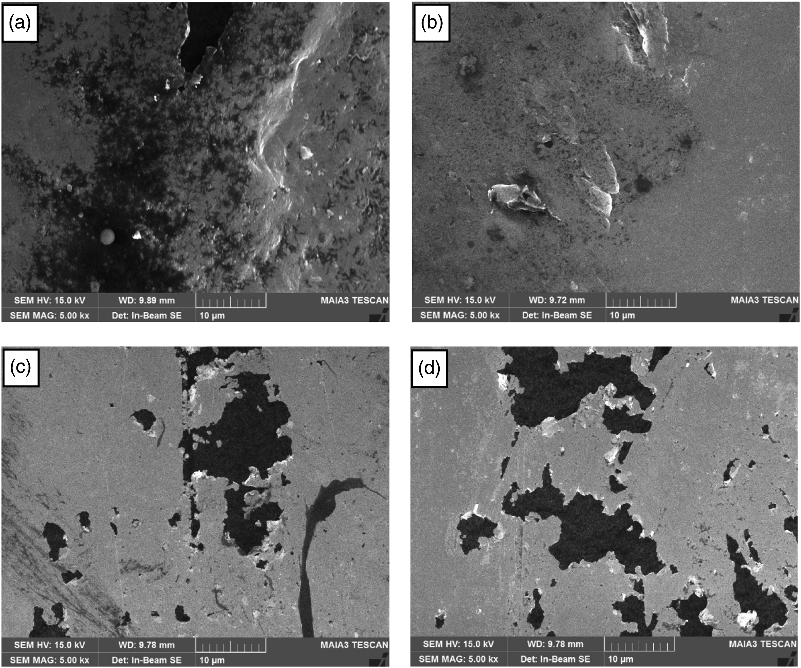

The effect of the large aggregate areas seen in the SEM micrographs (Figures 4 and 5) was also investigated in TGA, one of the most commonly used techniques to evaluate the thermal stability of various materials rapidly. Figure 6 shows TGA thermograms of PA6/MWCNT/CB nanocomposite filaments with different MFR values from room temperature to 600°C. All samples decompose in a single step, and their decomposition mechanism is quite similar—however, the char yield at 600°C in nitrogen increases with increasing MFR. At an MFR value of 3 g/min and 12 g/min, the residue percentage is 9.2% and 14.8%, respectively. It may reason that more carbon-based nanofiller aggregates in the filament section with increasing MFR value. TGA curves for PA6/MWCNT/CB nanocomposite filaments.
The combined consideration of SEM micrographs and TGA thermograms demonstrates that the MFR change significantly affects the structure of the nanocomposite filament. On the other hand, the actions of the extruder screws and spin pumps are complex processes that also influence fiber properties and electrical conductivity. Die swelling is a phenomenon that causes normal stresses to cause the nanofiller-polymer suspension, which is non-Newtonian when it exits the die, to deform the cross-section, as shown in Figure 7. Schematic of die swelling.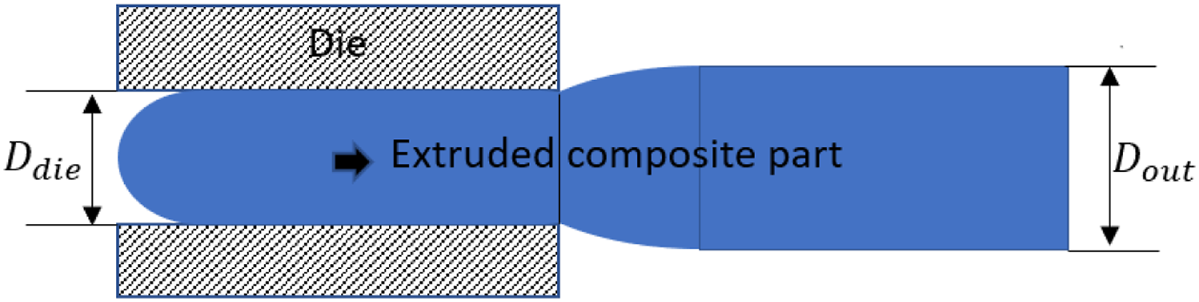
This phenomenon, 50 the Barus effect, is defined by the relation B = Ddie/Dout, where Dout represents the diameter of the extrudate and Ddie the diameter of the die. The MFR is an important parameter that conditions swelling at the exit of the die. The Barus number (B) increases with the flow rate of the melt-up to a break value at which certain flow defects occur. At this break value, B is maximized before it sharply decreases. This threshold value often referred to as “melt fracture, can be characterized by minor irregularities on the surface of the extrusion (roughness, shark skin, etc.), by wavy or helical deformations, or by periodic deformations or fractures (Figure 7).
The fillers at the flow front tend to align along the flow boundary rather than across it, according to an alternative phenomenon
51
related to the flow and melt-spun fibers. The surface tension between the air, polymer, and nanofillers may be responsible for this. But because of this phenomenon, the boundary at every meeting of two flow fronts is known as a weld line. Since the fibers align along the weld line rather than across it, as seen in Figure 8, it is typically the weakest link for the mechanical properties. As a result, addressing and developing flow management strategies to provide strength along the weld lines could be aided by understanding this problem for modelers. Influence of flow on fiber orientation.
Conclusion and outlook
This work aimed to improve a method for systematically developing electrically conductive polymer fibers from nanocomposites produced in a melt-spinning process. This includes the compounding of the base materials, PA6, and electrically conductive nanoparticles such as graphene, CB, and MWCNT into electrically conductive compounds, the melt-spinning of the nanocomposites, and the drawing of the melt-spun fibers.
The systematic development of the fibers is based on a model-based description of the development process, in which the technical and economic aspects are considered, and their characteristic values are quantified and predicted. For the development process, a procedure on several scales (lab-scale and pilot-scale) is chosen. The approach along the process chain on one scale is described with the help of a phase model. The models also enable the probability of success to be assessed and the development duration and costs to be forecast. Following the lab-scale melt spinning experiments, PA6/MWCNT-CB containing 10 wt% nanofiller (each 5 wt%), determined for a pilot-scale melt spinning process in order to investigate the influence of the nanocomposite core material feeding parameters on the properties of melt-spun fibers. The nanocomposite filaments developed have a potential market as polymer-based sensor fibers. Sensor fibers can be used as strain or pressure sensors in medical technology to control body movements and functions. In fiber-reinforced plastics, sensor fibers are primaily used as strain sensors for continuous component control. The correlation between the MFR and electrical conductivity values of PA6/MWCNT-CB nanocomposite fibers, which are influenced by the orientation and the dispersion of the CNT and CB in the PA6 polymers, were discussed. The electrical conductivity decreased by half (from 3.13E-02 to 6.72E-03) when MFR was increased from 3 g/min to 6 g/min but did not significantly change when it was increased from 6 g/min to 9 g/min or 12 g/min for PA6/MWCNT-CB filaments. However, the conductivity values do not change significantly by increasing the melt flow rate from 6 g/min to 12 g/min. This indicates that the extended network formed by one nanofiller is still intact.
SEM micrographs showed that the change in MFR values significantly affected the nanocomposite filaments’ surface properties. As the MFR value increased, the rough and limited agglomeration surface became smoother, and aggregation expanded. This increase in aggregation eliminated the synergistic effect of the CB nanofiller and decreased the electrical conductivity. Besides, defects appeared on the surface when the MFR was increased to 12 g/min.
TGA thermograms of PA6/MWCNT/CB showed that at an MFR value of 3 g/min and 12 g/min, the residue percentage is 9.2% and 14.8%, respectively. It may reason that more carbon-based nanofiller aggregates in the filament section with increasing MFR value.
The combined consideration of SEM micrographs and TGA thermograms demonstrates that the MFR change significantly affects the structure of the nanocomposite filament. On the other hand, the actions of the extruder screws and spin pumps are complex processes that also influence fiber properties and electrical conductivity.
In future experiments, the melt-spinning process should be enhanced to fabricate textile fibers with a higher electrical and mechanical performance by further adjusting the processing parameters and bringing the production to an industrial level to develop battery electrodes and supercapacitors or shielding materials for electromagnetic radiation. This multi-level development process steps forward in applying carbon CNTs, Graphene, or CB nanofiller in the textile industry. The electrical conductive filaments produced in this study should be further processed into textile manufacturing processes, such as woven and knitted fabrics, to investigate the multi-functionality of nanocomposite-based textiles.
Footnotes
Acknowledgements
The author, M.K., acknowledges the support of COST Action CA17107-European Network to connect research and innovation efforts on advanced Smart Textiles (context) for his stay at the Institut für Textiltechnik (ITA) of the RWTH Aachen University, Aachen, Germany.
Declaration of conflicting interests
The author(s) declared no potential conflicts of interest with respect to the research, authorship, and/or publication of this article.
Funding
The author(s) disclosed receipt of the following financial support for the research, authorship, and/or publication of this article: The financial support from the Türkiye Bilimsel Ve Teknolojik Araştırma Kurumu (TUBITAK) BIDEB-2219 Postdoctoral Research Program.