
Abstract
To explore the actual working characteristic of the beating-up mechanism on looms, the Step function is adopted to convert the beating-up resistance to an equivalent torque acting on the rocking shaft, and a new method of calculating and simulating the resistance is hereby raised. In accordance with the two-state joint clearance, the paper establishes a double-side model of the four-bar beating-up system in clearance status via ADAMS/View software, and under the consideration of both beating-up resistance and flexible deformation conditions, the contact simulation of beating-up motion with different clearances (0.01∼0.12 mm) is achieved. The main findings are as follows: the actual working condition could be reflected more accurately if the beating-up resistance and component flexibility are included into the simulation computing; from the perspective of the impact on sley moving and beating-up loads, 0.08 mm clearance is obviously less then another three clearances (0.01 mm, 0.04 mm and 0.12 mm); the multi-point contact and collision with peak load greater than 4000 N is existed in connecting rod bearing in the 0∼350 Hz low frequency area, which is likely to exacerbate the wear and fatigue rupture of the bearing; the dynamic shock load of rocking shaft on the loom frame is far greater than that of the crankshaft, indicating that the rocking shaft is the main carrier for delivering the beating-up power; compared to the clearance of 0.08 mm and 0.12 mm, the dynamic impact load generated by the clearance of 0.01 mm and 0.04 mm on the loom frame is obvious greater. In addition, under the clearance condition, transverse vibration could be occurred for the flexible crankshaft due to the deviation of its centroid trajectory, which is detrimental to vibration and noise reduction for the loom system. On the basis of the work, a number of viewpoints with theoretical and practical significance could be provided to the design of beating-up system on the loom with clearance.
Introduction
In reality, manufacturing and assembly error is unavoidable for any machinery or mechanism, from which the friction wear arises must lead to the transmission clearance caused for kinematic pair, hence, the mechanical transmission without clearance is regarded as an ideal state. 1 For high-speed rotating machinery, the contact collision and shock load caused by joint clearance could not only make the transmission component bear drastic reaction force, but also produce vibration and noise due to dynamic imbalance of the machine body, 2 thereby affecting the improvement of noise pollution of textile factory and physical health of workers.
With the rapid development of modern weaving technology in recent years, more and more requirements of beating-up performance is essential for the new looms. 3 As a common form of beating-up for shuttle and shuttleless looms (like rapier loom, air-jet loom and water-jet loom), four-bar beating-up mechanism is characterized simple structure, easy to manufacture and stable operating, as well as other advantages. 4 The effect of kinematic pair clearance must be taken into account during the process of weaving production, since the four-bar mechanism is mainly connected through the hinge or bearing. The production practices have shown that bearing clearance can cause wear or dynamic stress on key components such as crank, connecting rod and rocker, which can lead to deviation between the actual motion trajectory and ideal trajectory of the sley, thereby greatly affecting the fabric quality, such as cloth oscillation near the cloth-fell, and uneven weft density, etc. 5 Therefore, accurately analyzing and controlling the transmission clearance of four-bar beating-up system is of great practical significance for weaving production.
Through data review and literature search, it was found that there are currently many research results on bearing collision and joint clearance, but few involve the research of textile machinery with clearance. At present, the research on weaving machines with clearance is mainly focused on cam or linkage beating-up, for example: by taking advantage of MATLAB and ADAMS software, Li Y from Tianjin Polytechnic University, conducts the in-depth analysis and simulation research in terms of the conjugate cam beating-up system for rapier loom with clearance 6 ; Chen G and Kou J B from Donghua University, sets up a clearance model for the four-bar beating-up mechanism, which is characterized with continuous contact joint clearance based on the zero-mass bar, and conducts simulation analysis to the kinematics and dynamics characteristics of beating-up 7 ; Hu FX in Suzhou University, establishes the MLSD-based dynamics equation of beating-up system after taking the joint clearance into consideration, and discusses the impact of radial dynamics parameters on counter-force of clearance; 8 Wei Z, Jin GG and others from Tianjin Polytechnic University, adopts finite element method to achieve flexible modeling of the conjugate cam beating-up mechanism, and conducts dynamic simulation analysis on the cam speed, beating-up resistance, structural parameters and so on. 9
Nevertheless, on the premise of mainly adopting the method of rigid body dynamics, previous clearance simulation for the beating-up system could not accurately reflect the actual working status in an objective manner, as they failed to take the member deformation and its contact and collision into account. For this reason, the paper conducts some new research on the four-bar beating-up system with clearance, which helping explore the actual beating-up characteristics on looms.
Inertial beating-up principle
By generally adopting the form of crank-rocker, the four-bar beating-up mechanism tightens the weft yarn through the inertia motion of the sley, with moving members being connected with each other by rotary hinges,
10
as shown in Figure 1, among which, two fixed hinges (point A and D) and two movable hinges (point B and C) are included. When the crank rotates around point A at angular velocity ω, the momentum can be delivered to connecting rod through point B for doing the planar motion. At the same time, the rocker and sley foot move back and forth around point D under the drive of the connecting rod, and then the weft yarn will be pushed to cloth-fell by the reed before forming the fabric. Diagram of four-bar beating-up mechanism.
As for the crank-rocker beating up mechanism, the weaving production practice indicates that since the rocker is regarded as the power member that withstand most loads, the hinge point (point C) between the connecting rod and the rocker undergoes the largest wearing loss during the reciprocating motion of the sley, thereby generating the strongest impact and vibration by the bearing clearance over the axle pin. 11 Hence, it is essential to only reckoning in the axle pin clearance at point C while ignore the bearing clearance at point A, B and D for clearance modeling and simulation computing of the four-bar mechanism.
Two-state joint clearance
Clearance vector model
If any joint clearance existed in the mechanism, the ideal contact between the shaft and the bearing will become loose, from which the contact distortion arising will generate two states in the joints, namely, free motion-contact deformation.
12
When the free detachment is caused by the clearance between axle pin and bearing, their contact state is as shown in Figure 2(a),
13
in this case, the clearance circle radius r could be calculated as per formula (1): R1-axle pin radius; R2-bearing radius. Vector model of bearing clearance. (a) Free state. (b) Contact state.
In another state, the vector model of the joint clearance with contact collision is as shown in Figure 2(b). According to the geometric condition, if the rotation center distance between the axle O1 (x1, y1) and bearing O2 (x2, y2) is greater or equals to the clearance circle radius r, as shown in formula (2), it shows that there is contact collision between the axle pin and the bearing, and the joint at this moment has occurred deformation. On the contrary, given that the center distance


Contact force model
On the basis of the nonlinear equivalent spring damping model, the actual change of the two-state clearance joint can be depicted with two random states, namely, free motion and contact collision.
15
According to mechanical theory, the contact force in generalized coordinates as shown in formula (3): F
n
-normal contact force, δ-normal penetration depth,

Friction force model
In the non-ideal clearance state, the friction resistance torque might affect the connect between the axle pin and the bearing, 16 from which the wear and vibration arising is detrimental to the smooth beating-up of the sley. Hence, in an attempt to accurately calculate and analyze the dynamics characteristics of the bearing with clearance on the axle pin, it is necessary to include the tangential friction into the process of contact and collision.
The modified coulomb friction model is hereby used to characterize the tangential friction force F
t
, as shown in equation (4),
17
in which: v
t
-relative tangential sliding speed at the contact point, μ(v
t
)-coefficient of sliding friction, F
n
-normal contact force.

Beating-up resistance conversion
Thought and method
During the process of fabric weaving, the beating-up resistance on the sley could be decomposed into two parts, namely, the friction resistance and elastic resistance between the warp and weft yarn, 18 which accounts for different proportion respectively at each phase of the beating-up motion. Therefore, the beating-up resistance could be seen as a periodic dynamic load that will change along with the time variable t.
As the reed beats the weft yarn to the cloth-fell with an instantaneous velocity v(t), assume that the uniform distributed beating-up resistance acting on the sley is characterized by q(t), which can be equivalently converted to a concentrated force F(t) according to the mechanical theory, as shown in Figure 3. Under this condition, the force F(t) could be further converted to an equivalent torque M(t) acting on the rotation center of the rocking shaft. Conversion principle of the beating-up resistance.
The conversion method between F(t) and M(t) are as shown in Formulas (5) and (6), in which: L-effective length of the sley, d-the distance between beating-up point and rocking shaft rotation center.


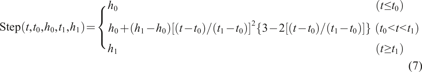
Step function constructing
The ZA205i air-jet loom is produced in collaboration with Xianyang Loom Manufacturing Co., Ltd. and Tsudakoma Industrial Co., Ltd. Its speed ranges from 450 to 700 r/min, the weft density range is between 98.4 to 885.8 pieces/10 cm, and the weft insertion rate is about 1100–1500 m/min. For ZA205i air-jet loom with a width of 190 cm, the maximum beating-up resistance of the sley at the front dead center is about 22.28 N/cm when the loom speed reaches 600 r/min. 19 Given that the length of the sley L = 2.26 m and the distance between the reed beating-up point and the rocking shaft rotation center d = 0.198 m, which substituted into formulas (5) and (6), the maximum equivalent torque that is acting on the sley is approximately 997 N·m upon calculation.
In order to simulate the change of beating-up resistance under actual working condition, the Step function in ADAMS is used to fit the equivalent torque M(t). The Step function is close to Heaviside Step function through cubic polynomials, with its expression as being shown in formula (7),
20
in which: t-independent variable, t0-independent variable value of step starting point, h0-function value of step starting point, t1-independent variable value of step ending point, h1-function value of step ending point.
It can be seen from the change law of beating-up resistance that the force value could reach the maximum when the sley moves to the front dead center, thereby h0 = M(t0) = 997 N·m is obtained. When the sley moves to the rear dead center, the beating up resistance would decrease to 0, that is, h1 = M(t1) = 0 N·m. Taking the front dead center as the initial phase, the Step-function based equivalent torque M(t) expression is constructed as per the above law within 0∼0.3 s, namely:

Equivalent torque fitting
Dimension of the four-bar beating-up mechanism mm.

The SolidWorks software is utilized to conduct the three-dimensional CAD solid modeling and assembly design for each component. The assembly model is imported into ADAMS/View for debugging and editing through the data interface program, including the components name, motion constraints, material properties and appearance. On this basis, the simulation model of the double-side four-bar beating-up mechanism is constructed as shown in Figure 4. The red arrow shown in the figure represents the equivalent torque M(t) that is applied on the rocking shaft rotation center, with its torque direction being consistent with the positive direction of Z axis. The servo motor is installed at the crank end and is mainly used to drive the crankshaft to rotate. As shown by the green arrow in Figure 4(b), ADAMS defines the servo motor through rotational drive during simulation analysis. Virtual prototype of four-bar beating-up mechanism. (a) Double-side view. (b) Single-side view.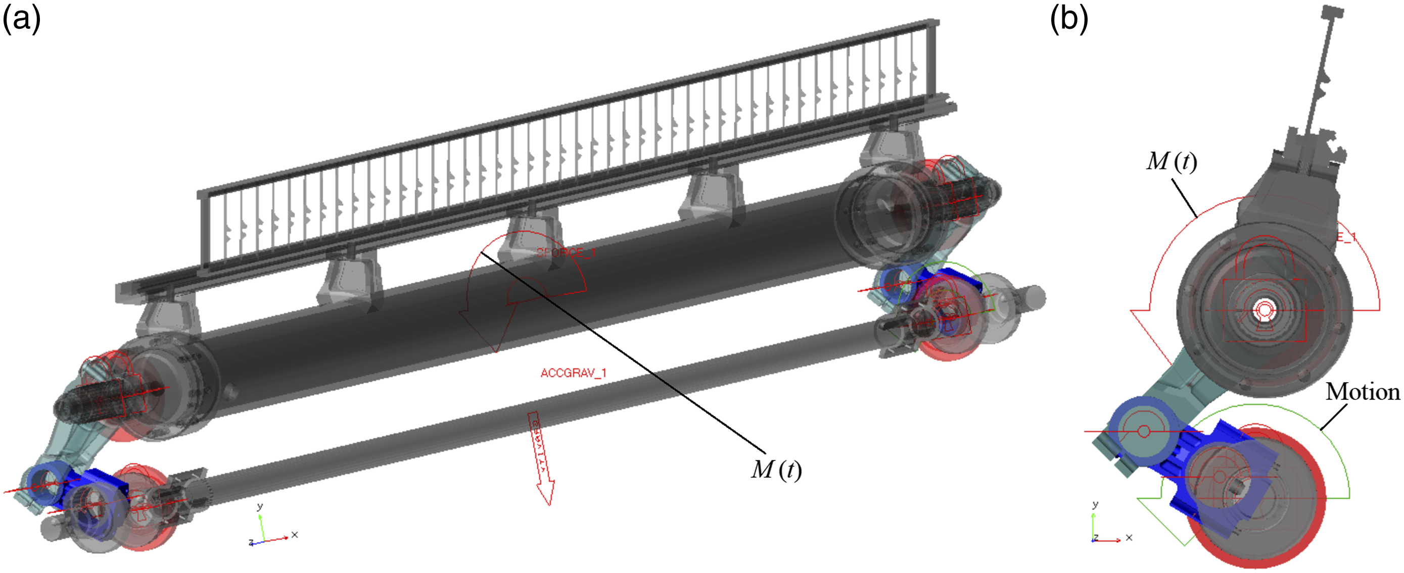
By taking the angle motion law of the sley as a reference, the rigid body dynamics simulation is run with the aim of obtaining the fitting curve of equivalent torque M(t) at 600 r/min, which is as shown in Figure 5. Obviously, the torque M(t) reaches the maximum value (997 N·m) at the front dead center (like 0°, 360° and 720°) of the sley. On the contrary, the value of M(t) rapidly decreases to 0 N·m in a very short time when the sley swings to the rear dead center (like 180° and 540°). It can be seen from that the fitting curve of equivalent torque M(t) and angular displacement curve of the sley enjoy a relatively high matching precision, which could truly reflect the change law of the beating-up resistance. Fitting curve of equivalent torque.
At the position near the front dead center (like 360°), the impact load of the rocking shaft on the loom frame is reduced since the beating-up resistance counteracts part of the inertial force generated by the swing of the sley, which is as shown in Figure 6(a). The equivalent torque M(t) decreases to 0 and the simulated curve overlaps instantaneously when the sley moves to the rear dead center (like 540°), which indicates that there is no influence for the beating-up resistance on the impact load of the rocking shaft and conforms to the four-bar beating-up characteristics during the process of actual weaving. In addition, the beating-up resistance will also have a similar impact on the driving torque of the spindle servo motor, which is as shown in Figure 6(b) and will not give further details. Thus, it can be seen that, the dynamics simulation result of the mechanism is obviously different from the no-load situation while taking the beating-up resistance into consideration. The impact of beating-up resistance on dynamics load. (a) Impact load of the rocking shaft. (b) Driving torque on the spindle.
Flexible modeling
Dynamics equation
In previous relevant studies, the rigid body dynamics simulation could not completely reflect the micro vibration and deformation of the moving components.
23
In order to improve the simulation precision and result reliability of the mechanism, it is essential to take flexible model in the simulation. The deformation of the flexible members in ADAMS/View is depicted by its instantaneous elastic displacement, and compared to the rigid system, the flexible body includes the deformation and stress distribution of the moving members, which could more accurately characterize the actual status of the machinery system.
24
The motion differential equation of flexible body in generalized coordinates is shown in formula (8),
25
which depicts the elastic displacement of moving members through the linear combination of modal vector and modal coordinates.
In formula (8): Q-generalized force, ξ-generalized coordinates, M-mass matrix of flexible body, D-modal damping matrix, K-generalized rigid matrix, ψ-constraints equation, λ-Lagrange factor, f g -generalized gravity.
Structural discretization
Modeling parameters of flexible body.

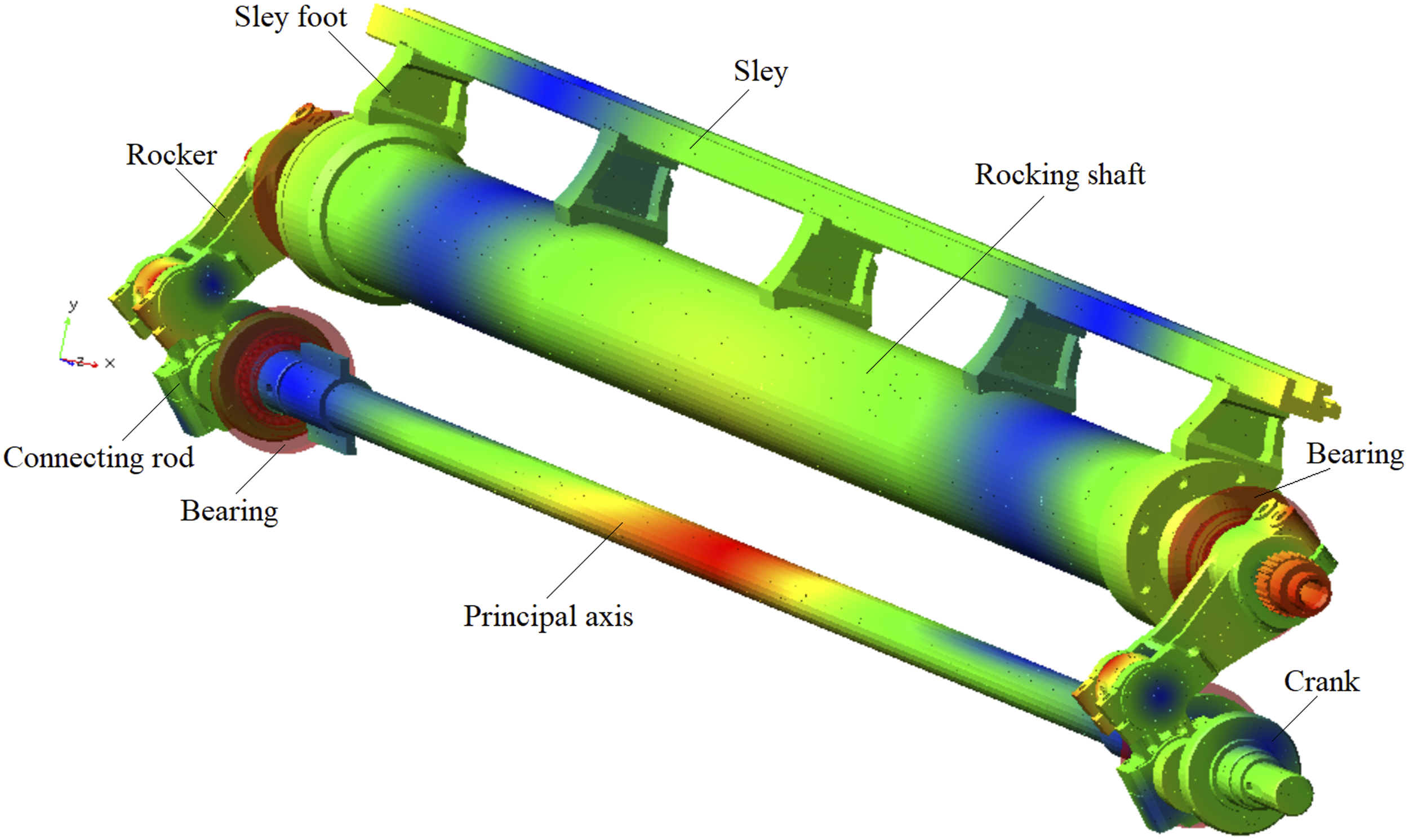
The tetrahedral solid element is used for structure dispersing, and the mesh model of connecting rod, crank and rocker is as shown in Figure 7. These flexible bodies composed of elements and nodes contain the modal information and stress-strain of moving members, which can effectively improve the authenticity of dynamics simulation calculation.
26
The flexible four-bar beating-up mechanism is set up by using flexible body to replace rigid body, as shown in Figure 8, which is the instantaneous simulation pattern of the flexible mechanism in ideal clearance (0 mm). Mesh model of flexible body. (a) Connecting rod. (b) Crank. (c) Rocker. Stress and deformation on the flexible mechanism (0 mm).
Difference of the rigid body and flexible body
The centroid trajectory of the spindle at 600 r/min is obtained while conducting flexible body dynamics simulation under the condition of beating-up resistance. As shown in Figure 9, it can be clearly seen that the centroid trajectory of the flexible spindle and the rigid spindle has significantly deviated, indicating that certain vibration and deformation is occurred on the spindle, which is more consistent with the actual operating state of the loom system. Centroid trajectory of spindle.
Moreover, there is also change for the power transmission of other flexible members, which is shown in Figure 10. The constraint reaction curve under the flexible body is apparently different than that of the rigid body, since the stress and deformation of the crank pin and connecting rod is taken into account. There is no doubt that the simulation curve of the flexible body is closer to the actual state of moving members. Constraint reaction on crank pin.
Dynamics simulation with clearance
Definition of the contact state
Definition of contact parameters.
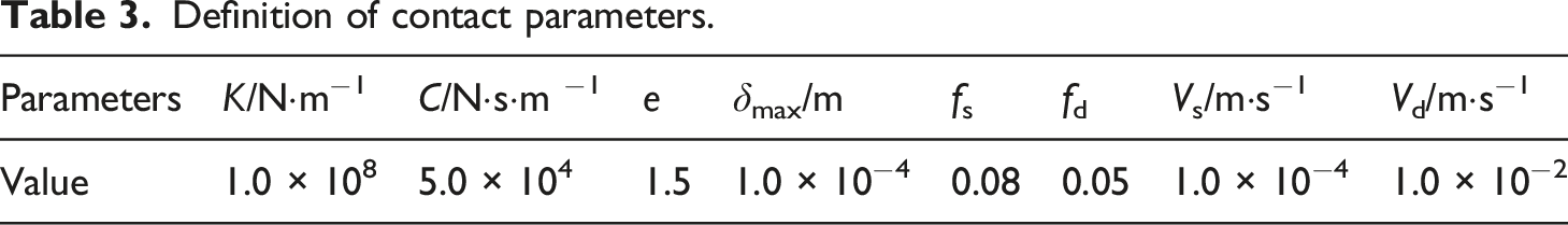
For the Impact function, it takes the Hertz contact theory as the basis, with its expression as shown in formula (9).
28
Given that the Impact function value amounts to 0 under the condition of q > q1, then there is no contact between moving members. In contrast, the Impact function is activated while q ≤ q1, then the contact and collision occur between moving members. During the process of contact force calculation, the Impact function could accurately reflect the contact collision between moving members due to consider the elastic force and damping force.
In formula (9): k-coefficient of contact rigidity, N/m; q-displacement variable of actual measurement at contact point, m; q1-threshold value of displacement, m; e-force index (rigidity contribution factor); cmax-maximum damping coefficient, N·s/m;
Running simulation
According to literature, 29 there is generally less than 15 μm clearance between the axle pin and bearing for the newly manufactured loom. By considering such factors as the assembly error, manufacturing error and material wear of the crank-rocker mechanism, four clearances are set at the axle pin bearing, with the ascending sequence as follows: 0.01 mm, 0.04 mm, 0.08 mm and 0.12 mm, so as to calculate and evaluate the dynamics impact of the joint clearance on four-bar beating-up system.
Given that the rotary speed of the loom spindle is 600 r/min, the simulation time is 0.3 s coupled with steps of 2700 while taking the plain fabric as the weaving object, run the flexible body dynamics simulation under the ideal state clearance (0 mm) and the non-ideal state clearance (0.01 mm, 0.04 mm, 0.08 mm, and 0.12 mm) respectively. As shown in Figure 11, it is the real time simulation pattern for the double-side four-bar beating-up mechanism with flexible clearance, and the arrows there represent the instantaneous contact force and constraint reaction between the flexible members. Simulation of flexible mechanism with clearance (0.04 mm).
The flexible simulation pattern of the crank, connecting rod, rocker and sley could be displayed more clearly from the single side. As shown in Figures 12 and 13, the diverse dimensions of the bearing clearance could result in different status of dynamics load on flexible members. Therefore, there is obvious difference for the instantaneous stress, deformation and contact collision load on flexible members under each clearance at the front dead center and rear dead center, indicating that the joint clearance is an important factor that could directly affect the power delivery of the mechanism. Front dead center position. Rear dead center position.

Result and discussion
Kinematic law of sley
Under the ideal state of zero clearance (0 mm), the kinematic law curve of rigid sley is shown in Figure 14. According to the analysis of the curves, the sley angular displacement is around 28°, which could be seen that the smaller beating-up stroke could effectively reduce the friction between the reed and the warp; near the front dead center (like 360°), the instant angular velocity of the sley at beating-up point is 0, and the negative angular acceleration reaches the maximum (around −82,445.9 deg/s2), which is conductive to inertial beating-up. Besides, the positive angle acceleration reaches the minimum (around 30,163.7 deg/s2) when the sley moves to the rear dead center (like 540°), in this case, the sley is at temporary static state with angular acceleration curve changing in a stable manner, which is helpful for weft yarn insertion and vibration and noise reduction. It can be seen from that the sley kinematics curve matching law is correct and meets the requirements of plain fabric beating-up process. Angular kinematic curve of the sley (0 mm).
When the clearance appears in the axle pin bearing, the sley angular kinematic curve (0.1∼0.2 s) is as shown in Figure 15. It is obvious that deviation and vibration occur for the curves with clearance to the varying extent comparing with the ideal-state curve (0 mm). As the clearance is 0.12 mm, the sley angular displacement deviation reach the maximum, by contrast, there is almost not any deviation for the angular displacement curve with 0.08 mm clearance. From the perspective of fluctuation range and vibration frequency of the angular velocity and angular displacement curve, the clearance of 0.01 mm and 0.04 mm could exert most influence on it, with the value of 0.08 mm being the minimum impact followed by that of 0.12 mm. Angular kinematic curve of the sley under varying clearance. (a) Angular displacement. (b) Angular velocity. (c) Angular acceleration.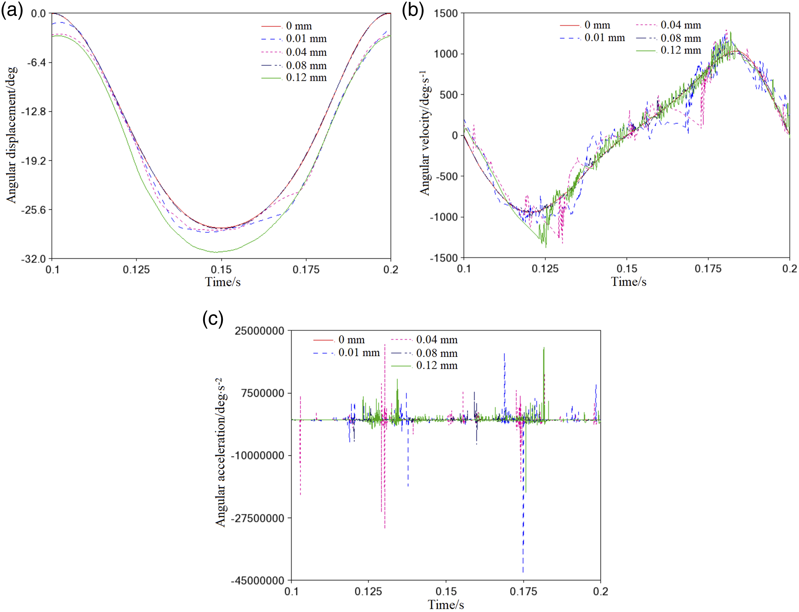
Contact load
With the influence of the joint clearance, the contact collision will inevitably occur between the connecting rod and the rocker. As shown in Figure 16, the contact load in the axle pin bearing is significantly different at each clearance, and among them, multiple instantaneous mutations are existed for the 0.01 mm and 0.04 mm clearance curves, with the maximum load peak being more than 100,000 N, which indicating that the contact load is particularly sensitive to the 0.01 mm and 0.04 mm clearances, and the sley is prone to undergo vibration and impact in the two clearances. Collision force in axle pin bearing.
By contrast, the collision force under the clearance of 0.12 mm is relatively small, and there is not obvious mutation in terms of the curve range and vibration frequency, which shows that the process of contact is continuous and stable. It can be seen from the curve shape that the 0.08 mm clearance curve is the closest to the 0 mm ideal clearance curve, and only slight local fluctuation occurs for the curve, so it will not have too much impact on the collision of the bearing, which is in line with the expectations of the sley angular kinematic analysis.
Spectrum analysis
The load distribution state is calculated in terms of both the time domain and frequency domain, so as to gain a deep understanding of the collision mechanism of the axle pin bearing by 3D spectrum, which is shown at Figure 17. On the basis of spectrum analysis, the contact load caused by the four clearances witness a relatively large mutation in the low frequency region (0∼350 Hz), and their peak load is all greater than 4000 N. Although the clearance of 0.01 mm, 0.04 mm and 0.12 mm could make continuous collisions in the middle and high frequency regions (1000 Hz∼7500 Hz), the peak load of them decreases significantly (<2500 N). By contrast, since the 3D spectrum surface with 0.08 mm clearance is relatively flat in the medium and high frequency regions, the impact of frequency over 1000 Hz can be neglected at this clearance. 3D spectrum analysis. (a) 0.01 mm. (b) 0.04 mm. (c) 0.08 mm. (d) 0.12 mm.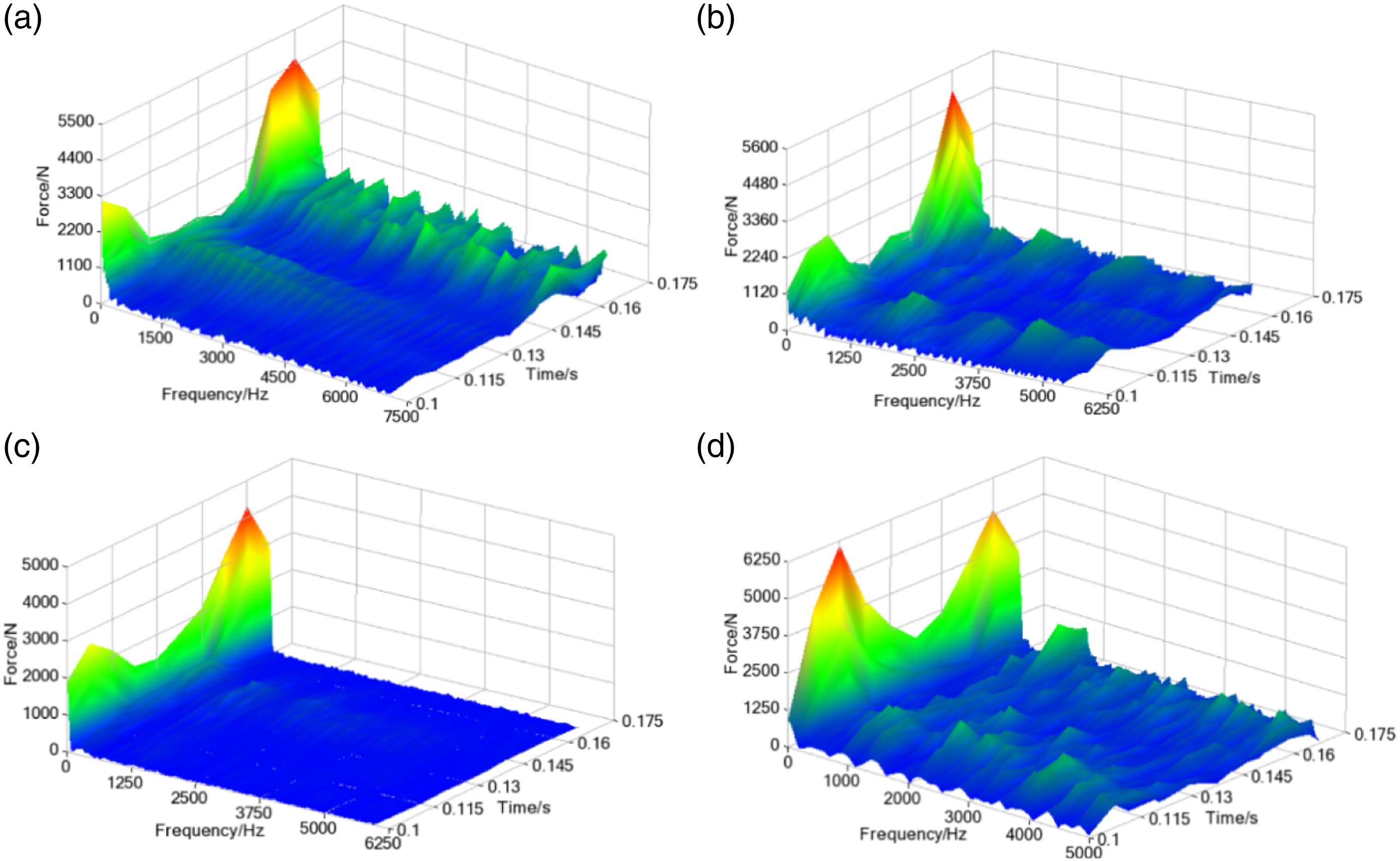
Impact load on the frame
The high-speed reciprocating motion of the sley will generate the periodic inertial beating-up force, and these inertial impact loads will trigger the vibration of loom frame through the rocking shaft or the spindle during the weaving production, which is shown in Figure 18. Under the flexible body of zero clearance, the dynamic impact load caused by the rocking shaft is slightly greater than that of the spindle, particularly the position near the front dead center (like 0.1 s or 0.2 s), and the rocking shaft supporting end would cause greater dynamic impact to the frame since the sley inertia beating-up force reaches the maximum at here. It can be seen from that the rocking shaft bears the main working load during the beating-up motion. Comparison of the impact load on loom frame (0 mm).
Moreover, when joint clearance is existed in the axle pin bearing, the dynamic impact load borne by the frame is shown in Figures 19 and 20. From the perspective of the pattern and vibration frequency of the curves, the impact load acting on the frame shares the similar distribution law with the collision load as shown in Figure 16, except the fluctuation amplitude of the load curve. Therefore, the clearance of 0.01 mm and 0.04 mm exert greater dynamic impact on the frame when comparing to the clearance of 0.08 mm and 0.12 mm, and further details would not be given hereto. Impact load on rocking shaft. Impact load on spindle.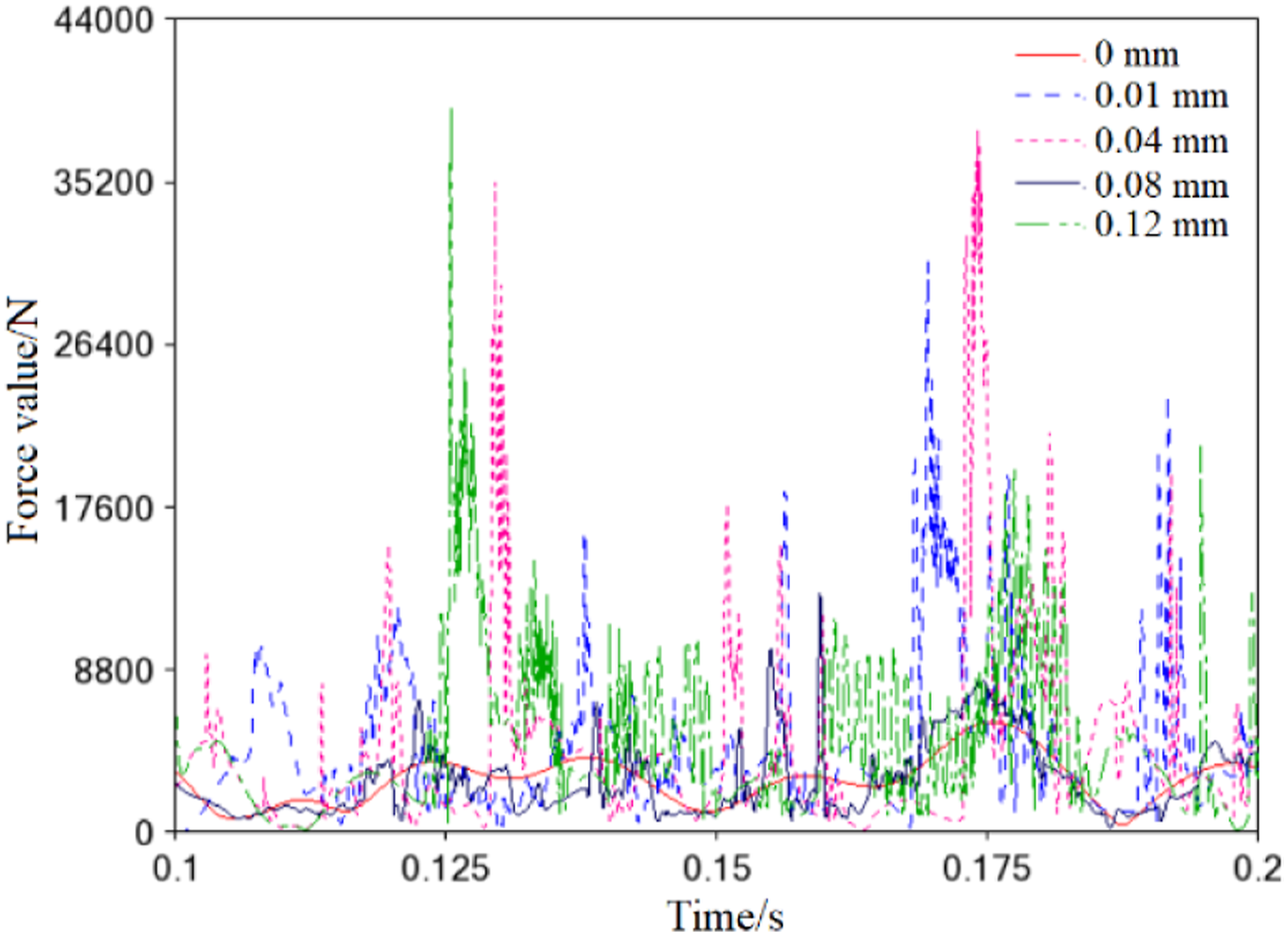

Centroid trajectory of the spindle
In the ideal clearance (0 mm) state, the centroid trajectory of the loom spindle is a standardized circle. When the joint clearance is existed in the bearing system, the centroid trajectory of the spindle is as shown in Figure 21. It can be clearly seen that multiple deviations and overlaps are occurred between the centroid trajectory circle with clearance and the ideal trajectory circle, which mainly because multi-point collisions occurred in the axle pin bearing. The resulting trajectory deviation may easily give rise to transverse vibration of the spindle, which is not conducive to the improvement of fabric quality and weaving efficiency, especially at the high speed, the transverse vibration will substantially affect the operating precision and stability of beating-up. Centroid trajectory of the spindle with clearance. (a) Centroid trajectory circle. (b) Local enlargement.
Conclusion
It is no doubt that, there is a significant practical implication for fabric weaving as the transmission clearance of the beating-up system is controlled in a reasonable manner. By taking the widely used four-bar beating-up system as the research object, the paper proposes a Step function-based method to simulate the beating-up resistance, and realizes the dynamics modeling and simulation of the mechanism while considering the impact of component flexibility and bearing clearance. The result shows that obvious difference is existed between the clearance state and the ideal state in terms of the beating-up characteristics. From the simulation curve morphology, the clearance of 0.01 mm and 0.04 mm has a relatively significant impact on the sley movement, followed by the clearance of 0.12 mm and 0.08 mm. In the low-frequency range of 0∼350 Hz, the clearance of the axle pin bearing may cause a contact collision load with a peak greater than 4000 N. In contrast, the clearance load in the medium to high frequency range (1000∼7500 Hz) has a relatively small impact on the contact collision of the bearing. In addition, high-speed reciprocating motion of the rocker shaft is the main factor causing the impact load on the loom frame, and the dynamic impact load generated by the clearance of 0.01 mm and 0.04 mm is obvious greater than that of the 0.08 mm and 0.12 mm clearance. Compared to the previous dynamics simulation of rigid body that neglected the beating-up resistance, the paper takes the beating-up resistance, mechanism flexibility and bearing clearance into the process of modeling and simulation at the same time. Therefore, the work boasts more reference value on the result precision and reliability, thereby conductive to explore the working performance of the four-bar beating-up system under the actual condition.
Future work
The paper enjoys a precious reference value in the aspect of modeling method and simulation theory, although it doesn’t involve the specific experimental study. In addition, relevant experiments and explorations with reference value have not been detected during the early-stage material consulting and literature retrieval, which is mainly attributed to the pricey cost in experiment of the beating-up system in clearance condition coupled with its technical difficulty and complexity. Nevertheless, the authors are also concerned about and takes interest in the task of doing experiment, who will make use of various available resources to construct the experimental environment with great efforts in the subsequent research work, and in a bid to provide vigorous engineering verification for our work in this paper.
Footnotes
Acknowledgements
Financial support is gratefully acknowledged. We like to thank all the participants and institutions for their technical support as well as all further partners supporting our research work within this application area.
Declaration of conflicting interests
The author(s) declared no potential conflicts of interest with respect to the research, authorship, and/or publication of this article.
Funding
The author(s) disclosed receipt of the following financial support for the research, authorship, and/or publication of this article: This work was financially supported by the Scientific Research Project of Education Department of Shaanxi Provincial Government (grant no. 15JK2177), and also funded by the Special Fund Project for High-level Talents of Xijing University (grant no. XJ20B09).