
Abstract
This study aims to develop composite laminates for the manufacture of prosthesis socket with enhanced mechanical performance. Layered hybridisation of fabrics (i.e. glass, carbon, and Kevlar fabrics) is used to manufacture hybrid composite laminates by resin infusion via vacuum bagging method. The response of these materials to compression loading is investigated by using compression-loading testes and the load-bearing ability was examined by tensile strength tests. Moreover, finite element analysis has been carried out by using the Abaqus software to predict the compressive failure load and damage failure modes for all sockets samples. Experimental results revealed that the hybrid laminates exhibited more stability and higher absorbing energy compared to non-hybrid laminates during compressive loading tests. Furthermore, the hybridisation of fabrics layers can play key role for improving the tensile strength properties of hybrid composite laminates compared to composite laminates without hybridisation. The numerical simulation results of compressive failure load and damage failure modes are in accordance with experimental results qualitatively as well as quantitatively.
Keywords
Introduction
In surgery, the condition of amputation has increased in these days for various reasons such as war, traffic accidents and chronic diseases.1,2 Prosthetic limbs are adopted to replace the missing parts and to perform functions normally with amputee autonomy as much as possible. Although, there is a significant development in prosthetics, many of the amputees either disapprove the prostheses or express the least satisfaction. This is because of socket related issues such as poor comfort, limited biomechanical functionality and hindered control. 3 In this regard, a enormous attention has been paid by researchers to obtain functional and comfortable prostheses. 4 Parameters such as displacements, interfacial stresses, volume fluctuations and thermal discomforts have major influence on the efficiency and acceptability of a socket. 5 Therefore, the prosthesis must be more adequate from safety, durability and mechanical properties point of view. 6 The shape variations and adoption to changes in the volume of the lower limbs should be optimised with structure, dimensions, skin contact and allowance to loads created through gait cycle. 7 Moreover, the prosthetic sockets should have enough strength to bear high stresses expected from the normal pressure as a result of weight and gait leading to the generation of tensile and compressive stress.6,8 Sockets should also be designed as pressure tolerant if the load is mainly applied as result of human body. 9 Selection of materials used in the manufacturing of prosthesis can play role for optimizing the desired parameters. The promising materials for the manufacture of sockets to enhance their performances are composite materials usually constituted from matrix and reinforcement joining at an interface.10–12 Researchers 13–15 have focused on using carbon fibre composites for manufacturing lower limb prostheses because of their excellent properties such as lightweight and high strength and stiffness. Moreover, glass fibre composites showed enhanced comfort properties, excellent mechanical performance and manufacturing reliability.16,17 In order to enable the shape of direct sockets to the patient’s stump, Kevlar fibres have evolved as a good choice if suspended in an ultraviolet curable resin. 18 Nonetheless, the highly expensive composites prosthetics are not always feasible. 11 Only one type of fibre reinforcement (i.e. carbon, glass or Kevlar) may not necessarily provide the best performance for socket. Therefore, selecting a composite hybridised either at reinforcement or resin level can be a workable way out to attain better mechanical and physical performances for socket. Combining multiple type fibres in composite laminates will enhance the performances of composite laminates than that obtained from a single reinforcement.19–25 During walking, shifting of the body weight onto socket structure creates compressive loads that lead to energy storage. Whereas lifting off the body weight results in decompression and it leads to the return of the socket to its original shape; subsequently, the energy is returned. As socket response significantly depends on the weight, height and activity level of patient, it is important to consider the compressibility as main factor in the socket design. 26 The prosthetic sockets users often report discomfort and need to incorporate multiple fittings to a socket to achieve its final shape, and thus it impedes the pace of their rehabilitation. 27 The requirement of advanced technology for the socket design and fitting is acknowledged, so adjustable sockets, sensors and numerical simulations are the effective propositions; 28 however, a limited progress has been seen from lab to practice. A widely adopted simulation technique in engineering applications is the finite element analysis (FEA), for instance, to map the stress distribution or structural deformations. Owing to the complexity of the biomechanical processes being modelled, patient variability across the population and selection of suitable parameters, particular requirements have been raised in the robustness of finite element (FE) models when used for clinical practice and for extracting relevant data.29,30
There is a limited research focused on the tailoring of weight and mechanical properties of laminated composites of sockets. In this regards, a study on optimizing these parameters of composite laminates via multi-fibre hybridisation will be an important addition. By combining the hybrid fabrics such as high tensile strength fabrics (glass and carbon) with Kevlar fabric can improve compressive resistance and absorb energy of compressive loading. Therefore, the objective of this study is to identify a combination of several layers of fabrics in a composite to achieve an improvement in tensile and compressive loading. For this purpose, multiple type fabrics (i.e. carbon, glass, and Kevlar) are used to manufacture sockets. This article also aimed to develop simulation with the aid of Abaqus software for the best practice in FE modelling of prosthetic socket under compression loading. Finally, a comparison of the numerical results of the mechanical behaviour and damage failure mode has been made with the experimental results and the derivations have been made.
Experimental work
Materials
Specifications of resin. 31

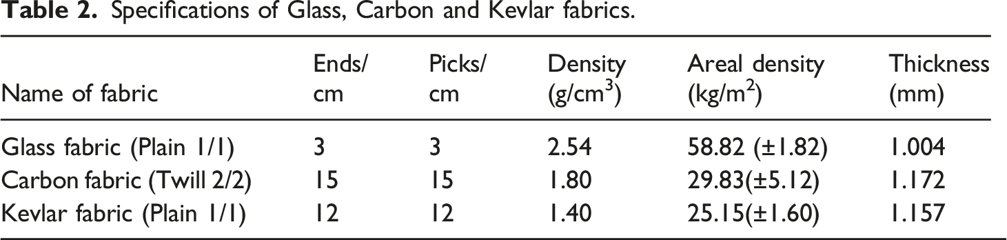
Three types of fabrics (i.e. Glass, Carbon, and Kevlar) are used; the fabrics are shown in Figure 1 whereas their specifications are presented in Table 2. The fabric count (i.e. the number of warp (ends) and weft (picks) in 1 cm), areal density and thickness are measured according to ASTM standards D3775-02, D3776-09 and D1777-09 respectively. Glass fabric (a) and Carbon fabric (b), and (c) Kevlar fabric. Specifications of Glass, Carbon and Kevlar fabrics.
Composite samples manufacturing
Two types of composite laminates have been prepared in this study. The first type is designed as socket samples, while the second type is prepared as flat samples.
In order to prepare socket samples, Jepson mould with suitable dimensions was built and four layers of fabric were wrapped around this mould. After laying up process, the fabrics were sealed with nylon bag and connected with vacuum pump by using pipes. For manufacturing these samples, the Orthocryl lamination and its hardener (80:20) was selected as matrix and 2–3% hardener powders was added by weight of the resin. The fabrics were then infused with resin by vacuum bagging process and cured for around 45 min at 27 ᵒC. The CNC machine was used to clean and cut off extra edges from socket samples. These samples are illustrated in Figure 2 whereas Table 3 presents the weights of these samples. Socket samples made from different types of composite laminates. Mass of Socket samples.

The flat composite samples were made by using flat metal plate cleaned thoroughly with acetone and mould cleaner to produce a smooth surface and coated with mould release wax to remove the infused panel easily. Fabrics with different stacking sequences were placed on the clean metal tool plate and then peel ply was placed under and above the fabrics to facilitate the smooth release of composite laminates from the mesh and from the vacuum bag. Mesh of resin infusion was also used to ensure the uniform flow of resin along the upper and lower parts of the fabrics. PVC feed tubes fitted with spiral delivery tubes were placed on the top and bottom edges of the lay-up to allow the resin to enter and exit the vacuum-bagged panel as illustrated in Figure 3. The interleaved “sandwich” laid laminates were covered by vacuum bagging film sealed to the metal plate using tacky tape. Vacuum was created in the bag with a vacuum pump; the pressure gauge was used to check the vacuum seal by testing for leaks. When the measured vacuum was equal to −1 bar and the pressure gauge was held constant, the lay-up became ready for resin infusion. Process of manufacturing composite laminates.
Three types of composite laminates were made from glass, carbon and Kevlar fabrics without hybridisation by laying four layers of fabrics over one another in each case as seen in Figures 4(a–c). Whereas the other two types of composite laminates were produced by layer hybridisation by placing carbon fabrics on the top and bottom and glass fabrics in the middle of composite laminates in one sample (Figure 4(d)). While placing glass fabrics on the top and bottom and Kevlar fabrics in the middle of composite laminates in the other sample (Figure 4(e)). Table 4 presents the average properties of flat composite laminates used in this study. The density and volume fractions of composite laminates were measured by using the immersion and burning methods according to BS EN ISO 1183-1 and BS EN ISO 1172 standards, respectively. Configurations of Composite laminates. Average properties of composite laminates.

Experimental test methods
Compressive strength tests
In order to investigate the compression resistance of socket samples, the compression strength test was conducted. In this test, the socket samples were held vertically between two jaws of the tensile test machine. The upper head of the test machine was fixed while the lower part of the testing machine was moved upwards by a hydraulic cylinder. As the test started, the sample began to deflect and the compression load-deflection curve was drawn. Figure 5 shows the socket samples during compression loading test. A universal testing machine was used to perform the experiments at room temperature, and the load was applied by moving the lower crosshead at a constant speed of 5 mm/min. Compression loading test.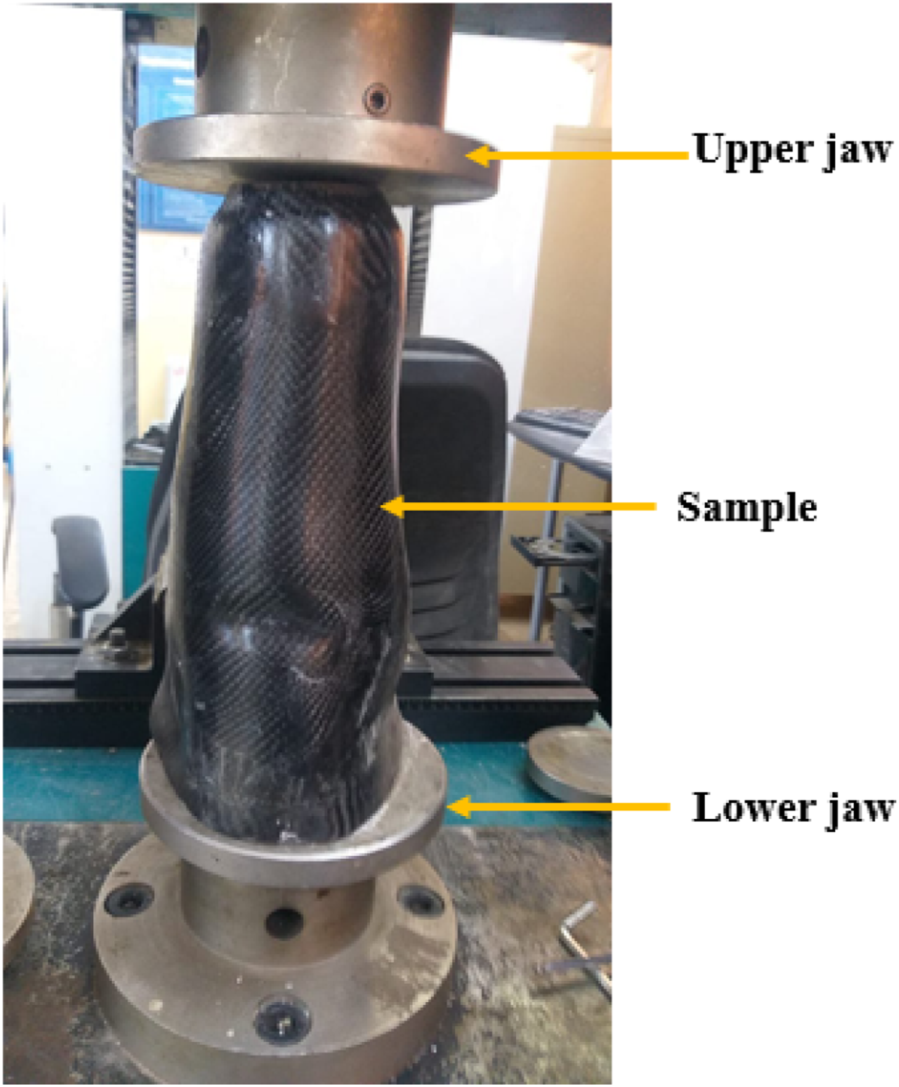
Tensile Strength Tests
In this study, tensile strength tests have been performed to investigate the mechanical properties of all composite laminates. The dimensions of composite laminates were assumed according to ASTM D3039/D3039 M – 08 standard
32
as shown in Figure 6. All types of samples were subjected to tensile load with strain rate equal to 5 mm/min. The tensile strength tests were conducted at room temperature by using a LARYEE universal tensile instrument with 50 kN load capacity as illustrated in Figure 7. Five specimens were prepared for each case. End tabs have been attached to both end of each specimen in order to reduce the gripping effects. The tensile strength (σ) and Young modulus (E) values for each sample were measured by using the following equations. Composite sample for tensile test. Set-up of Tensile strength test.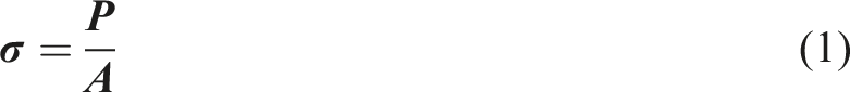


Numerical model
In order to evaluate the behaviour pattern of socket under compression loading, numerical simulations of quasi-static compression loading of socket made of hybrid composite laminates are described in detail. The discrete models are designed in Abaqus 6.14 Finite Element Method (FEM) environment. According to the dimensions are provided from the experimental, applied loading, and observed failure mechanism, the model variants are considered. The following sections describe the FEM models.
Geometric model and materials
Strength properties of Carbon, Glass and Kevlar laminas.


Parameters of the crashworthiness for all composite laminates.

Interactions
The interaction module between two or more objects is one of the most critical aspects of the finite element analysis. This simulation has surface-to-surface contact between the layers of composite laminates when the cohesive zone elements become fully damaged and are removed from the mesh. The friction is also included in this interaction and friction coefficient between surfaces of layers depends not only on the surface quality but also on the interface angle. 34 For instance, the friction coefficient may be low as 0.2 for 0°/0˚interfaces but it can be high as 0.8 for 90°/90° interfaces.
Mesh type
The mesh of each lamina is standard type with continuum shell elements (SC8R) with linear geometric order and the global size is around 0.0008 as shown in Figure 8. Mesh of socket.
Loading and boundary conditions
In FE analysis, the locations of the external forces acting on the socket structure are required to be quantified and specified numerically. Loads are be stated in terms of strength and stump movement. The static load is equivalent to consider only the body weight. While simulating deambulation, the load fluctuates over time that may be quasi-static or quasi-dynamic depending upon the consideration of inertia. The load magnitude is estimated according to body weight or through experimental measurements that require the survey of ground reaction forces and joint angles. In this simulation, the boundary conditions of the model are defined in the Load Module in Abaqus/Explicit assuming that the socket bottom are fully constrained (U1 = U2 = U3 = 0). The height of socket has been restricted only along an out-of-plane direction (U3 = 0) and the load is applied at the top of the socket. Figure 9 illustrates the boundary conditions and load application on the socket. Constraint of socket bottom (a), constraints of the socket edge (b), and (c) direction of load.
Results and Discussions
Results of compressive strength tests
This test was used to investigate the effect of compressive load on the stability and load-carrying capacity of sockets. These sockets were made from composite laminates by infusing tetra-layered fabrics laid over one another with epoxy resin (i.e. orthocryl lamination resin 80:20 with 2–3% of hardener powder) using vacuum bagging technique as shown in Figure 2. During tests, the samples of socket were fixed between the jaws of machine and subjected to an axial compression load in the full load range until the full failure in the samples occurred.
The post-critical characteristics of the structure’s behaviour were determined as a load versus displacement relationship for the full operating range of the structure. Two characteristic load values were determined: the composite damage initiation load
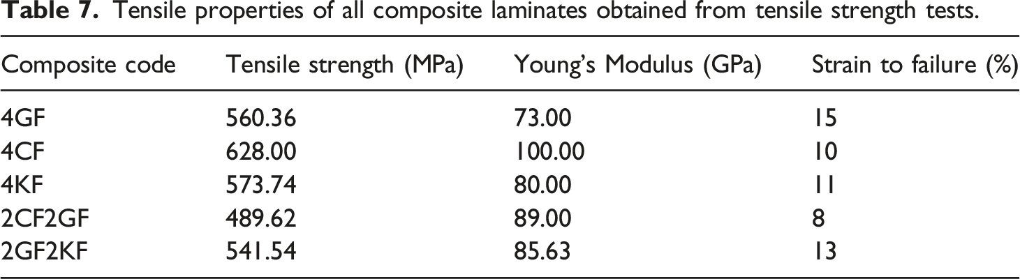
Figure 10 illustrates the load-displacement plots for composite laminates. These curves can be divided into two main portions. The first portion constitutes the elastic behaviour stage and is called as the pre-crushing stage of the socket. Then the initial failure occurs at initial damage strain ( The load-displacement curves for all composite laminates. Tensile properties of all composite laminates obtained from tensile strength tests.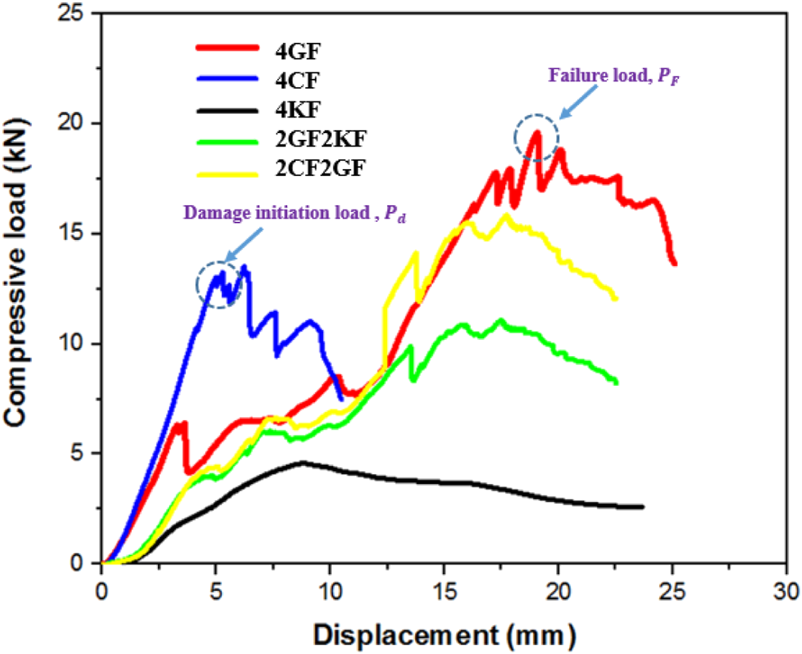
As shown in the Figure 10, initial damage failure of the sample made from glass fabric composite occurred first of all composite laminates at
The carbon fabric sample showed higher compressive load but for short displacement compared to all composite samples. The Kevlar fabric sample exhibited very low compressive load while its displacement showed highest value compared to all composite laminates.
The hybrid composite laminate (2CF2GF sample) showed the highest damage failure load compared to all other composite laminates except glass fabric composite; this indicates their higher stability compared to other laminates.
The ability of composite laminates to absorb energy during compression loading test has been investigated and Figure 11 presents the total absorbed energy for all composite laminates. The total absorbed energy was measured as area under load-displacement curve. It can be seen that glass fabric composite sample showed higher absorbed energy while Kevlar fabrics composites demonstrated the lowest absorbed energy. Moreover, the hybrid composite samples showed improvement in the energy absorption compared to the Kevlar composite sample. Even though the glass composite sample has showed higher absorbed energy, its weight (see Table 4) is still a key issue compared to hybrid composite samples. The total absorbed energy for all composite laminates.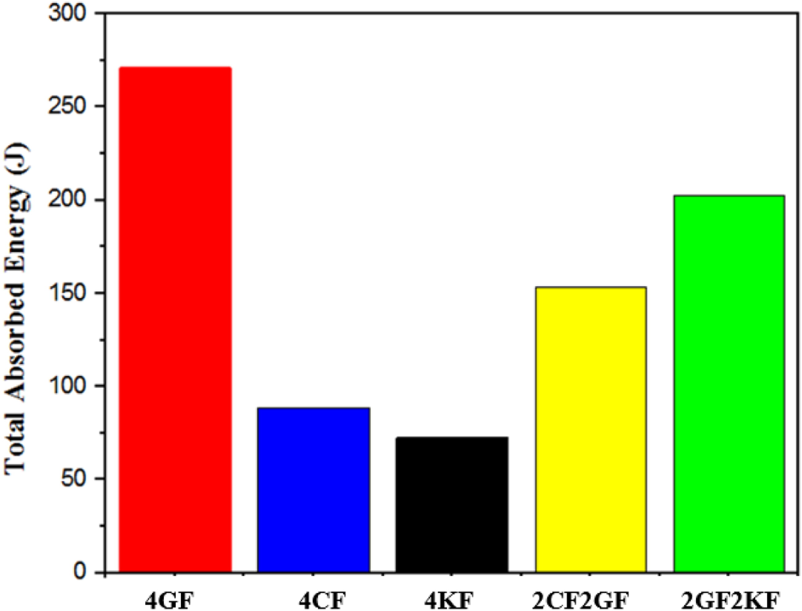
Tensile strength test for composite laminates
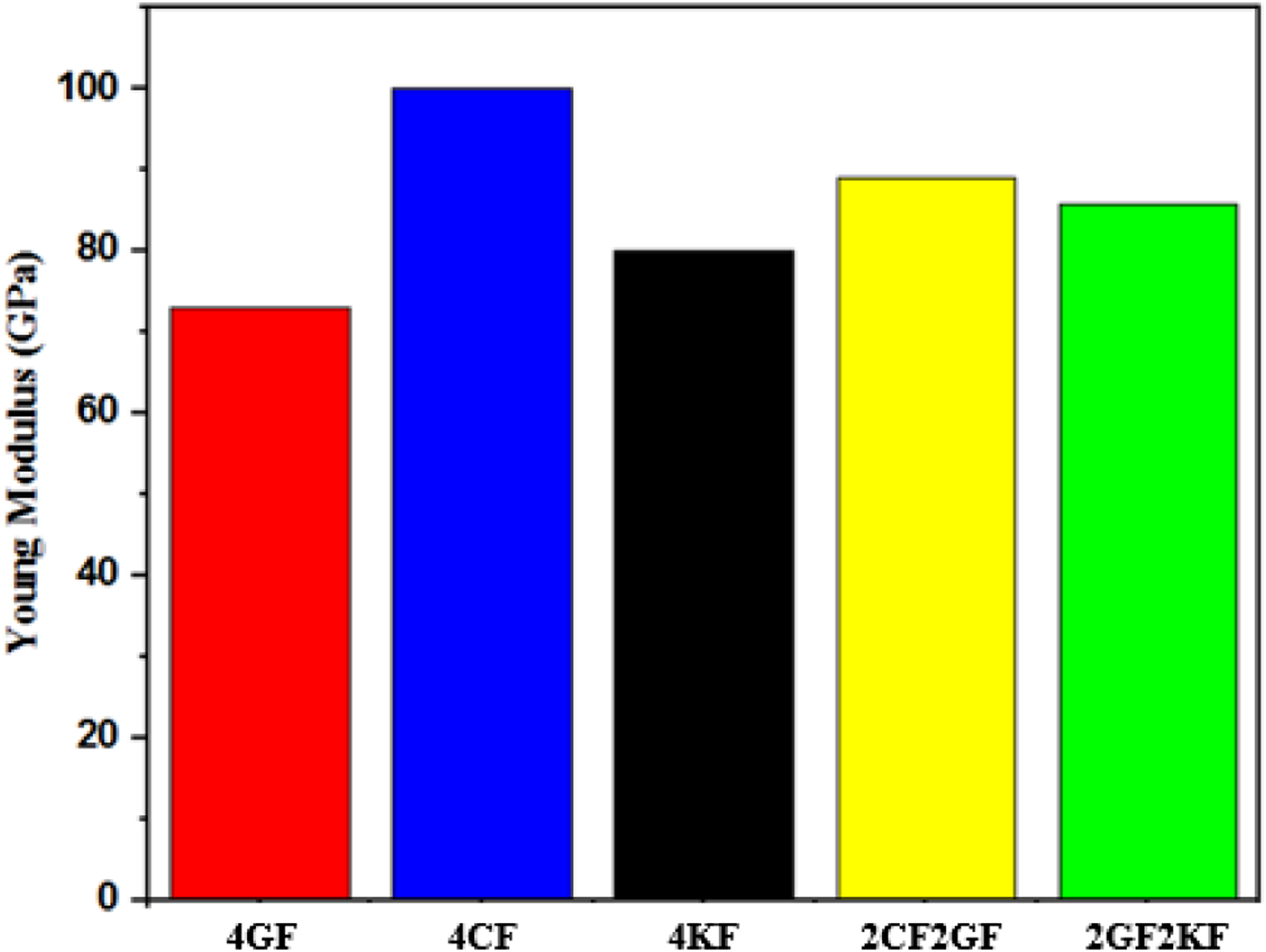
The tensile strength tests have been conducted to evaluate the properties such as tensile strength, Young’s Modulus and strain to failures of all composite laminates as shown in Figure 12 and Figure 13 and Table 8. It can be seen from Figure 12 that the carbon composite laminate showed highest tensile strength and Young’s Modulus than other composite laminates. However, its strain to failure value is less than that of both glass composite and Kevlar composites. Representative stress-strain curves of composite laminates. Young’s Modulus for composite laminates. Numerical and Experimental maximum compressive load of composite laminates.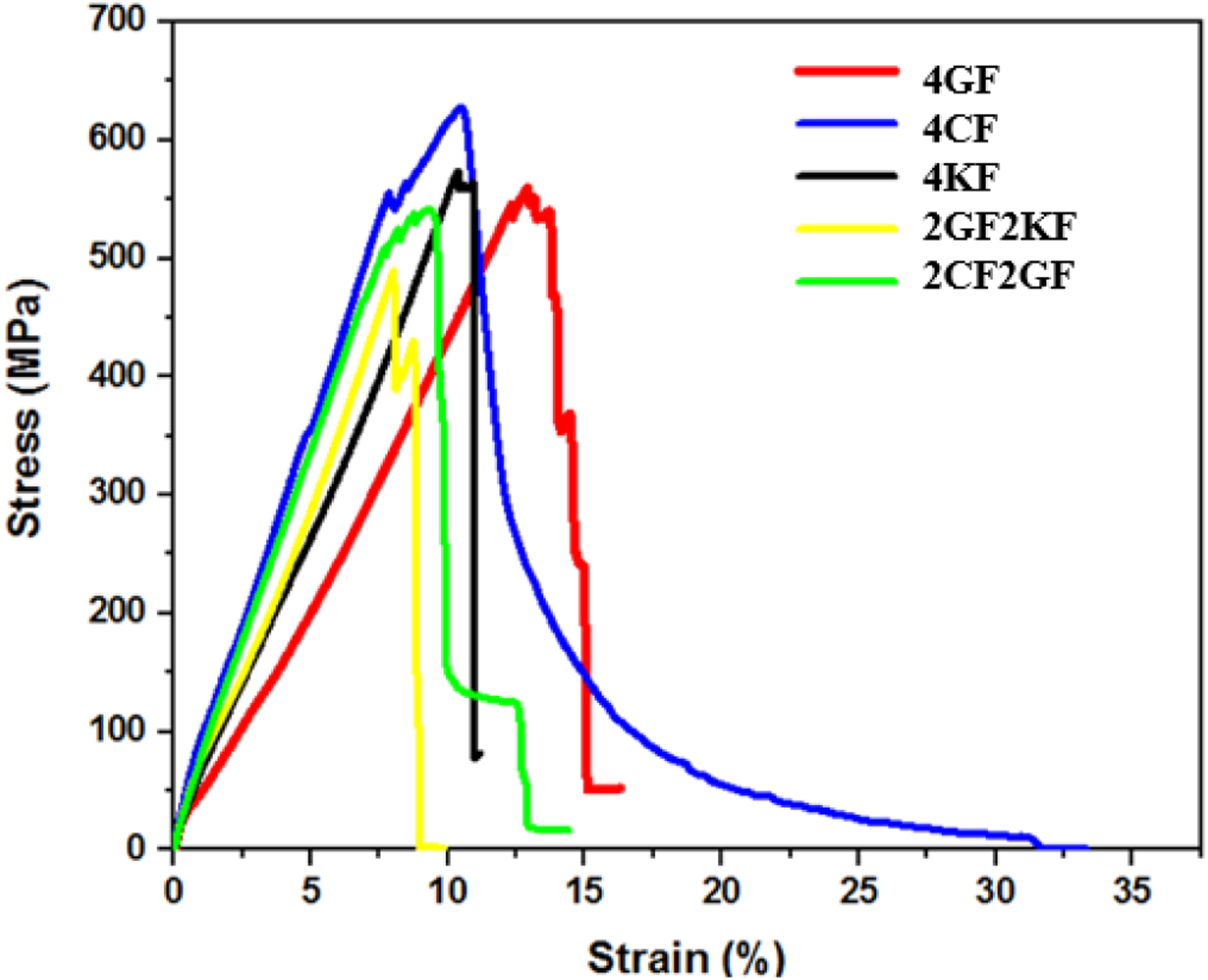

Moreover, the hybridisation of glass and Kevlar fabrics into a composite laminate can improve the tensile strength, Young modulus and strain to failure of the composite compared to glass composite and Kevlar composite separately.
Numerical model validation
The values of compressive loads, which caused failures in all socket samples, predicted by finite element analysis and that extracted from experimental tests are presented in Table 8. The simulation values can clearly be noticed to be in agreement with the data obtained from the experiments with the relative errors ranging within 10%. Moreover, the models so developed predicted slightly lower failure loads in all five cases which is conservative for engineering design.
Figure 14 shows the compressive load-displacement plots for the five socket samples in both numerical and experimental studies. For the socket samples made form glass fabrics and carbon fabrics as shown in Figures 14(a),(b), various load peaks can be observed on the testing plots, which means the fibres in the layers failed under compression loading. Comparing to the numerical results, the compressive load-displacement have one peak loads in whole load phase. Comparison of compressive load-displacement curves of experiments and simulations of (a) 4 GF, (b) 4CF, (c) 4 KF, (d) 2CF2GF and (e) 2GF2KF samples.
A steep load drop can be seen in the compressive load-displacement of socket sample made from Kevlar fabrics (as seen in Figure 14(c)) and this can be attributed to the fibre failure occurred because of bending around the curved region. This behaviour can also be captured from numerical results. The tests results of the socket samples made from hybrid fabrics (2CF2GF and 2GF2KF samples) as shown in Figures 14(d),(e) exhibit that several load distribution occurred prior to the final failure. This can be attributed to the transit of damage failures from matrix cracks to the fibre fracture, which consequently led to absorb more energy.
Figure 15 shows the damage failure modes for socket samples in both simulation and experimental tests. It can be observed that the samples made of glass fabrics and carbon fabrics as shown in Figures 15(a),(b) have reflected the fibre fracture as the main damage failures. Whereas the socket sample made from Kevlar fabrics composite (see Figure 15(c)) has showed delamination with less fibre fractures. Likewise, the FE simulation also captured the same damage failures. Simulation and experimental failure modes of (a) 4 GF, (b) 4CF, (c) 4 KF, (d) 2CF2GF and (e) 2GF2KF samples.
The damage failures of hybrid fabrics sockets (i.e. 2CF2GF and 2GF2KF samples) are presented in Figures 15(d),(e) and the dominant damage failures are delamination and matrix cracks with less fibre fractures.
Figure 14 and Figure 15 evidenced that the FE model could predict the compressive failure load and the failure mode well in comparison with compressive load-displacement plots and the failure modes extracted from the investigated experiments.
Conclusions
Aiming to improve the performances of prosthesis sockets, experimental and numerical simulation have been carried out to study the influence of hybridisation on the mechanical performances of prosthesis sockets. The hybrid socket samples and flat composites samples have been carefully made from various types of fabrics (i.e. glass, carbon, and Kevlar fabrics) via vacuum bagging process. The response of these materials to compressibility was investigated by using compression-loading testes whereas the load-bearing ability was evaluated by conducting tensile strength tests. The Finite Element Analysis using Abaqus software has been adopted to predict the compressive failure load and damage failures modes for all sockets samples. The following conclusions can be drawn from the current study. • During compression loading tests, the hybrid composite laminates (i.e. 2CF2GF and 2GF2KF samples) exhibited more stability (i.e. initial damage displacement and final damage displacement are higher). Furthermore, their energy absorption were higher compared to other composite laminates except glass fabrics sample • Hybridization played a significant role for improving the tensile strength properties of hybrid composite laminates (such as made from glass and carbon fabrics and glass and Kevlar fabrics) compared to composite laminates without hybridisation except glass fabrics sample. • Experiments and FE simulations were carried out for prosthesis socket under compressive loading. The numerical results and failure modes have a good agreement with those from testing. Thus, the simulation model can be used to predict the compressive failure load and failure mode of sockets made from hybrid composite laminates.
As noticed in this study, the combination of various types of fabrics can effectively be used for manufacturing hybrid composite laminate of the socket. These materials can potentially be tailored for achieving high compressive loading and tensile strength with light weight compared to the heavy composite laminates such as glass fabric composite laminates.
Footnotes
Declaration of Conflicting Interests
The author(s) declared no potential conflicts of interest with respect to the research, authorship, and/or publication of this article.
Funding
The author(s) received no financial support for the research, authorship, and/or publication of this article.