
Abstract
Fiber Metal Laminates (FML) are structures that contain a sequential arrangement of metal and composite materials, which are of great interest to the aerospace sector due to the superior mechanical performance. The traditional manufacturing process for FML involves considerable investment in manufacturing resources depending on the design complexity of the desired components. To mitigate such limitations, 3D printing enables direct digital manufacturing to create FML with customized configurations. In this work, a preliminary mechanical characterization of additively-manufacturing-enabled FML has been investigated. A series of continuous glass fiber-reinforced composites were printed with a Markforged system and placed between layers of aluminum alloy to manufacture hybrid laminate structures. The laminates were subjected to tensile, interfacial fracture toughness, and both low-velocity and high-velocity impact tests. The results showed that the FMLs appear to have a good degree of adhesion at the metal-composite interface, although a limited intralaminar performance was recorded. It was also observed that the low and high-velocity impact performance of the FMLs was improved by 9–13% relative to that of the constituent elements. The impact performance of the FML appeared to be related to the fiber fracture, out of plane perforation and interfacial delamination within the laminates. The present study can provide an initial research foundation for considering 3D printing in the production of hybrid laminates for static and dynamic applications.
Keywords
Introduction
Fiber Metal Laminates (FML) are layered structures constructed of stacked arrangements of metal and fiber-reinforced composites. Over the last decade, systems such as GLARE (glass-fiber-reinforced aluminum) have been extensively used in aerospace applications in parts such as fuselage, wings and tail, due to the combination of metal durability and machinability combined with the high-performance fatigue and fracture properties of composite. 1 The aluminum 2024-T351 is still broadly used in the fuselage section of aircrafts due to its tensile strength and lightweight features. It has been reported that Al 2024-T351 has a tensile strength of 462 and 455 MPa, in the longitudinal and transversal directions, respectively. 2 Similarly, its yield strength has been reported as 344 and 310 MPa, in the longitudinal and transversal directions, respectively. 2 However, GLARE has shown 30% of cut weight over aluminum, and therefore it is used in aircrafts such as the Airbus 380. For instance, GLARE 3 (FML based on cross-ply glass fiber composite) has shown a tensile strength of about 717 MPa in both the longitudinal and transversal directions, with an Elastic modulus of 58 GPa. 3 This FML has also shown a shear yield strength of 154 MPa for unidirectional arrangements, and 129.4 MPa cross-play configurations. 4 GLARE 3 has also displayed a critical shear flow for initial buckling of 300 N/mm. 5 This FML has also shown minimum cracking energies of 37 and 93 Joules, when subjected to low and high-velocity impact tests, respectively. 5 Under dynamic conditions, the residual strength of riveted lap joints based on FML has supported more than 70000 fatigue cycles when subjected to a stress of 100 MPa. 6
These mechanical properties have promoted many studies under static and dynamic conditions. Krishnakumar 3 demonstrated that the combination of a cross-ply glass-fiber composite and an aluminum alloy (2024-T3) surpass the mechanical properties of traditional plain carbon-fiber-reinforced composites. Vogelesang and Gunnink 7 performed fatigue tests on FML in comparison to plain aluminum alloys and demonstrated that the growth rates of crack in the stacked systems were between 1% and 10% of that in aluminum alloys. The fatigue tests performed by Meng et al. 8 showed that the fiber bridging mechanisms reduces the crack propagation on FMLs. Roebroeks 9 compared the residual strength of lap joints based on GLARE and concluded that these joints are superior to those reported on aluminum 2024-T3. Similarly, Vlot 10 showed that GLARE offered a superior increased damage threshold performance under low and high-velocity impact conditions when compared against monolithic aluminum alloy. In fact, the failed GLARE impacted samples indicated that the fiber fracture threshold energy was higher than the required to fracture the farthest stacked aluminum layer along the projectile path. Low and high-velocity impact studies have been conducted on FMLs under different stacking conditions, and it has been concluded that damage can be predicted using the areal density of the FMLs and threshold energies obtained from the ballistic tests, drop weight tests or integrated models.11–14 Wu et al. 15 have shown that tensile properties of FMLs can be easily predicted by using a simple rule-of-mixtures. Lawcock et al. 16 investigated the effect of the fiber/matrix adhesion on the impact properties of a carbon-fiber-reinforced FML, and they showed that surface treatments could reduce the fiber/matrix splitting impact mechanism, in addition to an improved residual tensile performance in the laminates. Li et al. 17 conducted a study to determine the effect of adhesive quantity on the mechanical properties of aluminum-lithium alloy based FMLs and found that the tensile strength can reach around 580 MPa with 40 g/m2 of adhesive, while the flexural strength can reach around 610 MPa with 60 g/m2 of adhesive. Trzepiecinski et al. 18 also conducted a study to determine the effect of adhesive film in an aluminum/glass fiber-reinforced laminate and found that the peel strength of FML significantly increased by 289.4% when an adhesive film is used between adherend and prepreg.
In the traditional manufacturing of the hybrid fiber metal composite systems, the relatively longer curing times of the thermosetting matrix posed a major disadvantage. In principle, this problem has been overcome by using a thermoplastic-based composite which is relatively easier to mold and bond to the metal substrate. Indeed, a simple one-shot manufacturing operation can then be used to obtain the required shape.19,20 This procedure clearly reduces both the associated manufacturing costs and cycle time. However, the production of FML with complex shapes requires the use of molds and elaborated manufacturing steps.21,22 An alternative process could be the inclusion of additive manufacturing in which customization for improved performance can be achieved. Several additive manufacturing techniques have been explored as a potential replacement for more traditional manufacturing techniques such as injection molding and are finding firm footing on applications ranging from composite reinforcement manufacturing and nanocomposite studies to the development of rheological studies for tooling on big area additive manufacturing.23–27 Across the seven additive manufacturing processes currently available, Fused Filament Fabrication (FFF) is a low-cost 3D printing technology that can be used to rapidly print composites directly from computer aided design (CAD) models without specific hard tooling. Although most of the recent composites manufactured via FFF are mainly focused on chopped fiber reinforcement, and several works have incorporated the use of continuously reinforced fibers. Tian et al. 28 reported tensile strengths up to 256 MPa for PLA with continuous carbon fiber reinforcement. Similarly, Dickson et al. 29 reported a tensile strength of about 206 MPa on 10% volume glass fiber-reinforced Nylon samples. These mechanical properties seem to indicate that promising FML can be manufactured based on 3D printed composites. This research study investigates the tensile, fracture and impact properties of FML based on continuously reinforced 3D printed glass fiber composites manufactured by the Markforged system. The aim of this work is to present a preliminary insight into the mechanical behavior of FML based on 3D printed composites on which new performance optimizations can be explored on hybrid laminated structures for static and dynamic loading conditions.
Experimental methodology
FML manufacturing process
In this work, a Mark Two® 3D printer from Markforged, a company that provides end to end 3D printing solutions, was used to print unidirectional (UNI) and cross-ply (CP) continuous glass fiber (GF) composites. The composite was constituted by six layers of printed materials where each layer had an average layer thickness of 0.1 mm. The four inner layers consisted of continuous glass fiber printed at 252°C and the external layers of a proprietary Markforged material known as ONYX printed at 275°C, which is based on a mixture of chopped carbon fiber and nylon as represented in Figure 1a. with about a 0.4 mm dual nozzle system. It is worth mentioning that the ONYX layers are printed in 45° orientation by default on the Mark Two® printer.
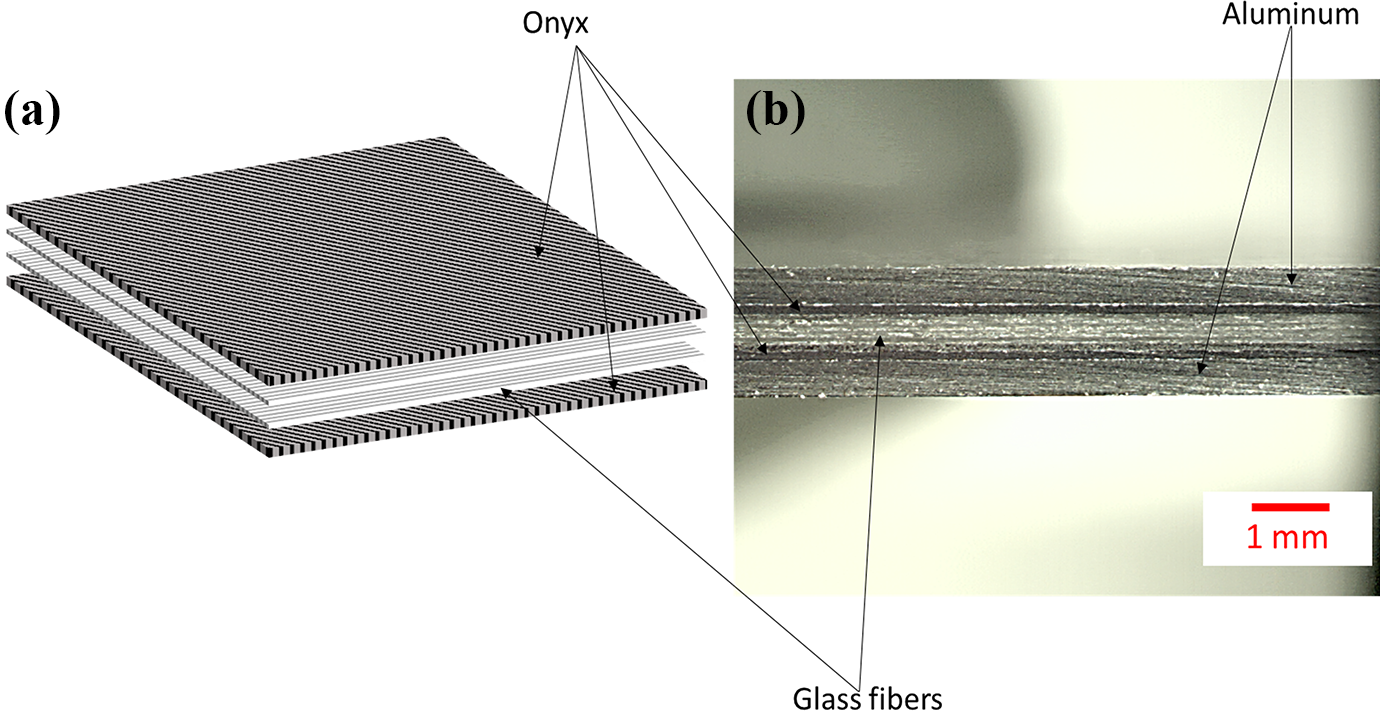
Investigated systems: (a) schematic of the 3D printed composite, (b) assembled fiber metal laminate.
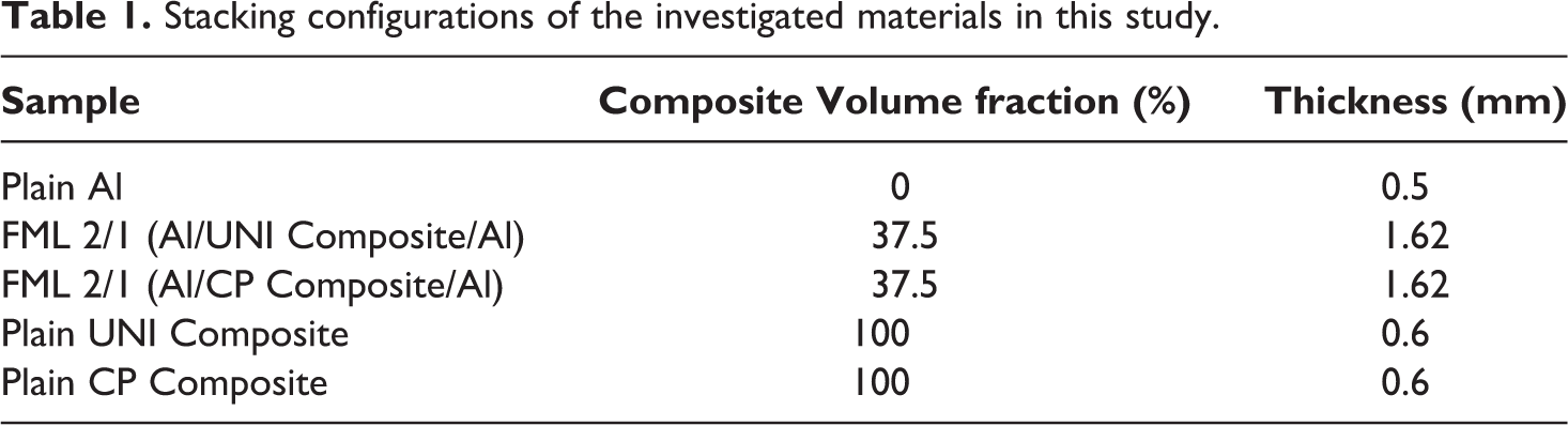
The printed composites were subsequently sandwiched between layers of aluminum alloy 2024-T3 to consolidate the FML (see Figure 1b). The FML investigated in this work were based on a 2/1 stacking configuration. The first and second digit indicates the number of metal and composite layers, respectively. Table 1 shows the composite volume fractions of the investigated FML.
Stacking configurations of the investigated materials in this study.
The composite-aluminum adhesion was improved by placing a 0.1 mm thick modified polyethylene film (Bemis 6343) at each metal-composite interface. All inner metal surfaces were slightly sanded down by hand with a 180-grit sandpaper to improve the adhesion. Gonzalez-Canche et al. 30 showed a significant metal-composite bonding enhancement on sandpaper grinded alloy layers on FMLs when compared to degreased/non-grinded samples. After the sanding process, the metal was cleaned with isopropyl alcohol to remove all impurities. The materials were then placed in a square mold with inner dimensions of 10 cm × 10 cm with the metal rolling direction aligned in the same orientation of the 0° printed fibers. The stacked system was then placed in a hot-press at 160°C and 2 bars for 1 hour. After this time, the heat was turned off under constant pressure until the sample reached room temperature (with a cooling rate approximately 1.8°C/min). The samples were then removed from the press and the mold.
Tensile test
The tensile tests were conducted on an Instron 5500R at room temperature based on the ASTM D638/Type IV (100 mm length and 6 mm width) for the FMLs, the ASTM D3039 (100 mm length and 15 mm width) for the composites, and the ASTM E8 (100 mm length and 6 mm width) for the plain aluminum alloy. At least three samples were tested for every investigated system. The load–displacement curves provided by the Instron system were used to create the stress–strain graphs from every tested sample.
Interfacial fracture toughness
The interfacial fracture toughness tests were also conducted on an Instron 5500R at room temperature under quasi-static loading conditions, following the protocol for interlaminar fracture testing No. 3 from the European Structural Integrity Society Polymers & Composites Task group, which is also used by other studies.31–35 The fracture toughness was evaluated using a 100 mm length and 20 mm width single cantilever beam (SCB) configuration as shown in Figure 2. An aluminum insert was incorporated between the adhesive layer and the aluminum to act as a crack initiator located at 20 mm from the end. On the SCB specimens, quick-dry white liquid paper was applied along the length of the sample and a scale was drawn on it to follow and register the crack propagation.
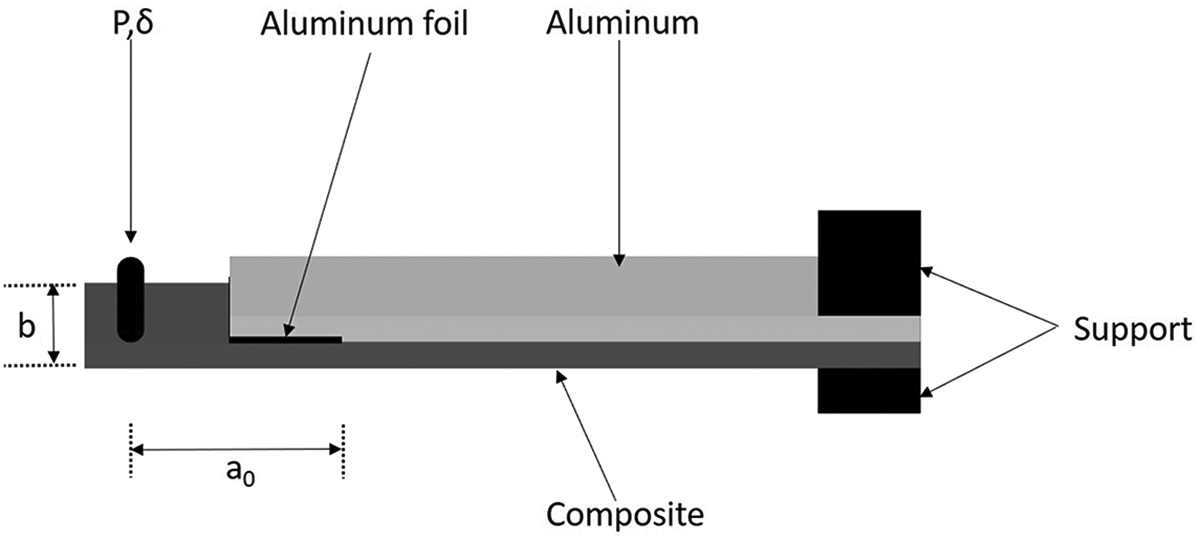
Schematic of the single cantilever beam test geometry.
The SCB samples were clamped at one end in a steel fixture and loaded at a cross head displacement rate of 2 mm/min.The interfacial fracture energy, Gc was calculated using Equation 1 32 :
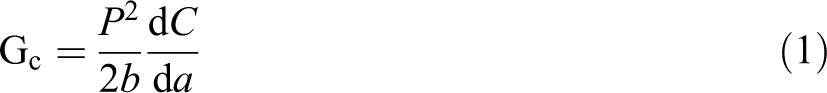
where P is the applied force, b is the specimen width, C is the specimen compliance, and a is the crack length. The specimen compliance in this case was determined from Equation 2 32 :

where C0 and k are constants for a given specimen, in which k was determined by measuring the slope of the graph of the compliance C versus the cube of crack length.
Low-velocity impact tests
Low-velocity impact tests were conducted in a falling-weight impact tower, which was instrumented with a 50 kN dynamic Kistler load cell as represented in Figure 3. To induce different impact energies, impactor masses of 1.397 kg and 8.896 kg were dropped from different heights, and consequently, the impact energies were varied. The samples were clamped on an 80 mm diameter circular steel ring and impacted at their center by an impactor with a hemispherical tip of 15.7 mm in diameter. The tests consisted of performing a series of impacts with energy increments and then correlating the changes observed in the force–time curves with the damage exhibited by each material.
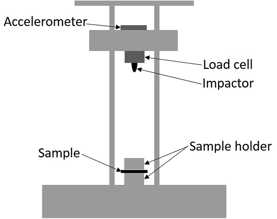
Schematic of low-velocity impact setup.
High-velocity impact tests
High-velocity impact tests were conducted using a gas gun apparatus to study the dynamic performance and perforation resistance of the investigated sample (see Figure 4). Spherical stainless-steel balls of 7.94 mm diameter with a mass of 2.05 g were used as projectiles in a compressed nitrogen gas gun. After firing, the projectile passed through a CED M2 chronograph for measuring the velocity before impacting the samples. A systematic increase of the impact velocity (by increasing the pressure in the gas gun) was employed until the energy necessary for perforation was obtained. A new, non-impacted sample was used on each high-velocity testing.
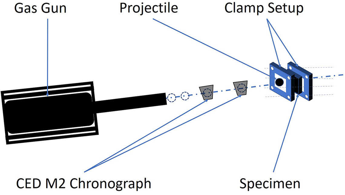
Schematic of the gas gun apparatus used for the high-velocity impact testing.
Results and discussion
Tensile test
The averaged stress–strain values of the tested materials are shown in Table 2. During the testing, it was observed that the plain 3D printed composites and the FML show a relatively linear response up until their tensile strength, followed by a brittle failure. In contrast, the plain aluminum alloy displayed a characteristic yielding point about 250 MPa followed by a ductile profile until the ultimate tensile strength was reached, which was about 440 MPa. From Table 2, it is observed that the tensile strength of the FML seems to fall between the strength of the constituent materials, where the 2/1 UNI-FML shows higher strength than its counterpart (2/1 CP-FML), mainly due to the fully aligned glass fibers at the testing direction (0°). Similar tensile strength values have been shown on FML based on GF-polypropylene with volume fractions in the same range as those investigated in this work. 32
Averaged stress-strain data of the materials investigated in this work.
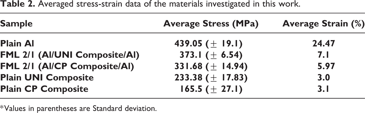
* Values in parentheses are Standard deviation.
An analysis of the fractured tensile samples was also performed and shown in Figure 5. The figure shows that the unidirectional composite presented only longitudinal splitting along the fibers due to the low strength provided by the thin ONYX layer for keeping the fibers compacted as a whole system. Similar results have been observed in unidirectional composites under tensile testing conditions. 36 A splitting mechanism was also observed on the 3D printed CP composite; although in this case, the splitting was observed in the 0° and 90° orientations. Included in Figure 5 is the fracture micrograph of the FML 2/1 where a complete failure across the metal and composite layer was observed. A further inspection of the tested 3D printed composite shows a delamination between the ONYX and GF layers, suggesting that a better printing process must be incorporated when manufacturing the samples to improve the fiber-ONYX intralaminar adhesion.
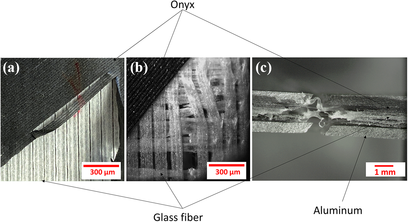
Micrographs of fractured tensile test specimens: (a) pure composite UNI, (b) pure composite CP, (c) 2/1 FML.
Interfacial fracture toughness
A typical load–displacement curve of the investigated SCB samples is shown in Figure 6. From the figure, it is observed that the initial loading displays an elastic profile until the point where the fracture starts propagating through the composite-metal interface, at a load value of 48 N. This profile has been reported by other researchers on bi-material systems. 37 Figure 7 shows a representative interfacial fracture toughness Gc of the aluminum-3D printed composite in which the initial value started at approximately 640 J/m2, followed by an increase as the crack propagation increased. The results showed that the samples reached a plateau around 1100 J/m2, an interfacial fracture toughness value of about three times lower than that reported on other thermoplastic-based FML. 38 These results can be related to a low ONYX-glass fiber adhesion, and to the delamination between the glass fiber layers.
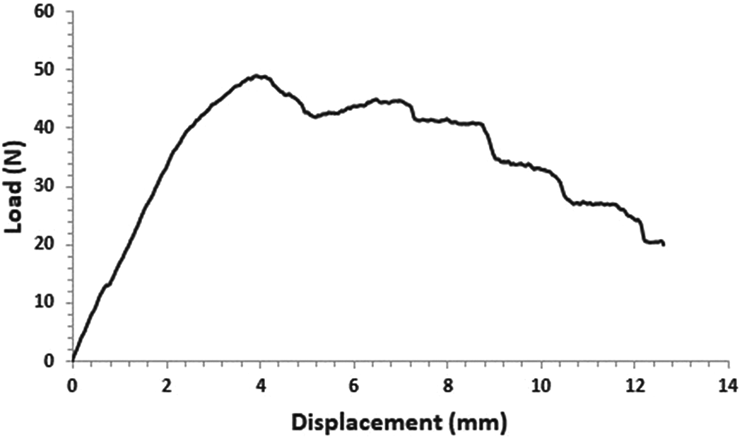
Representative load–displacement curve of the 3D printed GF composite and aluminum alloy.
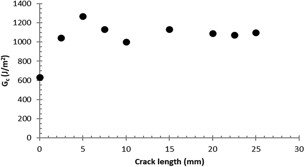
Interfacial fracture toughness of the aluminum and 3D printed composite at the crosshead displacement of 2 mm/min.
Optical analysis of the fractured SCB specimens showed that the fracture occurred between the glass fiber layers and the ONYX material (see Figure 8). From the figure, it is observed that only some residual ONYX remained attached to the aluminum after completing the SCB testing, suggesting that further optimization is required to be incorporated when printing fully continuously reinforced composites on the Markforged system, so that the intralaminar adhesion can be strongly improved.
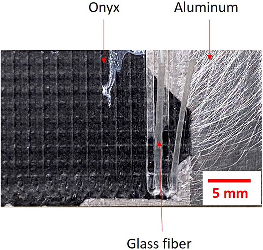
Inner face of the aluminum alloy of SCB sample after the testing.
Low-velocity impact test
The low-velocity impact tests were implemented in a drop mass tower and consisted of performing impacts with energy increments to characterize their dynamic performance. Table 3 shows the mass of the impactor used as well as the different impact energies evaluated for each material. The last impact energy values shown in Table 3, correspond to the perforation energy of the tested systems.
Low-velocity impact energies of the evaluated materials.
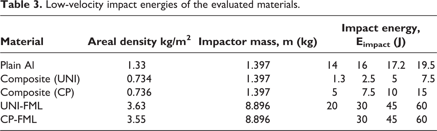
Figure 9a shows the force–time curves of the aluminum evaluated at different impact energies. The force–time curves of 14 J and 16 J correspond to the plastic deformation of the aluminum without producing further damage, whereas the 17.17 J curve corresponds to the initial cracking of the aluminum, observed as a sudden force drop. Finally, the curve of 19.52 J corresponds to the perforation of the aluminum with a typical localized petaling-like fracture which is shown in Figure 10a.
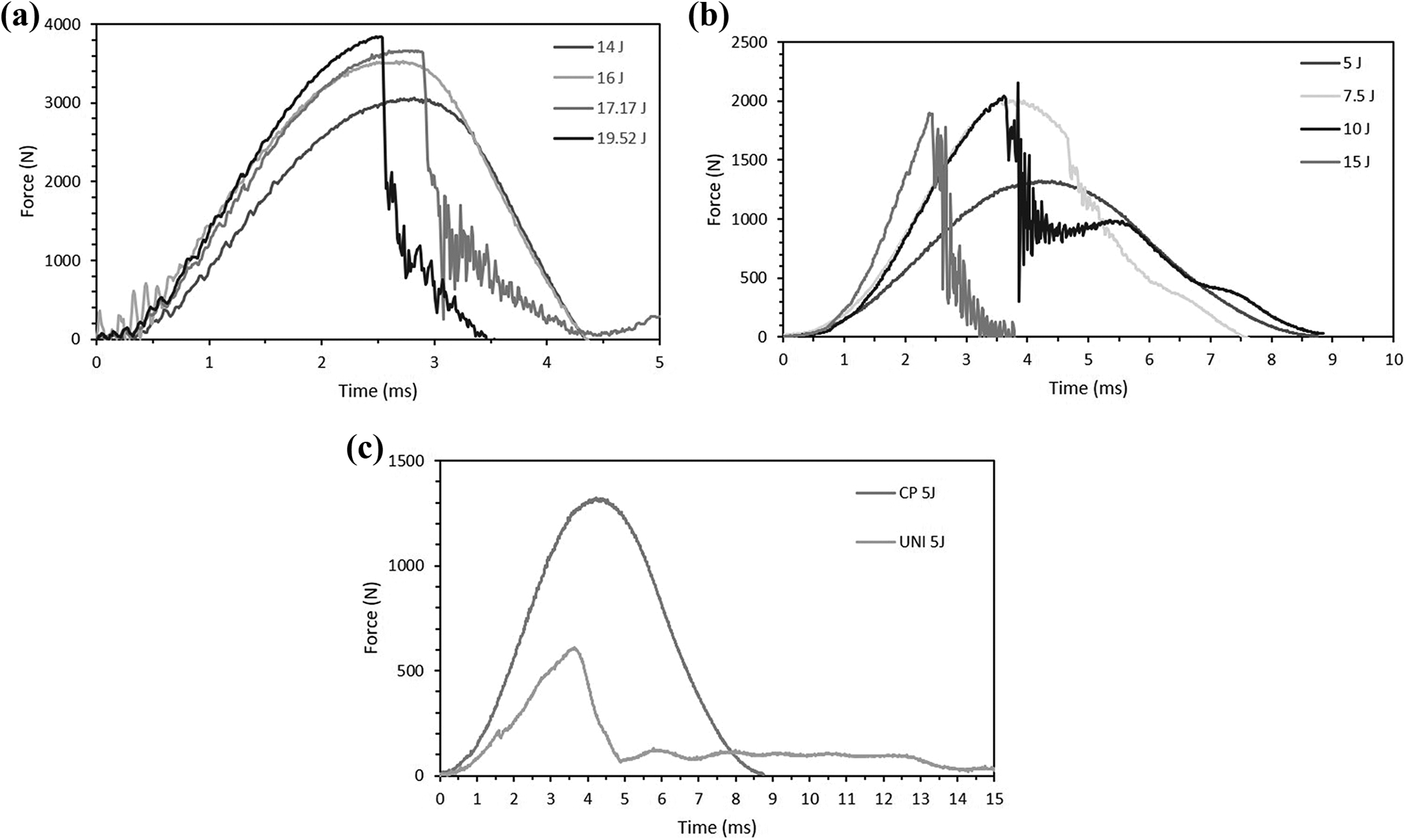
Force–time curves of FML constituent materials under different impact energies: (a) plain Al, (b) CP composite, (c) comparison of the CP and UNI composites under 5 J of impact energy.
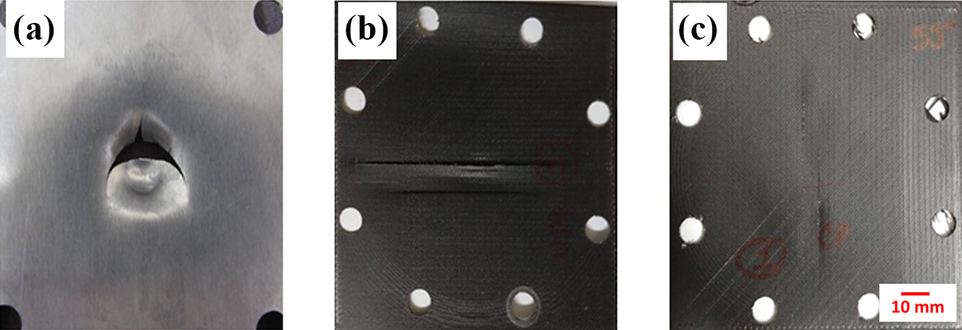
Fractured samples under low-velocity impact testing: (a) aluminum, (b) UNI composite, and (c) CP composite.
Figure 9b shows the force–time curves of the plain CP composite for each impact energy evaluated in which the curve of 5 J corresponds to the plastic deformation response. The curve of 7.5 J corresponds to the beginning of cracking of the composite, which was observed as the abrupt oscillation at 4.5 ms of the impact. The curve of 10 J corresponds to the cracking of the composite, whereas the curve of 15 J corresponds to the perforation threshold of this material. Similar results were observed on the plain UNI composite with the difference of a lower impact performance. In fact, Figure 9c shows the impact curves of the plain UNI and CP composites subjected to 5 J. It is observed that at these impact conditions, the UNI composites presented almost a full perforation, while the CP composite only showed plastic deformation. This performance appears to be related to the 0°/90° reinforcement offered by the CP arrangement, which helps blocking the entrance of the projectile more effectively. Figures 10b and 10c show the fracture profile of the UNI and CP composites under these perforation conditions, and the larger damage extent is obvious on the UNI sample displayed by the splitting fracture.
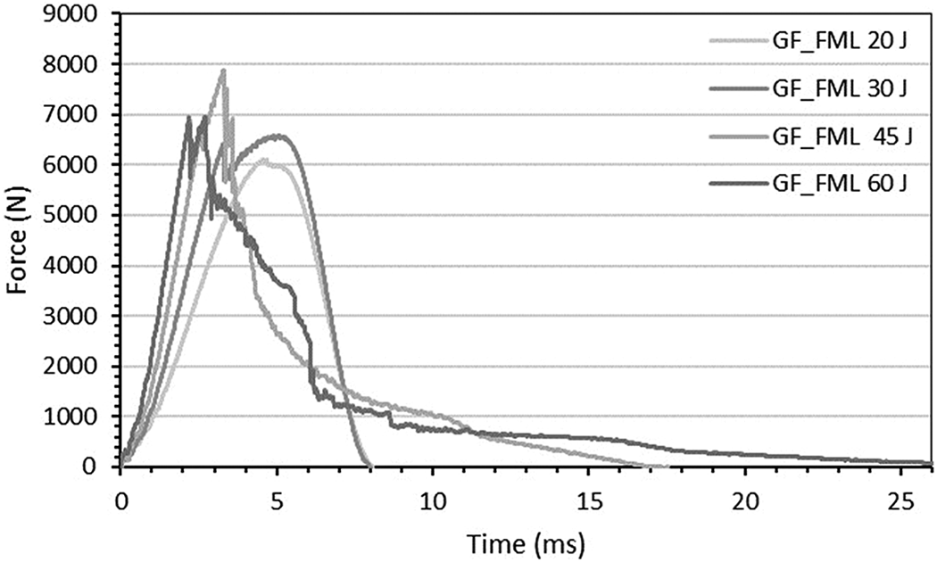
Figure 11 shows the force–time curves for the UNI-FML under each impact energy evaluated. The peak force for all curves resulted in higher values than the aluminum and the composites. The curve of 20 J corresponds to a plastic deformation response of the FML. At 30 J, a change in the impact behavior was observed with a sudden force drop related to the cracking of the aluminum layer in the non-impacted side (bottom). The force–time curve of 45 J shows the response of the FML in which the aluminum layer on the non-impacted and impacted sides were fractured. The remnant of force is attributed to the breaking of the composite core. Finally, the force–time of the 60 J impact corresponds to the perforation response of the FML. Similar impact profiles were observed on the CP-FML at the same energy range.
Low-velocity force–time impact curves of the UNI-FML.
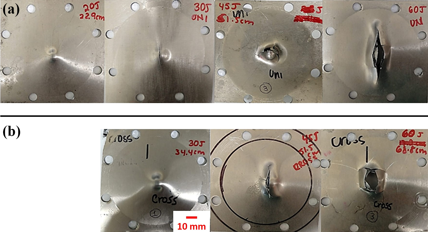
Figure 12 shows the fractured UNI and CP based FML after subjecting the samples to the low-velocity impact testing. The figure shows that at 30 J; rupture of the aluminum layer in the non-impacted side was observed in the UNI composite, whereas in the CP arrangement, only plastic deformation was observed. Differences are more obvious at 60 J where perforation on both systems was reached. For the UNI-FML, the rupture in the aluminum layer was produced parallel to composite fiber orientation,whereas on the CP-FML, this rupture had a 0°/90° petaling-like failure.
Fractured FML at different low-velocity impact levels of energies. (a) Unidirectional, (b) cross-ply.
Figure 13 shows a comparison of the impact energy levels to produce the different damages observed on each material. For the plain aluminum, the energy levels for plastic deformation, cracking and perforation energy are relatively close to one another. For the UNI composite, the gap between energy levels for the beginning of cracking and the perforation is small and perforation is exhibited at the same level of impact energy. The perforation of the CP composite reached 15 J, which indicates higher energy absorbing capacity, compared to the UNI composite. In the case of the FML, the gap from the plastic deformation response to the perforation is more significant than in the case of the plain aluminum; this difference may be attributed to crack propagation inter- and intralaminar, as well as debonding between the system layers involved in the FML, whereas in the aluminum there is only the crack propagation. Interestingly, the CP-FML and UNI-FML appear to yield a similar low-velocity impact performance. The CP arrangement under the low-velocity impact conditions did not provide a superior impact performance for the FML.
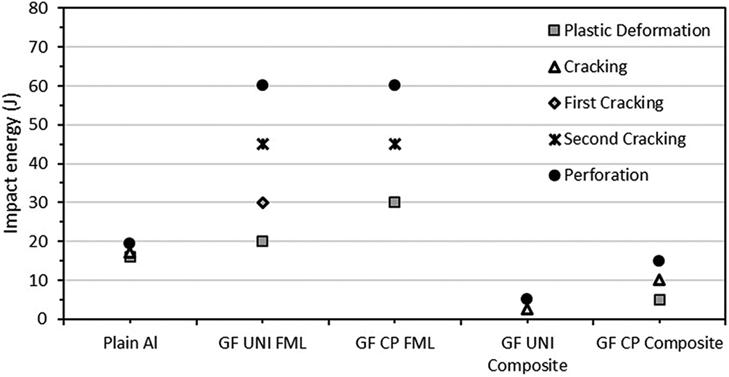
Summary of the low-velocity impact energies of FML and their constituent materials.
To fairly compare the impact performance of the FML and their constituent materials, the samples were normalized with respect to their areal density. Figure 14 shows the specific impact energy at the perforation threshold. From the figure, the FML yields a 9–13% superior specific impact performance than the plain aluminum alloy. The figure also shows the specific perforation energy of the UNI composite recorded at a lower value than the rest of the impacted samples. This lower value is due to the easy splitting fracture exhibited by the unidirectional arrangement. Figure 14 also shows that the largest specific impact perforation was recorded on the CP composite. This large perforation energy could be attributed to the membrane strain deformation which was the result of in-plane normal stresses that are constant over the thickness.39–41
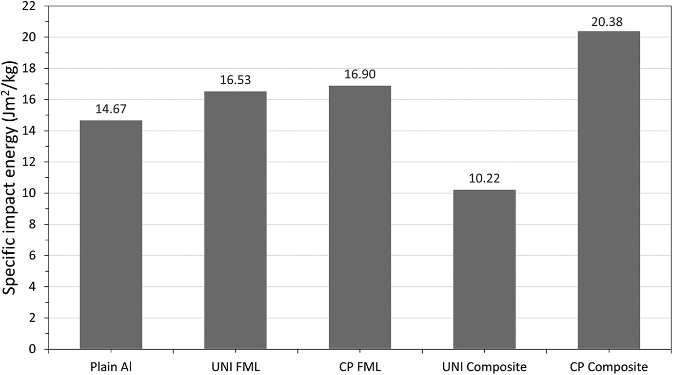
Specific impact energies for the FML and its constituent materials under low-velocity impact conditions.
High-velocity impact test
The high-velocity impact tests were conducted on a gas gun at different impact velocities. Figure 15 shows the perforation energy as well as the specific perforation energy of the investigated samples.
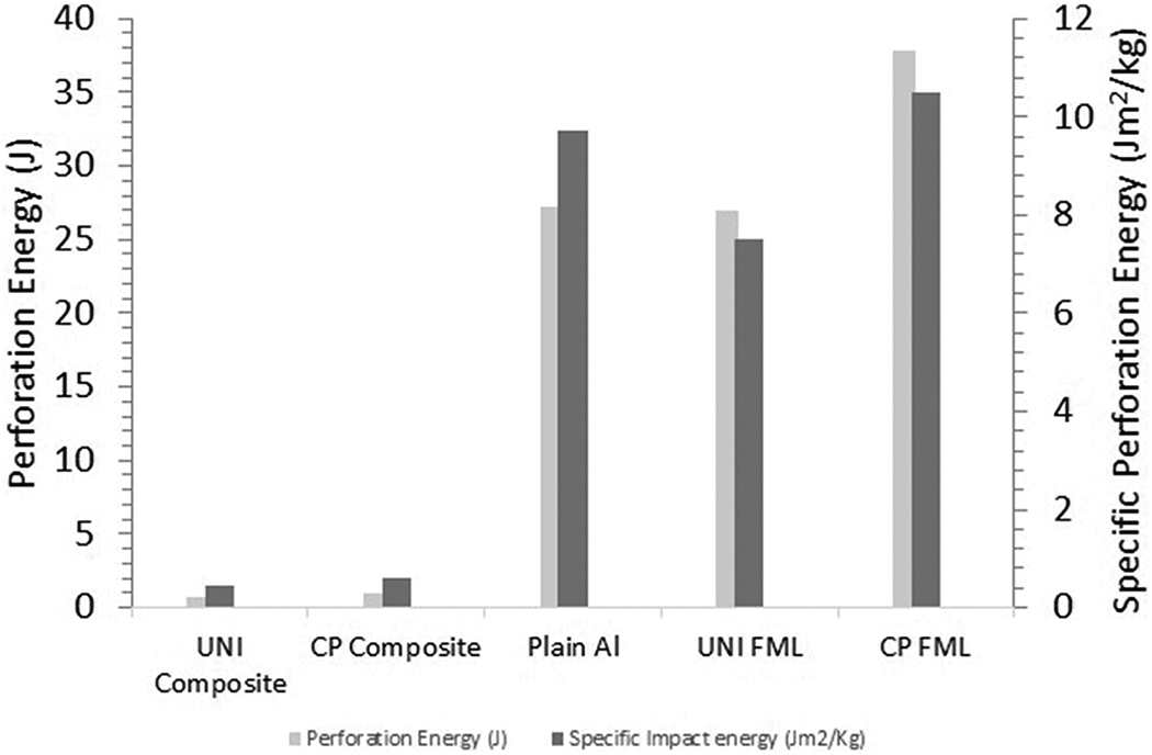
Perforation and specific perforation energies of tested materials under high-velocity impact conditions.
The figure shows that the perforation and specific perforation energies of the plain 3D printed composites resulted in values considerably lower than those shown by the FML and the plain aluminum alloy. It seems that the impacting projectile was able to easily perforate the ONYX-GF composite arrangement. This suggests that additional arrangements need to be investigated and implemented during the printing process of continuous reinforced composites. Scrocco et al. 42 indicated that the 45° configurational ONYX-fiber arrangement of printed parts strongly affects the impact performance of the composites. The figure shows that the plain aluminum yielded a superior impact performance than that of the plain composite materials, likely as a result of the membrane effect shown on thin metallic layers. 43 The figure also shows that the specific impact performance of the UNI-FML is lower than that recorded on the plain aluminum. The inclusion of the unidirectional composites increases the mass of the hybrid laminates without a substantial benefit in their dynamic response. Figure 15 also displays the perforation and specific perforation energies of the FML based on the CP arrangement, which appears to be the highest of the systems here investigated. This result, however, seems to be about 24% (38 J) lower than that reported by Abdullah and Cantwell. 44 Nonetheless, it is important to mention that they investigated a GF-FML manufactured by a traditional molding press system based on a 3/2 arrangement. Previous works on FML45,46 have shown that the impact performance of the 3/2 configurations is significantly higher than that displayed by 2/1 arrangements. Figure 16 shows the optical images of the perforated FML.
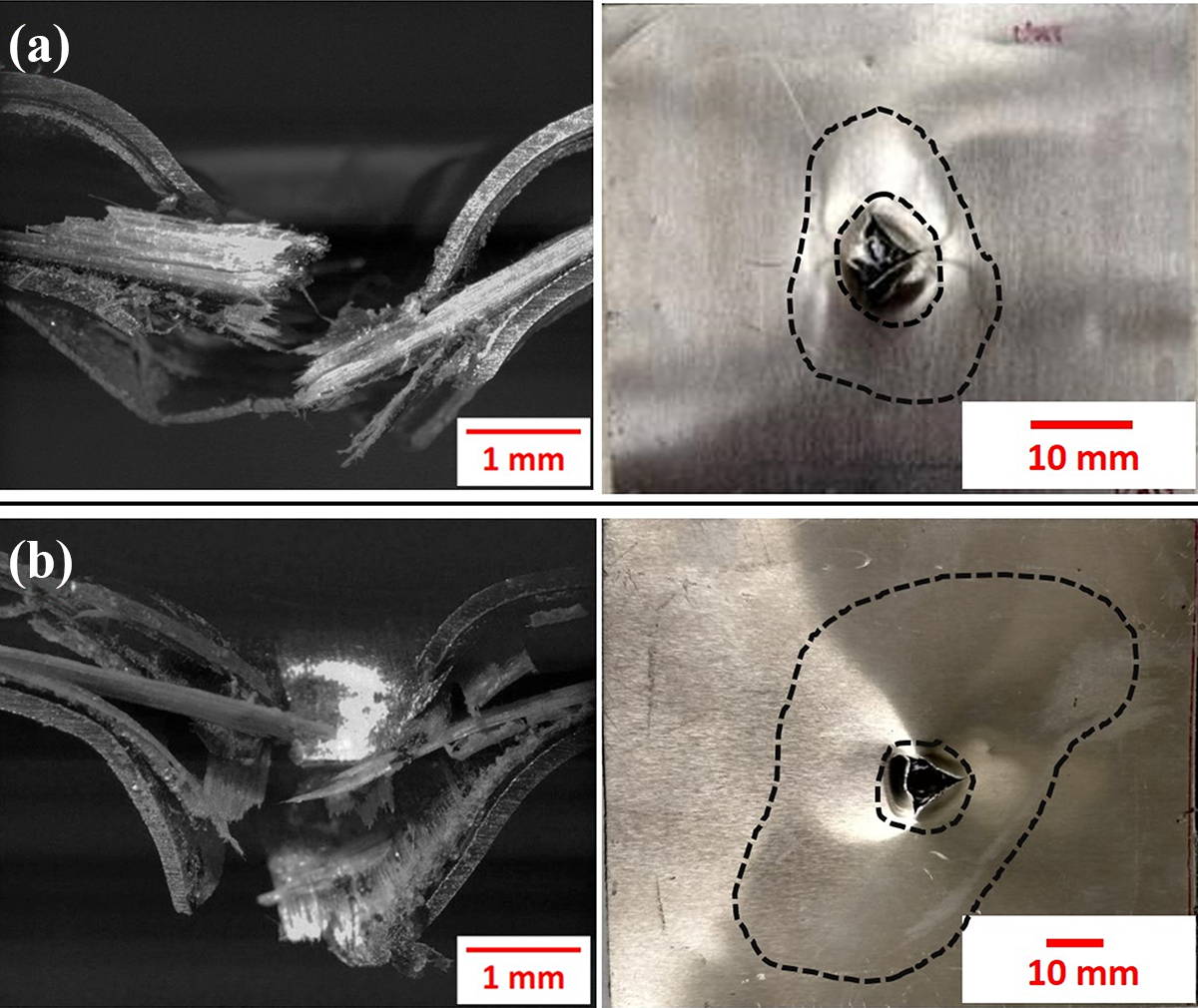
Optical images and rear impacted areas of the perforated FML under high-velocity impact conditions. (a) Unidirectional, (b) cross-ply.
The picture shows a typical petaling crack pattern on both UNI and CP-FML due to the perforation of the projectile. A closer inspection of the FML reveals that the CP-FML damage area is larger than that on the UNI-FML. The fracture analysis suggests that the superior fiber failure and laminar delamination shown on the CP-FML over the UNI-FML resulted in a higher impact absorbing capability as supported by the impact performance data shown in Figure 15.
Data comparison
Table 4 shows a comparison of the data reported on different GLARE systems investigated for the aerospace sector. It is observed that the FMLs manufactured in this work displays lower mechanical performance than those reported on the GLARE system. However, the purpose of the present research work was to provide the foundations to investigate the inclusion of 3D printing into hybrid laminates, rather than optimizing the mechanical performance of the investigated FMLs. Additionally, it is also worth noting that the studied laminates were based on a 2/1 configuration, which is different than the reported on the GLARE family, where the systems are typically based on a 3/2 and 4/3 arrangements. Current work by the authors is concentrating on producing their own reinforced filament on for fused deposition modeling. The results will be published in the near future.
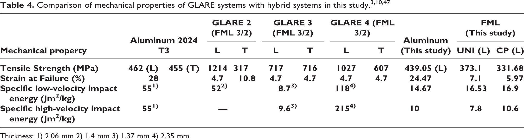
Thickness: 1) 2.06 mm 2) 1.4 mm 3) 1.37 mm 4) 2.35 mm.
Conclusions
From the tensile analysis, the tensile strength of the FML seems to fall between the strength of their constituent materials. The unidirectional composite presented only longitudinal splitting along the fibers direction due to the low strength provided by the thin 3D printed ONYX layer that maintains the composite compacted as a whole system. A further testing of the FML showed a delamination between the ONYX and glass fiber layers suggesting the need for a better printing process when manufacturing thin, fully reinforced composites in the Markforged system. The interfacial fracture toughness of the aluminum and printed composite was investigated, and the delamination occurred along the glass fiber-ONYX interphase, yielding a Gc value of about 1100 J/m2. The low-velocity impact tests showed that the CP-FML yielded the largest impact energies. Similar results were observed under high-velocity impact conditions. Optical analysis of the perforated FML showed that the fiber fracture, plastic deformation and interlaminar delamination are the main energy absorption mechanisms of the investigated FML under impact conditions. The present work has provided an initial research foundation on the fracture properties of a new kind of FML based on 3D printed composites. It is expected that this work can provide the foundations for considering additive manufacturing on the production of hybrid structures. The inclusion of 3D printed composites on FMLs could open the application of producing laminated systems with tailored properties on parts used in the transportation sector including the automotive, maritime, and aerospace.