
Abstract
Manufacturing of membranes for carbon dioxide (CO2) capture is a significant research topic. Achieving maximum CO2 sorption capacity while maintaining air permeability with a minimum number of technological steps was the main motivation of this work. The greatest advantages of this approach are its simplicity, low cost and easy transition to industrial scale. Electrospun nanofibrous membranes polyacrylonitrile (PAN)/triethylenetetramine (TETA) and polyacrylonitrile (PAN)/tetraethylenepentamine (TEPA) were prepared by one-step technology (modifying amines TETA, TEPA in different weight concentrations dissolved directly in spinning solution) using two different spinning conditions: needle spinning (electric field attached to a hollow needle through which a polymer solution is extruded under pressure) and wire spinning (electric field connected to a thin wire that is coated with a layer of polymer solution, and the spinning thus takes place from the free surface). Wire electrospinning turns out to be more suitable for a one-step technology with a modifying substance in the spinning solution. The best result as to the CO2 sorption capacity has been obtained for wire spinning PAN_TEPA_2% 11.7 ± 1.3 cm3/g with air permeability 53 ± 5 L/m2/s, which gives a good chance for the design of a sandwich functional unit for practical use. In addition to studies of CO2 adsorption, the article also deals with the comparison of both spinning methods for the PAN polymer, which have not yet been compared for this polymer in the literature, not only from the point of view of the possibility of preparing PAN nanofibers, but also their functional use precisely for CO2 capture.
Keywords
Introduction
In recent years, there has been increasing pressure to reduce the use of fossil fuels, mainly due to the increment of carbon dioxide (CO2) in the atmosphere, which is one of the so-called greenhouse gases responsible for global warming - a current and future environmental problem. Currently, the most common method (commercially) for CO2 capture is the use of aqueous amine solutions. Due to some disadvantages of amines, such as their corrosive nature and the need for extensive equipment new approaches are being sought and developed for CO2 separation that will facilitate production and reduce investment costs. Due to their unique properties, nanofibers are a suitable material for this purpose.1–3
Nanofibers, produced mainly by the most commercially used method - by electrospinning, have a unique porous structure, high specific surface area and good mechanical properties, thus showing the potential of advanced sorbents for CO2 capture and storage.4,5 In addition, the electrospinning technology provides the possibility of preparing chemically modified nanofiber membranes using the so-called one-step technology with the modifying agent dissolved directly in the spinning solution. Electrospun nanofiber materials are widely used as filtration media and their quality and efficiency depends mainly on fiber diameters, porosity and homogeneity as to the defect concentration like spheres, beads, islands, cotton wool etc.6,7 Fiber materials have recently been used mainly in connection with the covid-19 pandemic.8,9
Electrostatic spinning is a versatile method of producing ultrafine fibers mainly from polymer materials in the range from a few nanometers to a few micrometers by charging and extruding a polymer melt or solution through a spinning needle or from a free surface10–15 under a high-voltage electric field in the order of tens of kilovolts, solidifying it by gradually evaporating the solvent to form a fiber.16,17 Electrospun fibers can be formed in different morphologies, leading to their potential for use in various applications, such as oil-water separation, air filtration, food packaging and energy harvesting.18–23
The process of electrospinning and the resulting not only morphological properties are affected by a number of parameters, these are parameters of the spinning solution, such as conductivity, viscosity, surface tension, device parameters that we can set before the experiment - voltage on the electrodes, distance between the electrodes, feeding rate of the solution, speed of rotation or rewinding speed of the collecting electrode, etc. and environmental parameters, i.e. temperature and air humidity, which we can set if the equipment of the device allows it.24–30
The chemical treatment of nanofiber surfaces can be done either by a one-step technology with the modifying agent dissolved in the spinning solution, or by additional treatment that means the electrospun membrane is immersed in a solution of the modifying substance.31–34 Combinations of polymers (polymer nanofibers) and compounds with different functional groups, such as carboxyls, amines or thiols, allow their use as effective adsorbents for removing certain substances from air or aqueous solutions, such as dyes, acid gases or heavy metals. 35 Amines are known for their reversible reactions with CO2 molecules.2,31,35,36 The interaction of nitrile group (CN) containing polymer nanofibers (PAN) with amine functional groups (NH2) causes the formation of amine or amide (in an alkaline environment) groups on the surface of the fibers. By suitable addition of basic functional groups, such as amines, an increase in the sorption capacity for acidic compounds, such as acid gases CO2 and SO2 can be achieved.37,38
The connection of nanofibers and amines is not a new topic, nanofiber membranes as porous carriers of these substances have been used in a number of works, such as Wang et al., where they subsequently impregnated polyacrylonitrile (PAN) carbon nanofibers with TEPA amine to improve CO2 capture. 39 Zainab et al. 40 modified PU/PS composite nanofibers subsequently in a solution containing polyethyleneimine and triethylamine. CO2 sorption was also discussed by Jiao et al. 41 , who used silica particles as carriers of the amines diethylenetriamine (DETA), triethylenetetramine (TETA) and tetraethylenepentamine (TEPA). Ryanjanu et al. modified the PAN polymer with polyethyleneimine, which was applied by drop casting, to increase the hydrophilicity of the surface and use it to measure air humidity. 42 Song et al. 43 modified PAN by dipping in PEI solution with the addition of epichlorohydrin (membrane water resistance) to capture heavy metals from the water. The use of the above-mentioned amines is also abundant in the capture of heavy metals, with which they form stable complexes in water, such as lead (Youness et al. 44 ), silver and gold (Mahanta and Valiyaveett 45 ) or chromium, cadmium, copper and lead.46–48
In this work electrospun nanofiber membranes for CO2 capture based on polyacrylonitrile modified with various amines (triethylenetetramine - TETA, tetraethylenepentamine - TEPA) have been prepared. In contrast to the cited works performing chemical modification by the dipping electrospun membranes into the modifying solution, we used the one-step technology with modifying substances dissolved in the spinning solution. This technology is preferred by manufacturers of nanofibrous materials for its simplicity, low cost and easy transfer to an industrial production line. Furthermore, this work is devoted to the comparison of two basic electrospinning technologies: needle spinning and needleless spinning (i.e. electrospinning from a free liquid surface10–15) from the point of view of chemical modification of nanofibers. This difference in spinning technology proved to be significant for the preparation of chemically modified nanofibrous materials by one-step technology. Comparison of both technologies in terms of CO2 sorption capacity is presented and discussed. The prepared membranes are characterized by a number of analytical methods and the results of CO2 sorption capacity measurements are discussed in relation to the measured membrane characteristics and the used technologies.
Materials and technologies
PAN powder (purchased from Solvay company, with a molecular weight of 150 000 g·mol−1) was dissolved in N, N-dimethylformamide (DMF, purchased from Merck, Germany) by stirring for 24 h on magnetic stirrer at 50°C. The concentrations of PAN in the solution were 12 wt. % (wire spinning) and 7 wt. % (needle-based spinning).
These values of the used polymer concentrations in the solution were selected after prior optimization of the spinning process. For wire spinning there was no 7 wt. % concentration sufficient, on the contrary, for needle spinning the concentration of 12 wt. % was already too high in terms of the homogeneity of the spinning process and the resulting morphology of the textile. Therefore, these values for both technologies differ in the case of the devices we used.
Spinning solution parameters and labeling of samples.

In this work, wire (needleless – Elmarco company) and needle-based (Inocure company) electrospinning techniques were used and compared; A simple schematic of both techniques is shown in Figure 1. Schematic of electrospinning procedures for needle spinning and wire spinning used in this work.
Wire (needleless) electrospinning technique
Electrospinning process was performed on Nanospider laboratory device NS 1WS500U with wire spinning electrode (Elmarco company) – samples labelled as W_PAN_type of amine_weight concentration of amine. The wire electrode was made from steel with 0.2 mm diameter. The nanofibers were collected on the polypropylene (PP) nonwoven spunbond, which was moving around the collecting electrode with constant velocity of 30 mm/min. Spinning conditions were following: the distance between electrodes was 200 mm, the applied potential difference between spinning and collecting electrode was set to 70 kV, laboratory temperature 25°C and relative air humidity 25%. These parameters were chosen after previous optimization process. After the electrospinning process, the nanofibers were kept in air at room temperature.
Needle-based electrospinning technique
Needle-based electrospinning process was performed on Inospin laboratory device (Inocure company) – samples labelled as N_PAN_type of amine_weight concentration of amine. Used needle parameters were 1.26/0.90 (outer diameter/inner diameter in mm). The distance between electrodes was 111 mm, and the applied potential difference between spinning and collecting electrode was set to 50 kV. The nanofibers were collected on the polypropylene (PP) nonwoven spunbond situated on the collector surface, which was rotating with constant velocity of 500 rotations per minute. Spinning solution was forced through the capillary with feeding rate 0.15 mL/min. These experiments were carried out at laboratory temperature (25°C) and relative air humidity set to 45%. These parameters were chosen after previous optimization process. After the electrospinning process the nanofibers were kept on air at laboratory temperature. Table 1 summarizes all prepared samples and their labeling.
The parameter for the comparability of textiles prepared by both technologies was the area weight (area density), namely 5 g/m2, which was aimed to be achieved in the case of wire spinning by setting the rewinding speed of the substrate textile and in the case of needle spinning by the optimized amount of used polymer solution.
Samples were characterized using following methods: scanning electron microscopy (SEM and HRSEM) for morphology analysis, X – Ray Diffraction for assessment of crystal structure, infrared spectroscopy to control the presence of amines and chemical bonds PAN-amines, by measurements air permeability and CO2 sorption capacity.
Scanning electron microscopy (SEM) and High resolution SEM (HRSEM)
For
For
Fiji - image processing package49,50
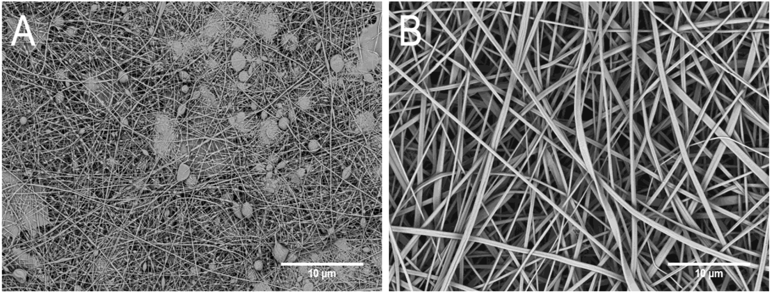
Fiji software allows the processing of images from scanning electron microscopy. It contains a number of plugins that can be used to obtain the required information from (SEM) images. For fiber diameter analysis, each image (primary magnification of 10kx, giving a pixel size of 28 nm), Figure 2(a)) was first converted to a binary image using various models, where the white fibers are on a black background (Figure 2(b)). The best segmented image was then subjected to fiber diameter analysis using this package, working with the entire image, which is an advantage over manual and lengthy measurements. The greatest accuracy was achieved by Huang’s fuzzy thresholding method. Below (see Figure 5), this analysis is compared with manual measurement of fiber diameters in the microscope software, both methods of diameter analysis are subject to a large measurement standard deviation due to the random arrangement of fibers during electrospinning. Segmentation using Fiji package of (a) SEM image to (b) segmented (binary) image for diameter analysis. SEM images (primary magnification 10 kx) - comparison of membrane structure for needle (electric field attached to a hollow needle through which a polymer solution is extruded under pressure) and wire (an electric field connected to a thin wire that is coated with a layer of polymer solution, and the spinning thus takes place from the free surface) technology of electrospinning for pristine PAN samples: (a) N_PAN_pristine - average fiber diameter 190 ± 70 nm (Fiji) and (b) W_PAN_pristine - average fiber diameter 280 ± 120 nm (Fiji).
X-Ray diffraction (XRD)
Structure and phase composition of nanofiber membranes were analyzed by X-ray diffraction analysis (XRD). PANalytical X'Pert PRO X-ray diffractometer in symmetrical Bragg-Brentano configuration under CuKα radiation (λ = 1.5418 Å) was used. Parallel X-ray mirror was located in the primary beam, and parallel plate collimator was located in the diffracted beam. Large Ni filter was located for Kβ suppression. Point sealed proportional detector was used. During the spinning process polymer fibers crystalize under specific conditions (strong electric field and humidity) and degree of crystallization is controlled by XRD analysis. XRD analysis is useful also for study crystalinity of additives, which may cause the defect formation.
Infrared (FTIR) spectroscopy
For the FTIR measurement Nicolet 6700 spectrometer was used. FTIR spectra were acquired using ATR sampling technique with a single reflection ZnSe crystal. The spectra of each sample were recorded in transmittance mode from 4000 to 650 cm−1, with a resolution of 4 cm−1 and 150 scans. Infrared spectra were graphically processed using Origin 2015 software.
Air permeability measurement
The air permeability was measured on a device designed from Polymertest (Otrokovice, Czech Republic). The measurement was carried out in accordance with the standardized procedure established by
Adsorption measurements
The measurement of the adsorption capacities of individual membranes was a key characteristic of this work, according to which the membranes were assessed and evaluated. The measurement was performed by CO2 adsorption/desorption isotherm. Samples were degassed at room temperature for 24 h. After that, adsorption and desorption isotherms were recorded with carbon dioxide using gas adsorption instrument (Autosorb iQ, Anton Paar, Austria). All samples were characterized three times with an experimental error of 5%. Maximum adsorbed amount of CO2 was calculated using the non-local density functional theory (NLDFT) model provided by Autosorb software. The values given by this measurement are in units [cm3/g], so it indicates what maximum volume of gas the membrane of a given weight can capture (by adsorption) - based on 1 G of membrane weight (relative to standard temperature and pressure (STP)). BET adsorption isotherm showing the CO2 adsorption and desorption process during the measurement as an example for one measured sample is in Figure 12. HRSEM images (primary magnification 50 kx) for samples: (a) N_PAN_TEPA_1% - average fiber diameter 202 ± 72 nm (Fiji), (b) W_PAN_TEPA_1% - average fiber diameter 290 ± 120 nm (Fiji), (c) N_PAN_TEPA_2% % - average fiber diameter 208 ± 85 nm (Fiji), and (d) W_PAN_TEPA_2% - average fiber diameter 400 ± 200 nm (Fiji).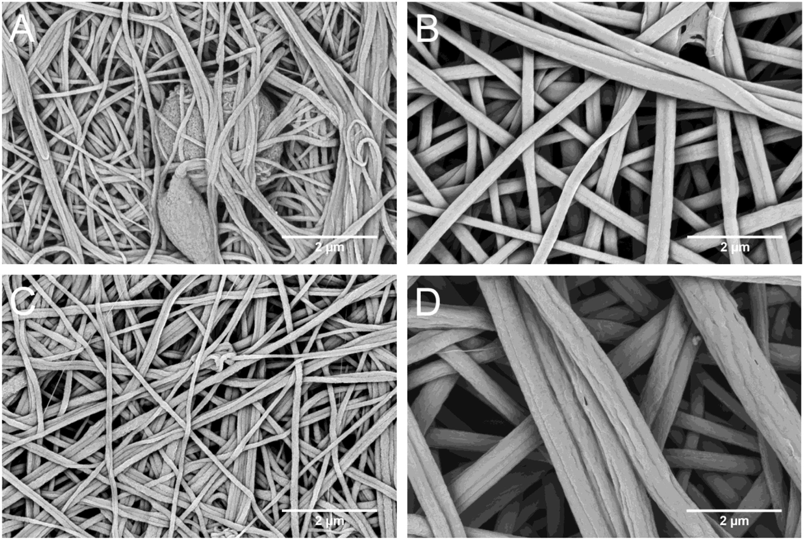
Results and discussion
Fiber morphology and membrane structure study
SEM analysis for pristine PAN membranes in the Figure 3 confirmed the difference in fiber morphology for both spinning technologies (needle and needleless) reported in literature (see for example10–15). Figure 3 illustrates the significant difference in membrane structure, where the membrane prepared by needle spinning showing a higher density (higher amount) of individual fibers in the layer with a higher concentration of defects. Defects appear in the membrane structure in the form of fused islands resulting in thin films, spheres, coils etc. Degree of fiber sticking increases with increasing concentration of both amines TETA and TEPA. As one can see comparing Tables 2 and 3 the fiber diameters are much smaller for needle spinning then for the spinning from the free surface (wire spinning) in both cases - pristine and amine modified fibers and also the dispersion of values is lower for needle spinning. PAN fibers prepared by wire spinning exhibit the flat tape structure, with a tendency to roll longitudinally forming hollow fibers as reported in.
52
This tendency is observable also for amine modified fibers at low concentration of modifying amine. Analysis of fiber diameters by measurement in electron microscope software to compare values with calculations in Fiji software - example for sample W_PAN_pristine. Fiber diameters, air permeability and sorption capacity for samples prepared by wire spinning. After exceeding the amine concentration 2 wt. % the samples were not spinnable by wire (W) spinning. The mean air permeability is based on a grammage (area weight) of 5 g/m2. Fiber diameters, air permeability and sorption capacity for samples prepared by needle (N) spinning. After exceeding the amine concentration 2 wt. % the humidity in the spinning chamber had to be increased to 60%, however the membranes were highly defective. The mean air permeability is based on a grammage (area weight) of 5 g/m2.


Figure 5 and 6 show the agreement of the software of the values measured by the Fiji software with the manual measurement of fiber diameters in the microscope, Figure 6 also provides information on the distribution of fiber diameters for the example sample W_PAN_pristine, where the most significant representation of fibers is in the range of 200–300 nm. Histogram of fiber diameter distribution from Fiji analysis, example for sample W_PAN_pristine (fiber diameter and frequency of diameters in the measured image).
Regarding the different concentration of defects in needle and wire spinning, the different effects of forces on the polymer jet in both spinning methods should be considered:
In needle spinning, the polymer material is extruded under pressure by a capillary, while wire spinning is spinning from a free surface. Another factor that affects the formation of defects is the higher voltage between the needle and the collecting electrode, which is made possible by our device and which enables a higher concentration of modifying substances in the fibers and also a higher yield of fibers during preparation. Since the needle electrode can be considered as a point and the rotating collector at a negative potential during spinning has a length of approximately 30 cm, there is an uneven distribution of the electric field, which also affects the experiment. A higher concentration of additives then leads to defects where the additives crystallize (see diffractogram – Figure 7). Another factor affecting the formation of defects is the humidity in the spinning chamber, which was optimized to the given value together with other parameters. XRD analysis (diffractograms) for samples: (a) N_PAN_TETA_2% (blue), (b) W_PAN_TETA_2% (red) compare to the pristine samples (black) from (a) needle and (b) wire technology.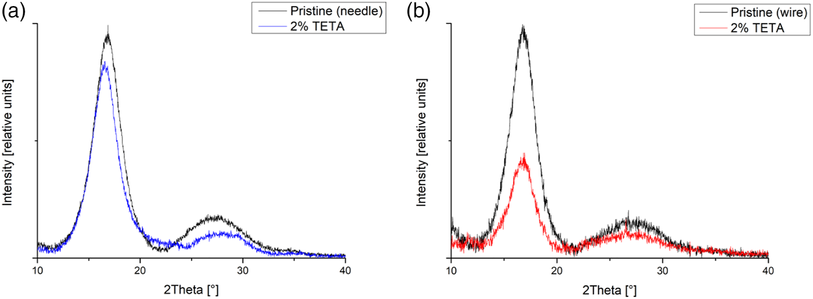
This work is primarily focused on the effect of technology on the chemical modification of nanofibers and their functionality. Wire and needle electrospinning with modifying amine in spinning solution showed significant differences between these two technologies. In the case of wire electrospinning, there is a concentration limit 2 wt. % of amine in the spinning solution. When this concentration limit was exceeded, isolated clumps of fibers are formed that do not form the continuous 2D structure desired for easy membrane design. Similar problems occurred using needle spinning. After exceeding the amine concentration 2 wt. %, the needle spinning process no longer proceeds stably and is not well reproducible. In order to maintain the stability of the spinning process and the fibrous nature of the membranes for higher amine concentration, it was necessary to increase the air humidity in the spinning chamber from the 45% up to 60%. Anyway the concentrations exceeding the 2 wt. % of amines led to highly defective structure with very low sorption capacity.
Comparison of membrane structure for amine-modified samples prepared by needle and wire spinning is in Figure 4 - HRSEM images for the samples: W_PAN_TEPA (wire spinning) and N_ PAN_TEPA (needle spinning) for two amine concentrations - 1 and 2 wt. % of TEPA. It is evident from the Figure 4 and Tables 2 and 3 that increasing amine concentration led to the increase of fiber diameters, which is more distinct for wire spinning. IR spectra for samples: (a) N_PAN_TETA_2% (red), W_PAN_TETA_2% (blue) and (b) N_PAN_TEPA_2% (red), W_PAN_TEPA_2% (blue) compare to the pristine samples (black).
Structure of PAN fibers has been monitored by XRD analysis. Figure 7 illustrates two characteristic examples of diffraction pattern for needle and wire spinning for samples N_PAN_TETA_2% and W_PAN_TETA_2%. In both samples prepared by needle and wire spinning, the polymer crystallized and degree of crystallization was not significantly affected by the presence of amines in the spinning solution. In electrospun fibers we did not observe the amorphous phase manifesting itself by the characteristic amorphous profile, but the profile broadening is clearly caused by small crystallites. Crystallites size depends not only on external spinning conditions, but also on the mutual interactions between polymer chains and modifying substance (see work 53 ).
Lower intensities for modified samples compared to pristine PAN samples are caused by the lower proportion of PAN in modified samples. Diffractograms show typical profile for electrospun samples affected by strong preferred orientation of polymer chains in fibers and fiber texture in 2D membranes. Peak profiles are very broad due to the small size of crystallites.
Amine bonding analysis
IR spectroscopy confirmed the chemical bonding between PAN and amines, as observed in
54
, what is extremely important for the stability of membranes composition. IR spectra are in the Figure 8, where it is clear that the C≡N bond is split into C=NH and C-NH as described in
54
- the reaction equation is in Figure 9. Whereas the C-NH bond is present in the spectrum due to the presence of amines in the sample - this bond is located directly in the amine. The C=N bond is created precisely as a result of the chemical bonding of the amine to the PAN chain after the division of the nitrile bond into these two newly formed bonds. While in the work
54
this bonding was achieved by subsequent amine-modification of electrospun membranes and then calcination at 120°C, in our experiment these bonds were created by one-step technology with amines in spinning solution, which represents a considerable technological and thus also economic simplification of the process of preparing a functional material, although partly at the expense of its capacity for the given application. SEM images (primary magnification 5 kx) of a sample N_PAN_TETA_5% prepared under a relative humidity in the chamber of (a) 45% and (b) 60% showing morphological differences.

Air permeability and sorption capacity measurements
Besides the sorption capacity, for the design of functional membranes, air permeability is an important parameter from a practical point of view and is affected by the mutual interaction of fibers, which is determined by their surface modification. In this case, the amines on the surface interact strongly as found by molecular modelling in our previous work.
55
The air permeability for wire spinning is many times higher than for needle spinning at the same values of sorption capacity (see Tables 2 and 3). For example, when comparing unmodified samples, an average air permeability value of 19.8 L/m2/s was measured for wire spinning, while only 3.17 L/m2/s for needle spinning. This different behavior of the membranes is due to the differences in the morphology and structure of the membranes for both technologies. Membranes prepared by needle spinning with a denser coverage of fibers in the layer after increasing the relative humidity in the needle spinning chamber membranes becomes more permeable as one can see in the Figure 10 comparing membranes N_PAN_TETA_5% for two different humidities: 45% and 60%. HRSEM images (primary magnification 100 kx) illustrating fiber bundles bonded by amines on the fiber surface for needle and wire spinning – samples: (a) N_PAN_TEPA_2% and (b) W_PAN_TEPA_2%.
Another important factor influencing the morphology and behavior of the membranes is the strong interaction of the fibers coated with amines, which leads to their sticking. These sticking of amine modified nanofibers has been observed and confirmed by molecular modeling in work.
55
Sticking the fibers together creates bundles and generally leads to higher air permeability of the membranes, as shown by the HRSEM image in Figure 11. This is caused probably due to the fact that, with the same density of fibers in the layer, by sticking the fibers together, larger pores are created between the individual bundles of fibers compared to the dense entanglement of individual fibers, which are not bonded without the presence of amine. However, since the spinning process is affected by countless different parameters, it can be caused by a combination of the influence of other parameters. BET adsorption isotherm showing the CO2 adsorption and desorption process during the measurement - example for sample W_PAN_TETA_2% (values related to standard temperature and pressure (STP)).
Measured CO2 sorption values for individual samples and both preparation technologies.
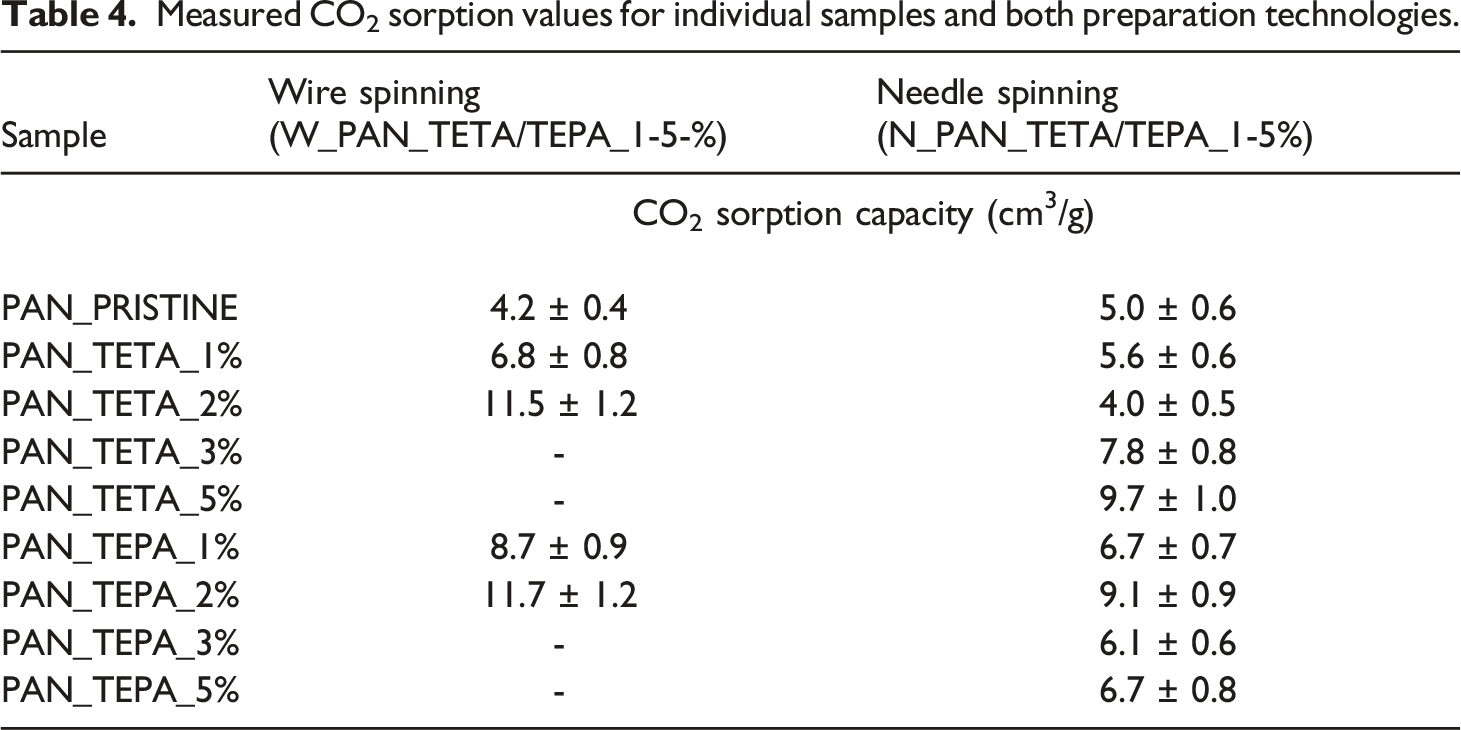
CO2 sorption capacity of membranes prepared by wire spinning increased with increasing the TETA and TEPA amine concentration up to the limit 2 wt.% in spinning solution, which is the limit concentration allowing a continuous spinning process and forming a continuous membrane layer. The highest CO2 sorption capacity in case of wire spinning has been obtained for W_PAN_TEPA_2%, 11.7 ± 1.3 cm3/g with the air permeability 48.3 ± 1.2 L/m2/s and for W_PAN_TETA_2%, 11.5 ± 1.2 cm3/g with the air permeability 53.0 ± 4.7 L/m2/s. Both amines exhibit nearly the same behavior as to the sorption capacity within the limits of measurement error.
In case of needle spinning the CO2 sorption capacity exhibits different concentration dependence for TETA and TEPA amine. Maximum CO2 sorption capacity has been achieved for N_PAN_TETA_5%, 9.7 ± 1.0 cm3/g with air permeability 68.5 ± 2.7 L/m2/s. For TEPA-modified samples, a maximum sorption capacity of 9.1 ± 0.9 cm3/g was observed for a lower concentration of amines than in the case of TETA (sample N_PAN_TEPA_2%), but at a very low air permeability. Comparing the results of both technologies, we can conclude that wire electrospinning turns out to be more suitable for a one-step technology with modifying substance in spinning solution.
As for stability, thanks to the chemical bond of the amine to the PAN chains, it is clear that the amines will not be released into the environment when applied to capture CO2, and the materials prepared in this way therefore show a high degree of stability. In addition, it turns out that for some samples after the desorption process, which took place spontaneously without changing the secondary conditions, similar values of sorption capacities were found by the subsequent measurement of the adsorption capacity, so these materials can be used repeatedly. However, only two measurements were made. The system was monitored for a gaseous medium consisting only of CO2, so it cannot be said whether it would be suitable for filtering CO2 from e.g. waste gas without other active parts of the filtration system.
Conclusions
This work was focused on the creation of electrospun nanofiber membrane chemically modified with TETA and TEPA amines for CO2 capture using minimum number of technological steps. With both technologies used (needle and wire) it was possible to prepare a nanofibrous textile from PAN, as well as to modify it with TETA and TEPA amines in one step under similar preparation conditions with different properties and therefore values for CO2 capture. Two key parameters were monitored in present work: CO2 sorption capacity and air permeability, which are significant from the point of view of the simple design of the functional unit for CO2 capture.
The highest values of CO2 sorption were achieved for wire spinning with modification 2 wt. % of TETA and TEPA amines with results of 11.5 and 11.7 cm3/g and for needle spinning with a modification of 2 wt. % amine TEPA with a result of 9.1 cm3/g and 5 wt. % by amine TETA with a result of 9.7 cm3/g, which corresponds to approximately two to three times the sorption capacity of pure PAN fabric. The values of sorption capacity in cm3/g achieved in this work are significantly lower than the published values for sorption materials in powder form because in one-step modification, part of the modifying substances is located inside the volume of the fibers and consequently not active. However, the membrane prepared in this work in the form of a 2D textile with good air permeability - in the case of wire spinning, 19.8 L/m2/s for the pristine and up to 53 L/m2/s for the amine modified sample will facilitate the design of a functional sandwich/cascade sorption unit and, moreover, with a minimum number of technological steps. With wire technology, we can quickly and easily prepare a large amount of functional nanofibrous material capable of capturing approx. 0.5 mmol/g of textile with the potential for industrial scale production.
Footnotes
Declaration of conflicting interests
The author(s) declared no potential conflicts of interest with respect to the research, authorship, and/or publication of this article.
Funding
The author(s) disclosed receipt of the following financial support for the research, authorship, and/or publication of this article: This work was supported by the Research Infrastructure NanoEnviCz, supported by the Ministry of Education, Youth and Sports of the Czech Republic under project NanoEnviCz (No. LM2018124). This work was also supported by the by the Technology Agency of the Czech Republic under the project Metamorph, project No. TO01000329, by the Czech Science Foundation [GAČR, no. 20-01639S], by SGS project (No. UJEP-SGS-2022-53-006-3), project ERDF/ESF “UniQSurf - Centre of biointerfaces and hybrid functional materials” (No. CZ.02.1.01/0.0/0.0/17_048/0007411, electron microscopy facility of IMIC, supported by the Czech Academy of Sciences (RVO CZ61388971).