
Abstract
Stable, reliable and high-speed weft insertion is an urgent challenge for high-speed industrial textile weaving devices. More stable and large electromagnetic forces can be provided by the segmented combined electromagnetic launch weft insertion, compared to the conventional electromagnetic launch weft insertion, which facilitates the realization of high-speed weft insertion. For digital electromagnetic launch weft insertion textile devices, it is necessary to respond quickly to the signals fed back by the sensors. Therefore, a fast and high-precision dynamical model capable of characterizing the kinematic properties of the weft inserter is extremely essential for control, which is conducive to the stable and reliable operation of the device. In this paper, we consider the electromagnetic force, weft yarn tension, air resistance, pipe wall friction, and gravity during the movement of the weft inserter, and establish a dynamic prediction model of segmented combined electromagnetic launch weft insertion (DPMSCEI) for control. Combining simulations and experiments to evaluate the performance of DPMSCEI validates the effectiveness and professionalism of DPMSCEI in solving electromagnetic weft insertion dynamics.
Keywords
Introduction
Super-wide industrial fabrics can be used in aerospace, 1 water conservancy and coastal defense,2,3 building environmental protection engineering 4 and other fields that require large-area industrial fabrics due to their integral molding. Compared with ordinary width fabrics, the integrally formed super-wide industrial fabrics have higher overall strength consistency and more stable performance when used in large areas. 5 The use of different functional materials for weaving allows super-wide industrial fabrics to have different characteristics and adapt to different domains. Super-wide industrial fabrics prepared by using superior-strength industrial yarn 6 is beneficial to strengthening the protection of dams, mountains and coasts, and reducing the damage caused by floods, typhoons and other disasters. The use of conductive yarns is beneficial to the preparation of large-area electronic smart skins 7 and large-area flexible sensors 8 in aerospace and other fields.
The difficulty in weaving super-wide industrial fabrics lies in the requirement that the loom can provide a sufficient weft insertion speed. For example, the loom with a spindle speed of 220 r/min is required to weave a fabric with a 12 m door width to achieve a weft insertion speed of 126 m/s. 5 At present, the weft insertion speeds of rapier looms, air-jet and water-jet looms, and projectile looms can reach 20 m/s, 66.67 m/s and 25.83 m/s, respectively. 9 The existing loom weft insertion method is difficult to achieve super-wide weft insertion. 5
With the rapid development of electromagnetic launch technology and pulse power control technology of electromagnetic launch system, 10 some researchers have seen the possibility of using electromagnetic force as power source to drive and complete weft insertion. In 1975, a patent for the first electromagnetic weft insertion scheme based on a conventional shuttle loom was proposed. 11 Since then, the electromagnetic weft insertion can be divided into two research directions from the perspective of the material used in the weft inserter. One is to use the permanent magnet as the carrier to drive the weft inserter to complete the weft insertion9,12 and the other is to use the high magnetic conductivity material as the carrier to complete the weft insertion based on the magnetoresistive electromagnetic launch principle. Since the demagnetization of the permanent magnet material weft inserter will affect the weft insertion performance during use, 13 we focus on the magnetoresistive electromagnetic launch weft insertion. The current research on magnetoresistive electromagnetic launch weft insertion can be divided into three aspects. The first aspect is to verify the feasibility of applying electromagnetic launch technology to weft insertion. 11 The second aspect is to study the influence of device structure parameters, 14 trigger position, excitation size and additional parameters on electromagnetic force.13,15 The single-stage 15 and multi-stage electromagnetic launch weft insertion 16 are configured with the exit velocity as the main evaluation index. The third aspect is to establish a surrogate model between the exit speed and additional parameters through machine learning and optimize the weft insertion performance through the surrogate model. Emad Owlia proposed an electromagnetic weft insertion system based on an adaptive neuro-fuzzy interface system, which is 26 times faster than the finite element analysis method. 17 The team then used genetic algorithms to optimize the model. 18
The above research lays a foundation for the application of electromagnetic launch weft insertion. The application of super-wide width electromagnetic launch weft insertion requires further improvements in the electromagnetic force of the weft inserter. However, the commonality of the above schemes is that, to facilitate the control of the coil power supply, the length of the acceleration coil and the weft inserter at each stage are designed to be consistent. A segmented combined electromagnetic launch weft insertion scheme is proposed to provide a more stable and larger electromagnetic force 19 which provides a specific solution for the super-wide width electromagnetic launch weft insertion.
For digital textile devices, it is necessary to respond quickly to signal feedback from sensors. Moreover, a control system requires further improvement to efficiently predict the position, attitude and velocity of the weft inserter during movement. The weft insertion speed control system of air-jet loom based on fuzzy logic is studied. 20 The control system of rapier loom based on fuzzy neural network and vector control optimization is studied.21,22 A fast, high-precision dynamic model that characterizes the motion characteristics of the electromagnetic launch weft inserter is critical for control. 23 The research on the weft insertion prediction model of super-wide width electromagnetic launch for control consists of three parts: prediction model theory, control model hardware and software development, and prediction model validation.
In the first part, the prediction model theory needs to consider as many external forces as possible in the weaving process to bring the model predictions closer to reality. Electromagnetic force plays a dominant role in electromagnetic launch weft insertion. An accurate model for the calculation of the electromagnetic force is extremely valuable for prediction model of electromagnetic launch weft insertion. Gradient magnetic fields are seen to be more suitable for analyzing electromagnetic forces. 24 Shaohua Guan focused on analyzing the influence of system parameters on the launch performance of electromagnetic induction coil launchers. 25 The electromagnetic force calculation model of magnetoresistive electromagnetic launch is widely used.26,27 Vangheluwe L proposed a numerical simulation model that can calculate the tension curve of weft yarn during weft insertion. 28 Traces of dynamic single cycle warp and weft tension for three looms used in the experimental programme are described. 29 Parker G W analyzed the relationship between air resistance and weft insertion speed during weft insertion. 30 On this basis, we considered the electromagnetic force, weft tension, air resistance, pipe wall friction and gravity of weft inserter in the weaving process, and established a dynamic prediction model of segmented combined electromagnetic launch weft insertion (DPMSCEI) for the prodction of super-wide width industrial fabrics.
In the second part, a suitable control model hardware and software platform facilitates the application of control model theory. A high-response hardware circuit with DC-DC regulation is designed to realize the control of the magnetic levitation sley for electromagnetic weft insertion. 31 A PLC control system is designed to control the electromagnetic weft insertion mechanism. 32 Combined the segmented combined electromagnetic launch weft insertion scheme, 19 we use STM32F103ZET6 as the controller to control the power on and off of the coils, construct the required gradient magnetic field, and realize the reciprocating electromagnetic launch weft insertion.
The third part is the validation of the prediction model. The wide application of the low-frequency electromagnetic field finite element analysis software MAXWELL33-35 provides convenience for us to quickly verify the performance of the model. MAXWELL is used and recognized in the field of electromagnetic launch weft insertion simulation. 36 We validate the performance of DPMSCEI using both simulations and experiments.
In this paper, we present the principle of super-wide width electromagnetic launch weft insertion, the working principle and the underlying calculation process of DPMSCEI. The performance of DPMSCEI is evaluated through simulations and experiments, and the effectiveness of DPMSCEI in solving the electromagnetic weft insertion dynamics is verified. DPMSCEI is able to determine the acceleration exit velocity and the parameter configuration of the acceleration device based on the user-defined loom spindle velocity and the width of the door width to implement the electromagnetic launch weft insertion. By adjusting the circuit parameters to control the electromagnetic force, DPMSCEI is beneficial to the dynamic feedback control of the high-speed loom. The built-in temperature rise algorithm can calculate the heat production of the device and facilitate the subsequent heat dissipation and reliability analysis of the device. After the application of segmented combined electromagnetic launch weft insertion technology in unidirectional weft insertion weaving is mature and stable, it can be developed towards multi-phase weft insertion looms 37 to further improve weft insertion reliability and fabric adaptability.
Super-wide width electromagnetic launch weft insertion
Figure 1 is a schematic diagram of the super-wide width electromagnetic launch weft insertion. The weft inserter reaches the target weft insertion speed under the action of the multi-stage energized coils and inserts the weft yarn through the shed formed by the warp. After the weft insertion is complete, the scissors at the ends of the fabric cut the weft yarn. Then the weft yarn is broken and rewinded. Finally, the weft inserter brakes and completes weft insertion. The weft transfer clamp transfers the weft yarn to the weft inserter. Under the action of the multi-stage energized coils, the weft inserter reaches the target weft insertion speed for the next weft insertion. The super-wide weft insertion is achieved by the reciprocal motion of weft inserter. Schematic diagram of the super-wide width electromagnetic launch weft insertion.
There are two technical key points: (i) How to achieve high-speed weft insertion? (ii) How to generate controllable weft insertion force?
Aiming at these two points, the principle of segmented combined electromagnetic launch weft insertion is used to accelerate the weft inserter. The DPMSCEI of weft inserter is established by analyzing the force of weft inserter in acceleration process and free flight process. The dynamic feedback control of the high-speed loom is achieved by tuning the circuit parameters to control the electromagnetic force.
Design goal of super-wide width electromagnetic launch weft insertion
The super-wide width electromagnetic launch weft insertion presented in this paper refers to the main parameters of the existing projectile loom. The maximum spindle speed
Principle of segmented combined electromagnetic launch weft insertion
A higher stability of the electromagnetic force can be provided by the segmented combined electromagnetic launch weft insertion compared to the conventional electromagnetic launch weft insertion, which facilitates the implementation to the realization of high-speed weft insertion. Figure 2(a) shows the variation trend of the electromagnetic force on the weft inserter when the weft inserter and a single energized coil are in different relative positions. According to the previous research, the force tendency of the magnetoresistive electromagnetic launch projectile is first accelerated and then decelerated, with a reverse pull occurring when the center of the projectile reaches the center of the coil. The principle of segmented combined electromagnetic launch weft insertion (a) The electromagnetic force distribution tendency of the weft inserter at different relative positions of the energized coil (b) The traditional electromagnetic launch weft insertion method (2 coils) and the segmented combined electromagnetic launch weft insertion method (12 coils) and electromagnetic force comparison.
The key point of segmented combined electromagnetic launch weft insertion is to divide a single energized coil into several energized coils and adopt a specific energization sequence, so that the weft inserter is constantly under the relative positions with larger electromagnetic force during the movement, as shown in Figure 2(b). This weft insertion method is beneficial for achieving fast and steady acceleration at short distances and in narrow spaces.
Dynamic prediction model of segmented combined electromagnetic launch weft insertion
The working principle of DPMSCEI can be divided into four parts, as shown in Figure 3. The first part is to determine the acceleration exit speed DPMSCEI calculation schematic diagram.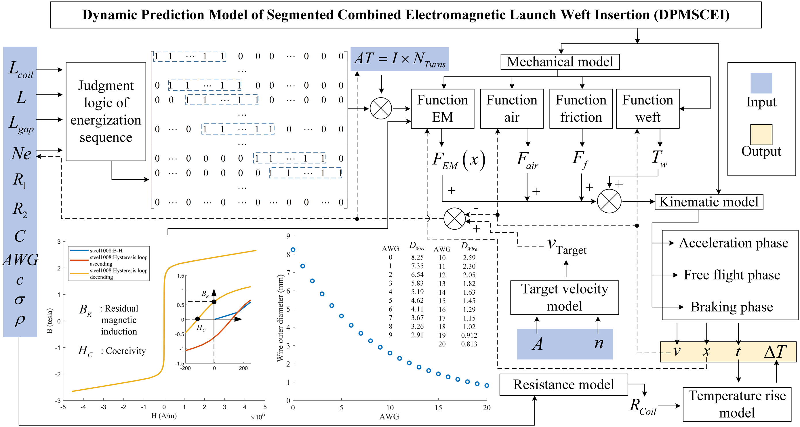
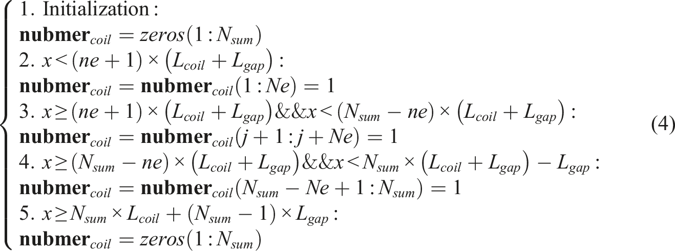
Judgment logic of energization sequence
The key to segmental combination is to construct a specific traveling wave gradient magnetic field according to the position of the weft inserter and changing the energization sequence of the coils, so that the electromagnetic force on the weft inserter remains near a larger value.
To determine the energization sequence of the coils, the system first needs to judge the number of energized coils each time and the relative position of the energized coils where the weft inserter is located. In this paper, the modified infrared sensor modules are used to detect the position of the weft inserter.
In practice, the length of the weft inserter 1. The total length of the energized coils and the air gap do not exceed the length of the weft inserter. 2. The number of energized coils is set to even. This setup is for the sensors to detect that the start terminal of the weft inserter is located at the center of the energized coils, so that the weft inserter is always subjected to a larger pulling force during the movement. The system determines the number of energized coils based on the following formula.


Number of energized coils:

According to the infrared sensor detection principle, the system determines the judgment logic of energization sequence under different sensor feedback signals based on the following formula.
For
Temperature rise model
The electromagnetic launch weft insertion we studied is based on the principle of magnetoresistive electromagnetic launch. In the system, mechanical, electrical, magnetic and thermal are coupled with each other. Wires of different wire gauges have different capacities for carrying current. Therefore, a more detailed modeling of the relationship between coil structure, resistance and wire gauge, coil turns arrangement can be used to evaluate the launch performance of electromagnetic transmission coils and the effect on temperature rise with different wire gauges and filling factors.
Structural parameters of electromagnetic launch weft insertion coil are listed as follows: coil inner radius
Coil cross-sectional area:

Wire diameter:

Wire cross-sectional area:

The average length of a wire circle:

Bare wire diameter:

Bare wire section:

Number of turns:

Ampere-turns:

Coil resistance:

According to Ohm’s law, the ohmic loss of the super-wide width electromagnetic launch weft insertion DC coil acceleration system can be expressed as follows.

The temperature rise of the coil can be expressed as follows.

Mechanical model
The weft inserter is mainly affected by electromagnetic force, air resistance, weft tension, pipe wall friction and gravity during its movement. The difficulty of DPMSCEI lies in the prediction of the electromagnetic force on the weft inserter under the mode of segmented combined electromagnetic launch weft insertion.
Electromagnetic force
Hypothesis: Using the idea of differentiation, the weft inserter is divided into multiple microsegments. The uniform magnetization is satisfied in each microsegment. The magnetic field intensity at the cross-section of each microsegment is uniformly distributed during the motion of the weft inserter. The distribution of the magnetic field at the axis can be used to characterize the distribution of the magnetic field at the cross-section. The magnetization time of the weft inserter and yokes are ignored. The effect of the magnetization history on the magnetization properties is ignored. Eddying effect, magnetic flux leakage and end effect are ignored.
We model the electromagnetic force in terms of the characteristics of the segmented and combined super-wide width electromagnetic launch weft insertion. Electromagnetic forces are the most prominent driving force in the weft inserter through electromagnetic launch, which directly affects the weft inserter performance of the loom. The sources of the magnetic field in the space are energized coils that perform switching according to a certain logic. The magnetic field excited by the energized coils in space magnetizes the yokes and weft inserter made of ferromagnetic material. Ferromagnetic materials can be divided into hard magnetic materials and soft magnetic materials. The design of electromagnetic launch weft inserter is bidirectional weft insertion, and the material of the weft inserter is soft magnetic material with low coercive force, low remanence and high magnetic permeability, as shown in Figure 3. According to the molecular current viewpoint in the magnetization theory, under the action of the torque of the magnetization field, the magnetic moments of the circulating molecules of each molecule are arranged along the direction of the field to a certain extent. Figure 4(g) shows the magnetizing current direction of the weft inserter. As shown in Figure 4(a), combined with Ampere’s force formula Mechanical and kinematic model analysis of weft inserter (a) Analysis of the calculation principle of electromagnetic force (b) The simplification of the weft inserter (c) Analysis of the calculation principle of electromagnetic force under the segmented combined electromagnetic launch method (d) The air resistance (e) The pipe wall friction (f) The weft tension (g) The forces of the weft inserter during acceleration phase (h) The forces of the weft inserter during free flight phase (i) The forces of the weft inserter during braking phase.
Magnetic flux continuity theorem: The net magnetic flux through any closed surface is equal to zero. Combined with Figure 4(c), there is

The electromagnetic force on any microsegment of the simplified weft inserter can be expressed as:

Where
After magnetization, the direction of the molecular magnetic moment

Under the above conditions, the magnitude of the magnetization current can be expressed as:
The magnetic field intensity and magnetic flux density at the axis of a single multilayer tightly wound solenoid coil
19
can be expressed as:


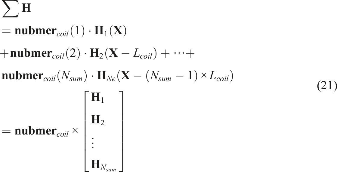
The magnetic field intensity of each microsegment when the weft inserter is in position can be expressed as:
Since we choose soft magnetic materials, we neglet the effect of the magnetization history, which is the hysteresis loop, on magnetization properties in the theoretical calculations and use the B-H curve for calculations. The magnetization of the material is expressed by the following formula.

Combined with the B-H curve of the material, as shown in Figure 3, the magnetization intensity and magnetic flux density of the weft inserter under different magnetic field intensities can be obtained. In this way, the magnetic flux gradients at the left and right ends of each microsegment can be resolved.
The electromagnetic force on the weft inserter can be further expressed as:

Air resistance
The weft inserter is affected by air resistance during its movement, as shown in Figure 4(d), (g)–(i). Referring to the resistance of the car during driving and the bullets flying, the air resistance suffered by the weft inserter can be expressed as:

Weft tension
The high weft insertion rate of the loom will cause yarn breakage, and the limit weft tension that different weft yarns can bear is different. For the high-speed weft insertion process, high-speed viscoelastic behavior of the yarn is particularly crucial.
The model of weft tension is:
28

The calculation result of the weft tension is around 1N.
28
In the model of this paper, we initially set the weft tension as
Pipe wall friction
During the acceleration process of the weft inserter, we need to design the air gap as small as possible to make the weft inserter receive greater electromagnetic force due to the characteristics of magnetoresistive electromagnetic launch. The existence of this design premise makes it possible to automatically adjust the position and attitude of the weft inserter in the magnetoresistive electromagnetic launch weft insertion, however the pipe wall friction will become one of the important forces that hinder the acceleration of the weft inserter. Since the radial air gap in the acceleration pipe is very small, it is assumed that the radial electromagnetic force on the weft inserter is not considered. Pipe wall friction, as shown in Figure 4(e), can be expressed as:
Considering that the weft insertion of the loom is a high-speed reciprocating motion, continuous work will increase the sliding friction coefficient between the weft inserter and the pipe wall. DPMSCEI can calculate the sliding friction coefficient between the weft inserter and the pipe wall in real time according to the speeds of the weft inserter detected by the sensors, combined with
Where
Gravity
During the 0.091s of weft insertion by the weft inserter, according to
Kinematic model
The movement process of the weft inserter is mainly divided into three phases: Acceleration, free flight and braking. The DPMSCEI we established can determine the exit speed that the weft inserter needs to achieve after acceleration according to the weft insertion requirements that the weft inserter needs to meet during the free flight stage. The configuration of parameters such as coil structure, number of coils and current excitation in the acceleration phase are then determined.
Acceleration phase
As shown in Figure 4(g), the weft inserter is mainly affected by electromagnetic force, air resistance, pipe wall friction, weft tension and gravity during the acceleration stage. Its motion process satisfies:

Free flight phase
As shown in Figure 4(h), the weft inserter is mainly affected by gravity, air resistance, and weft tension during the free flight stage. Its motion process satisfies:

Braking phase
As shown in Figure 4(i), the weft inserter is mainly affected by weft tension, air resistance, braking force and gravity during the braking stage. Its motion process satisfies:

We use the spring + sucker scheme to achieve weft inserter braking and energy recovery. The main principle is that the weft inserter relies on the spring for braking and energy recovery after the weft insertion is completed. The braking and energy recovery device converts the kinetic energy of the weft inserter into potential energy and then into kinetic energy while realizing the weft inserter reversing. The main function of the sucker is to provide time for weft handover.
The weft inserter will obtain an initial weft insertion speed after braking with the energy recovery device designed by us. DPMSCEI can also use the speed detected by the sensors as the initial value, combined with the current system structure parameter configuration, to predict the exit speed of the weft inserter under different current excitations. The current excitation that meets the target exit speed can be determined, which provides a theoretical basis for the dynamic feedback control of super-wide width electromagnetic launch weft insertion.
Super-wide width electromagnetic launch weft insertion scheme predicted by DPMSCEI
In this paper, aiming at the loom with the highest spindle speed of 220 r/min, the goal is to achieve the weft insertion with the maximum door width of 13 m.
The SIMULINK module in MATLAB R2018b is used to model and solve equation (24), equation (26) and equation (28) for the free flight phase of the weft inserter with the boundary condition of 0.091 s for the 13 m weft inserter motion described in Section Design goal of super-wide width electromagnetic launch weft insertion, as shown in Figure 5. Where Screenshot of SIMULINK model and solution interface in free flight phase.
The number of coils and the values of coils current excitation are configured according to the target exit velocity of the weft inserter calculated above. The SIMULINK module in MATLAB R2018b is used to solve the dynamical model of the weft inserter in the acceleration phase introduced in equations (16)–(26) and equation (27), as shown in Figure 6. Screenshot of SIMULINK model and solution interface in acceleration stage.
Super-wide width electromagnetic launch weft insertion scheme (width 13 m, loom spindle speed 220 r/min).
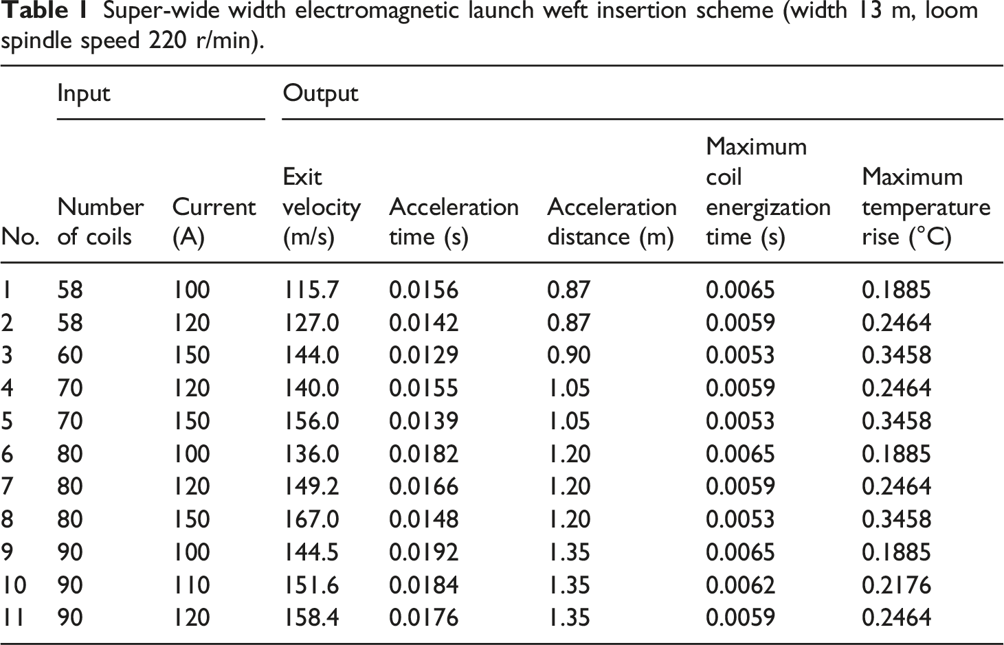
The configuration is based on the above structural parameters, the length of the weft inserter
Experiment
In order to verify the reliability of the DPMSCEI we have established, a corresponding finite element simulation model has been developed to compare and verify the feasibility of the super-wide width electromagnetic launch weft insertion scheme. For safety, a small segmented combined acceleration platform is built to verify the accuracy of DPMSCEI and simulation models at low power.
Finite element simulation
Ansoft Maxwell EM is a low-frequency electromagnetic field simulation software for industrial applications, which has significant advantages in calculating electromagnetic forces. We use the 2D transient solver in the cylindrical coordinate system in Maxwell2020 for analysis. The principle of calculation adopted by Maxwell for solving the electromagnetic force on the weft inserter is based on the following formula:
Equipment used: DESKTOP-455SV06
Processor: Intel(R) CPU E-52620 v4 2 2.10 GHz
RAM: 32.0 GB
Data in ds10.

Limitations: Consider that we use position-based timing of coil energization. As the speed of the weft inserter gradually increases, the real timing changes in the energized coils simulation are greatly affected by the analysis step size. A shorter analysis step can more sensitively judge the energization state of each coil, which is conducive to calculating a more accurate electromagnetic force. However, a shorter analysis step will greatly increase the amount of simulation data, and the model of segmented combined super-wide width electromagnetic launch weft inserter is very large. Such a setting will make it impossible for the computer we use to solve it.
Single stage electromagnetic force measurement
The key point of DPMSCEI is the accurate calculation of the electromagnetic force on the weft inserter. We need to focus on measuring and examining the electromagnetic forces, as shown in Figure 7(a)–(c). Experimental scene and principle (a) Single-stage electromagnetic force measuring device (b) Photo of relative position measurement between weft inserter and coil (c) Relative position measurement principle between weft inserter and coil (d) Segmented combined electromagnetic launch weft insertion experimental model (e) Single coil control loop (f) The principle of the weft inserter speed measurement.
Equipment used: American Huazhi PTT electronic analytical balance/0.001 g, WANPTEK-GPS3010 A power supply, coil, weft inserter, SR5100 diode, student scale/1 mm, bracket, and several wires.
Measuring principle of electromagnetic force: The weft inserter is placed on the American Huazhi PTT electronic analysis balance. According to
Measuring principle of distance: The Mi 12 mobile phone is used to shoot, and the shooting boundary is made parallel to the frame of the Huazhi PTT electronic analytical balance. Read the dimensions of the upper and lower ends of the coil and the lower end of the weft inserter in the photo that is flush with the scale. The length of the coil and the weft inserter are known, and the relative position between the weft inserter and the coil can be converted by using
Limitations: Only suitable for measuring electromagnetic forces smaller than the gravity of the weft inserter.
Weft inserter speed measurement
Weft insertion speed is an essential index to measure the weft insertion of super-wide width electromagnetic launch. We need to focus on the measurement and inspection of the weft inserter speed. Figure 7(d) shows the scene of the weft insertion experimental platform for segmented combined electromagnetic launch we built. The difficulty in constructing such a platform is to control the on and off states of all the coils according to the position of the weft inserter. Figure 7(e) shows the control circuit for a single coil, and the control circuit for multiple coils is an array of control circuits for a single coil.
The experimental platform of the electromagnetic weft insertion control part is mainly composed of an upper machine PC, a serial communication module, a single-chip microcomputer STM32F103ZET6, infrared sensor modules, drive circuit modules, control circuit modules, and electromagnetic coil modules. The upper machine communicates with the STM32F103ZET6 chip through the R232 serial port. The weft inserter triggers different infrared sensors. The single-chip microcomputer pin captures the corresponding signal and outputs high and low levels to a specific pin to control the on and off of the drive circuit modules, as shown in Figure 7(f).
Equipment used: STM32F103ZET6, infrared sensor modules
The principle of the weft inserter speed measurement: Infrared sensor module control pin outputs a high level when there is an object in the infrared sensor module and a low level otherwise. STM32F103ZET6 is used to capture the duration of the high level of the output terminal of the infrared sensor. Combined with the length of the weft inserter, the speed of the weft inserter can be calculated.
Results and discussion
Simulation results of segmented combined electromagnetic launch weft insertion scheme
Figure 8(a) and (b) are the results of sample of 10–100 and sample of 58–100 calculated by Maxwell, which is used to compare the performance of the traditional electromagnetic launch weft insertion method (sample of 10–100) and the segmented combined electromagnetic weft insertion method (sample of 58–100). The sample of 10–100 indicates 10-level coils, and the excitation for coils is 100 A. For sample of 10–100, each coil length is 84 mm. The number of turns is 900. The gap between adjacent coils is 3 mm. The total length of the sample of 10–100 is 840 mm. The sample of 58–100 indicates 58-level coils, and the excitation for coils is 100 A. For sample of 58–100, each coil length is 14 mm. The number of turns is 150. The gap between adjacent coils is 1 mm. The total length of the sample of 10–100 is 812 mm. The sample of 10–100 has a higher energy density input than a sample of 58–100. From Figure 8(a), it can be seen that the peak value and fluctuation of electromagnetic forces generated by the sample of 10–100 are larger than that of the sample of 58–100. The sample of 58–100 is more stable. The electromagnetic force with large fluctuations is more likely to produce fabric defects for weaving equipment. Combining with Figure 8(b), it can be observed that the input energy of the 58–100 sample is smaller, and the speed of the weft inserter after acceleration is larger. The segmented combined scheme is beneficial to improve the utilization rate of energy and improve the fabric quality at the same time. (a) The electromagnetic force of the weft inserter of sample of 10–100 and sample of 58–100 at different positions (b) The velocity of the weft inserter of sample of 10–100 and sample of 58–100 at different positions (c) The energization sequence of all coils in sample of 90–110 (d) The temperature rise of all coils in sample of 90–110 (e) The magnetic flux density at different time positions in the sample of 90–110 (f) The magnetic flux density gradient at different time positions in the sample of 90–110.
Since the segmented combined scheme currently uses infrared sensor modules for position detection, air gaps between the coils are required. Compared to the traditional electromagnetic weft insertion scheme, segmented combined scheme produces more magnetic flux leakage, which makes the peak electromagnetic force smaller than the traditional scheme. By using thinner infrared sensors to reduce the air gap between adjacent coils, the unit energy density of the acceleration device and the acceleration exit speed of weft inserter can be improved. Or using time-lapse artificial neural networks to predict the position of the projectile inside the coil instead of using infrared sensors. 40 Although the segmented combined scheme is weakened as the speed increases to improve the energy utilization rate, a more stable electromagnetic force is also a requirement for high-level textile equipment.
In order to more precisely analyze the characteristics of the segmented combined super-wide width weft insertion, we select the sample of 90–110 for analysis based on the weft insertion velocity requirements. Figure 8(c) is the energization sequence of 90 coils obtained by using the segmented combined control logic. It can be seen from Figure 8(c) that the energization time of the 6th coil is the longest. This is due to the fact that sample of 90–110 needs 6 coils to be energized each time, and the time taken to pass through post coils is reduced when the weft inserter is accelerated by the acceleration device. According to the segmented combined control logic of DPMSCEI, the serial number of the coil with the longest energization time is the calculated number of each energization. Figure 8(d) shows the temperature rise due to the heat generated by each coil after one acceleration calculated using equation (15). The temperature rise is mainly concentrated in the first 6 coils, with the 6th coil producing the largest amount of heat. Figure 8(e) shows the magnetic flux density at different times along the axis of the accelerator. Figure 8(f) shows the magnetic flux density gradient at different times along the axis of the accelerator. The red part in Figure 8(f) is the part where the gradient magnetic field is greater than 0, which is the position of the weft inserter during the movement. The electromagnetic force is positively correlated with the gradient magnetic field. The gradient magnetic field greater than 0 is conducive to generating positive electromagnetic force and promoting the acceleration of the weft inserter.
Figure 9 shows the magnetic induction line diagram and magnetic flux density cloud diagram of the model established by Maxwell at 2 ms, 14 ms, 18 ms, and 18.2 ms for samples of 90–110 respectively, and shows the position and speed of the weft inserter at these times. (a) The magnetic induction line diagram of the model at 2 ms for sample of 90–110 (b) The magnetic flux density cloud diagram of the model at 2 ms for sample of 90–110 (c) The magnetic induction line diagram of the model at 14 ms for sample of 90–110 (d) The magnetic flux density cloud diagram of the model at 14 ms for sample of 90–110 (e) The magnetic induction line diagram of the model at 18 ms for sample of 90–110 (f) The magnetic flux density cloud diagram of the model at 18 ms for sample of 90–110 (g) The magnetic induction line diagram of the model at 18.2 ms for the sample of 90–110 (h) The magnetic flux density cloud diagram of the model at 18.2 ms for the sample 90–110.
Electromagnetic force verification of super-wide width electromagnetic launch weft insertion scheme
Section Super-wide width electromagnetic launch weft insertion scheme predicted by DPMSCEI describes the super-wide width electromagnetic launch weft insertion scheme calculated using DPMSCEI (width 13 m, loom spindle speed 220 r/min). Considering safety, we use the professional low-frequency electromagnetic field commercial calculation software Maxwell to verify the super-wide width electromagnetic launch weft insertion scheme calculated by DPMSCEI.
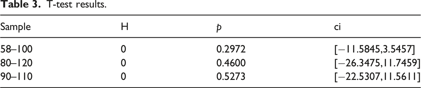
Figure 10(a) shows three sets of results of the electromagnetic force during the acceleration process of the weft inserter calculated using DPMSCEI and Maxwell. Figure 10(b) shows the relative error calculated using the two methods. The relative error between the two methods in the initial state is 14%, which is mainly due to the fact that DPMSCEI ignores the end effect. The relative error is stable within −4% as the main magnetic flux of the coil has a much larger effect on the weft inserter than the end effect after the weft inserter enters the coil. (a) Three sets of results of electromagnetic force in the acceleration process of weft inserter calculated by DPMSCEI and Maxwell (b) Relative error of electromagnetic force in the acceleration process of weft inserter calculated by DPMSCEI and Maxwell.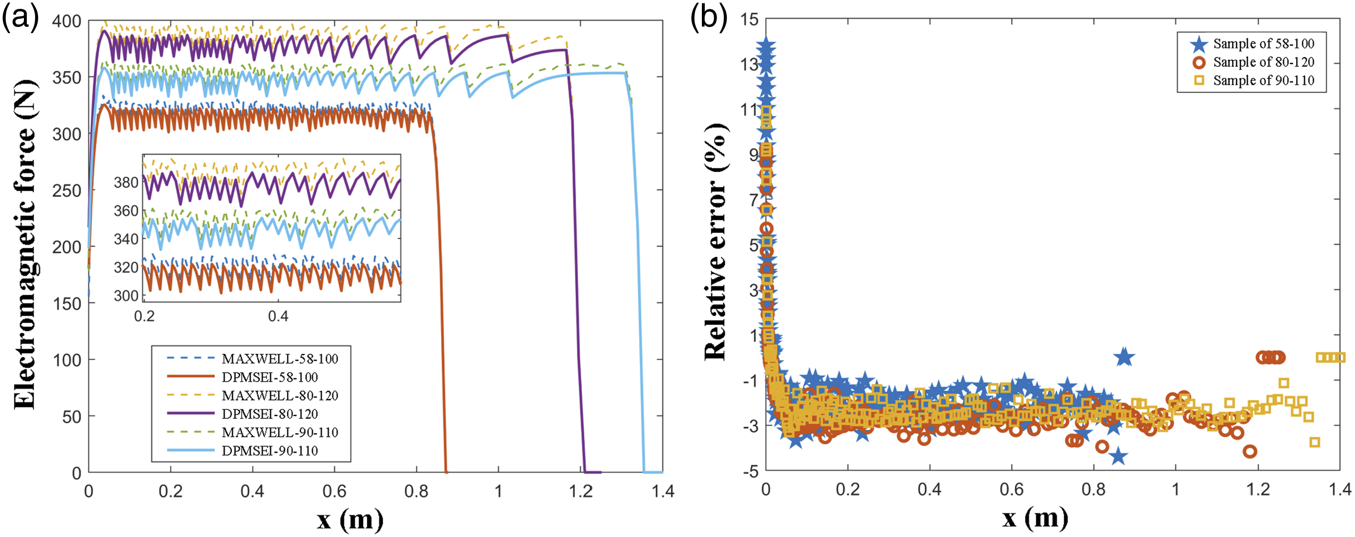
T-test results.
Comparison of DPMSCEI and Maxwell running speed.

Electromagnetic force verification
Model data: The length of the weft inserter is 101 mm, the diameter of the weft inserter is 8 mm, the inner diameter of the coil is 14 mm, the outer diameter of the coil is 30 mm, the length of the coil is 90 mm, the number of turns is 250, and the constant current source is 1.5 A.
Figure 11(a) shows the electromagnetic force of the weft inserter and the accelerating coil at different relative positions using Maxwell and actual measurement. Figure 11(b) shows the relative error of Maxwell and actual measurement results. (a) The electromagnetic force of the weft inserter and the accelerating coil at different relative positions obtained by using Maxwell and actual measurement (b) The relative error of the electromagnetic force calculated by Maxwell and actual measurement results.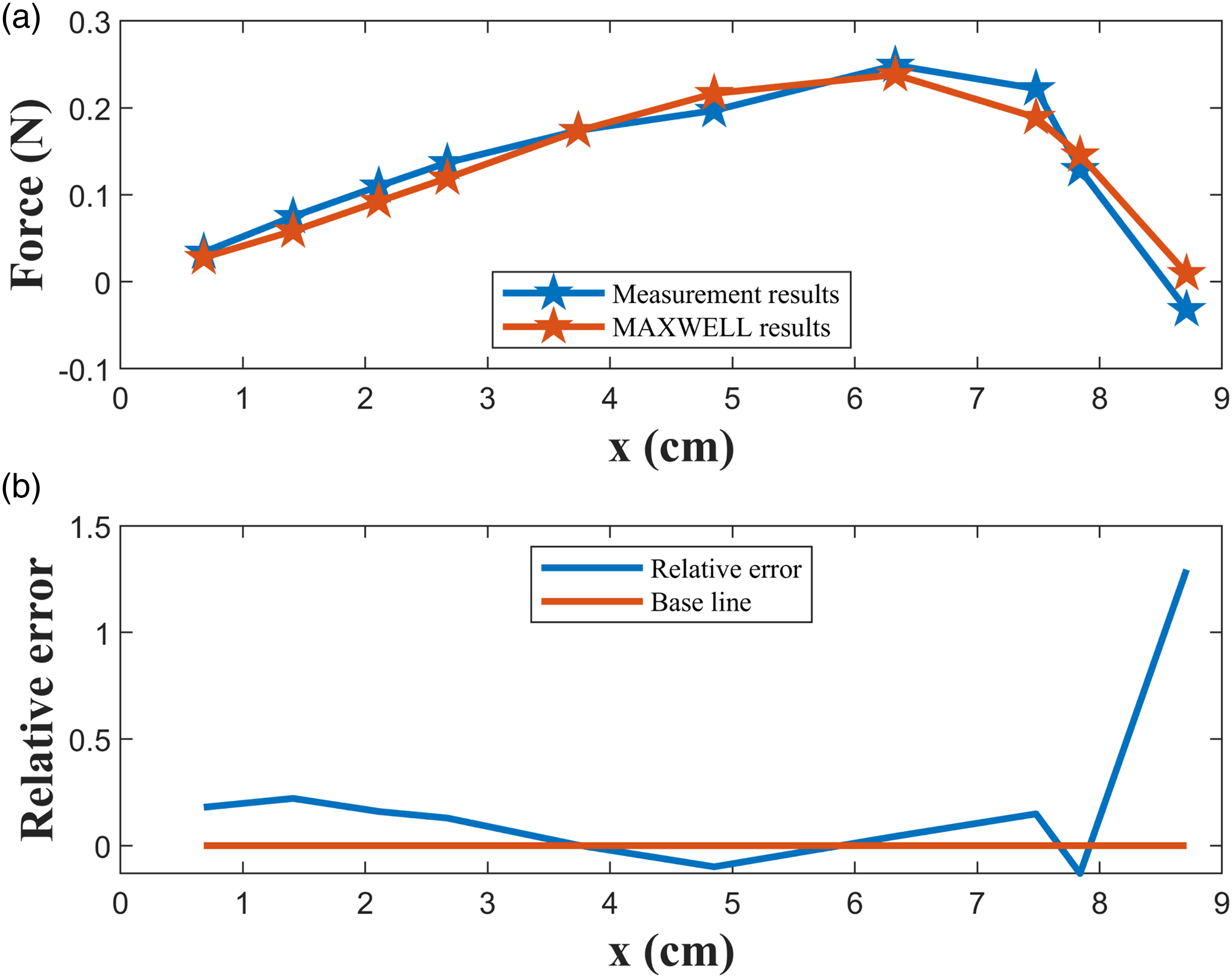
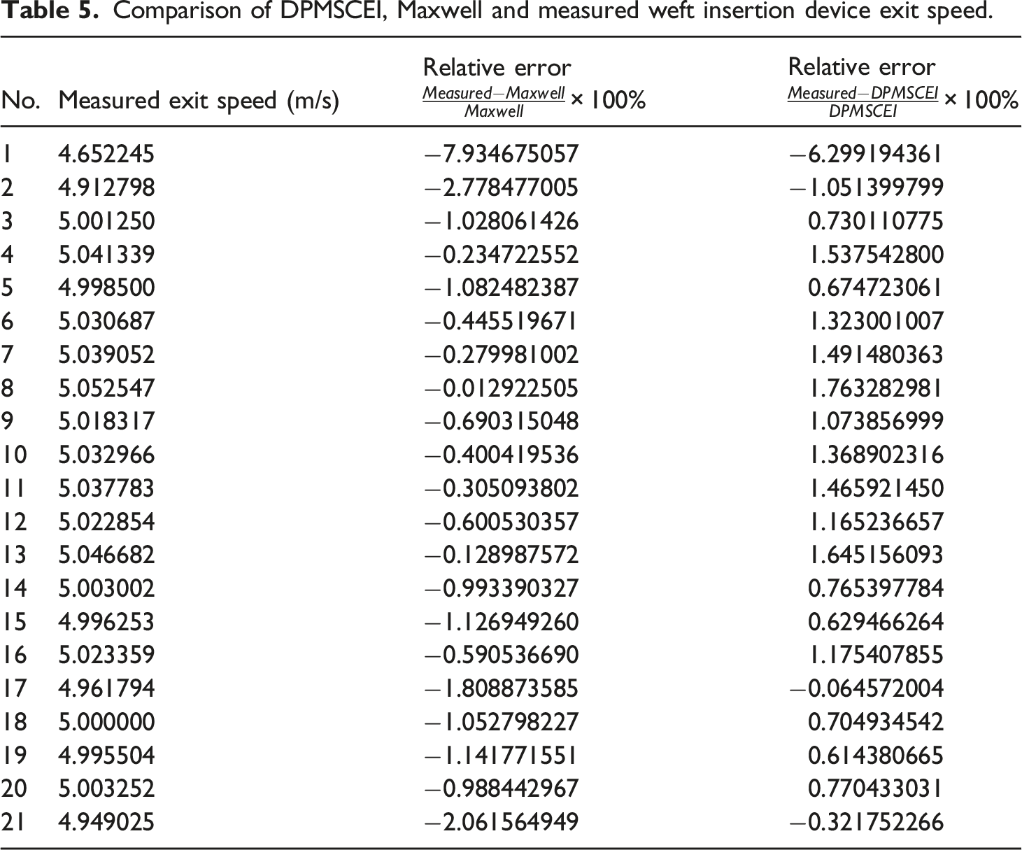
Speed verification of DPMSCEI at low power
Model data: Yoke thickness is 0.2 mm, weft inserter length is 101 mm, weft inserter diameter is 8 mm, PV pipe inner diameter is 14 mm, total acceleration zone length is 210 mm, coil inner diameter is 14.5 mm, outer diameter is 20 mm, single coil length is 13 mm, resistance is 5.6
Comparison of DPMSCEI, Maxwell and measured weft insertion device exit speed.
Conclusion
A higher stability of the electromagnetic force can be provided by the segmented combined electromagnetic launch weft insertion, which is beneficial to the super-wide width weft insertion.
In contrast to the model established by the electromagnetic field simulation software MAXWELL, DPMSCEI is able to take into account factors such as gravity, weft yarn tension, air resistance, and pipe wall friction on the weft inserter during the weft insertion process, which is conducive to establishing a more complete weft insertion power control model. DPMSCEI has faster response speed and high prediction accuracy. Compared to MAXWELL, the response speed can be increased by up to 8000%, and the prediction accuracy for the relative error of the electromagnetic force is stable within −4%. The relative error with respect to the measured value is within 2% compared to the speed during the acceleration process predicted by DPMSCEI. DPMSCEI can control the magnitude of the electromagnetic force by adjusting circuit parameters, which is beneficial to the dynamic feedback control of high-speed looms.
Footnotes
Declaration of conflicting interests
The authors declared no potential conflicts of interest with respect to the research, authorship and/or publication of this article.
Funding
The author(s) disclosed receipt of the following financial support for the research, authorship, and/or publication of this article: This work was supported by the National Natural Science Foundation of China (Grant No. 51541503, 50775165, 51775389), Hubei Key Laboratory of Digital Textile Equipment (Grant No. DTL2022027), State Key Laboratory of New Textile Materials and Advanced Processing Technologies (Grant No. FZ2020008) and China Scholarship Council (Student ID: 202210810002).