
Abstract
Two-scale modeling is adopted to investigate the thermo-mechanical behavior of 3D four-directional (3D4D), 3D five-directional (3D5D), and 3D full five-directional (3DF5D) braided composites. Based on the stress-strain relationship considering thermal expansion and the periodic boundary conditions, the elastic constants and the coefficients of thermal expansion (CTE) of the three types of braided composites are predicted by a two-scale homogenization method. The micro stress under free expansion and thermo-mechanical coupling is also simulated. The calculated results are in good agreement with experimental results from relevant references. The numerical results show that the longitudinal elastic and thermal expansion properties are gradually improved with the increase of axial yarn content from 3D4D to 3D5D and then to 3DF5D braided composites. The braiding angle corresponding to the zero longitudinal CTE of each braided structure is basically about 40°. Furthermore, with the increase of temperature, the longitudinal micro-stress in yarns increases gradually, but that in matrix drops. These conclusions will provide a reliable basis for the structural optimization design and safety evaluation of 3D multi-directional braided composites in a thermal environment.
Keywords
Introduction
Due to the interlocking structures of the reinforced phase, three-dimensional (3D) braided composites have high damage tolerance and excellent ability to resist impact and fatigue loads.11,2 Furthermore, they have good designability and can be fabricated into various multi-directional and complex-shaped structures.3–6 Therefore, 3D braided composites have been widely used in aerospace, aviation, new energy and other high-tech fields, and their mechanical properties analysis and structural design have become the research focus at present.
Generally, representative volume element (RVE) models were established to investigate the properties of composites according to their structural periodicity. The heterogeneity of 3D braided composites is mainly reflected in the micro and meso scale, as shown in Figure 1. On the meso scale, 3D braided composites are composed of reinforced long fiber bundles (also called yarns) and matrix, and can be divided into mesoscopic unit cells as shown in Figure 1(b). Lots of unit cell models were proposed by analyzing the microstructure of 3D multi-directional composites, such as the “four straight yarns model”,
7
“helix geometry model”,
8
“triple unit cell model”
9
and “multi-unit cell model”.
10
Meanwhile, on the micro-scale, a yarn consists of thousands of fiber filaments and bonded matrix. According to the periodic arrangement of the fibers in a yarn, microscopic RVE can be established, as shown in Figure 1(d). In some articles, kinds of microscopic RVE models were proposed to predict the mechanical properties of the yarn.11,12 In recent years, considering the heterogeneity of yarns and braided structures, the elastic or linear viscoelastic properties of complex textile structures were predicted by using a bottom-up homogenization method.13–15 Multi-scale structures of 3D braided composites (a) 3D braided preform (b) Mesoscopic unit cell (c) Yarn (d) Microscopic RVE.
Early research on 3D multi-directional braided composites mainly focused on the prediction of their equivalent elastic properties.16–21 To make the composites safely applied in primary load-bearing structures, the micro-stress and the progressive damage simulation have become important and challenging topics for the strength analysis of 3D braided composites. Kang et al. 22 and Song et al. 23 adopted real-time online damage monitoring methods to investigate the static and fatigue failure propagation of advanced 3D textile composites through a three-point bending test. Zeng et al. 24 established a multiphase element model for calculating the local stress of 3D braided composites. Fang et al. 25 simulated the microscopic damage behavior of 3D braided composites by means of Murakami’s damage theory and finite element method. Dong et al. 26 and Zhai et al. 27 simulated the progressive damage of 3D braided composites by the asymptotic expansion homogenization (AEH) method. Zhang et al. 28 established a damage-friction combination interface constitutive model to predict the stiffness and strength properties of 3D braided composites. Pei et al.29,30 investigated the effect of damage on the modal properties of 3D braided composites by means of experimental and finite element methods. Najjar et al. 31 developed an optimized artificial intelligence model to predict the kerf quality characteristics in laser cutting of basalt fibers reinforced polymer composites. Sadoun et al. 32 investigated the effect of through-the-thickness position of aluminum wire mesh on the mechanical properties of GFRP/Al hybrid composites. Fathy et al.33–35 fabricated nano-particle reinforced composites and studied the effects of nanoparticles on their mechanical properties.
In order to meet the requirement of applications in thermal environment, much attention has been paid to the thermo-mechanical behavior of 3D braided composites. There are mainly two aspects of research: one is the prediction of thermophysical properties, the other is mechanical analysis under thermal environment. Among thermophysical parameters, the coefficient of thermal expansion (CTE) is the main parameter that affects the thermal stability of the structure. Considering the effects of temperature and braiding parameters, some experiments were conducted to test the CTE of 3D braided composites.36–38 For numerical prediction, Lu and Xia39–41 used finite element methods (FEM) based on periodic boundary conditions to predict the CTE of 3D four-directional (3D4D), 3D five-directional (3D5D) and 3D full five-directional (3DF5D) braided composites. Guo et al. 42 used an improved genetic algorithm to optimize the zero-expansion design of 3D n-directional braided composites. Pottigar et al. 43 presented 3D braided composites with zero, negative and isotropic CTE based on an analytical homogenization technique. Zhai et al.44,45 presented a modified AEH method to predict the thermal conduction and thermal expansion properties of 3D braided composites.
Although lots of achievements have been made on the CTE of 3D braided composites, there are relatively few investigations on the micro-stress and strength analysis in thermal environment. Jiang et al. 46 presented a multiphase finite element model to simulate the micro-stress of 3D braided composites. Wang et al. 47 proposed two models of microstructure and multi-unit cells to investigate the interfacial thermal stress of 3D braided composites. Fu et al. 48 simulated cure deformations and residual stresses of 3D braided composites based on the thermochemical and thermodynamic models. For experimental research of strength, Jiang et al. 49 experimentally studied the tensile and compression properties and failure mechanism of 3D4D braided composites under thermal environment. Li and Zuo3,50 conducted compressive strength tests on 3D5D and 3D seven-directional (3D7D) braided composites at different temperatures. Li et al. 51 established a temperature-dependent progressive damage model to analyze the off-axis tensile behavior of 3D braided composites at elevated temperatures. Fan et al. 52 and Zhu et al. 53 investigated the effect of thermo-oxidative aging on the residual mechanical behavior and failure mechanisms of 3D braided composites by experimental and numerical methods.
Although the current research has shown that the braided structure, braiding parameter, initial defects, and oxidative aging status all have important effects on the thermo-mechanical performance of 3D braided composites, the current finite element analysis on thermo-mechanical behavior mainly focused on 3D4D braided structures, lacking quantitative comparison of performance parameters of different braided structures. Furthermore, there is limited research on the micro thermal stress of 3D multi-directional braided composites by numerical method, which is not beneficial to the damage accumulation and strength analysis of the materials.
In this paper, the objective of this work is to systematically study the thermo-mechanical behavior of 3D multi-directional braided composites varying with different braided structures, braiding parameters and environmental temperatures. First, two-scale RVE models of yarns and 3D braided composites are proposed by their periodicity. Next, a novel numerical method for predicting CTE and simulating thermal stress is developed based on the constitutive relationship of thermo-mechanical coupling. In this way, periodic boundary conditions are then applied to the finite element models to calculate the elastic constants, CTE and micro-stress of the materials. Last, the influences of braided structures, braiding angle and fiber volume fraction on the thermo-mechanical properties are discussed in detail, which is helpful for performance evaluation and parameter optimization design of 3D multi-directional braided composites under a thermal environment.
Two-scale RVE modeling
Microscopic RVE modeling for yarn
The preformed reinforcement of 3D braided composites is composed of interwoven long fiber bundles. A fiber bundle, also called yarn, usually contains thousands of fiber filaments. For resin matrix composites, during the process of resin transfer molding (RTM), the spaces between the fibers will be filled with the resin matrix. It is assumed that the fibers in a yarn are uniformly arranged hexagonally,
18
as shown in Figure 2(b). According to the periodic distribution, by cutting the rectangular area from Figure 2(b), the microscopic RVE model is created as shown in Figure 2(c). Here, defining the yarn packing factor κ as the fiber volume fraction in yarn, then the ratio of l, w and c in Figure 2(c) can be calculated as Microscopic RVE model for the yarn (a) Yarn (b) Hexagonal distribution (c) Microscopic RVE model.
Mesoscopic RVE modeling for 3D multi-directional braided composites
By analyzing the periodicity of their microstructure, 3D braided composites are generally divided into three kinds of unit cells (i.e., interior cells, surface cells and corner cells).
9
It is assumed that the number of rows and columns of yarn carriers is large enough, so only interior unit cells are considered herein. According to the four-step braiding process of 3D4D, 3D5D and 3DF5D preforms, the axial position of yarns in the unit cells can be determined (shown in Figure 3). Axial position of yarns in the unit cells for 3D multi-directional braided composites (a) 3D4D (b) 3D5D (c) 3DF5D.
For various braided structures, the cross-section shape of yarn can be observed by cutting experiments, as shown in Figure 4.
54
Based on the SEM images, it is assumed that after being extruded, the cross-section of a braiding yarn is a circumscribed octagon of an ellipse, and that of an axial yarn is a square, as shown in Figure 5. Cross-section of 3D4D and 3D5D braided composites.
54
(a) 3D4D braided composites (b) 3D5D braided composites. Cross-section of braiding yarn and axial yarn (a) Braiding yarn (b) Axial yarn.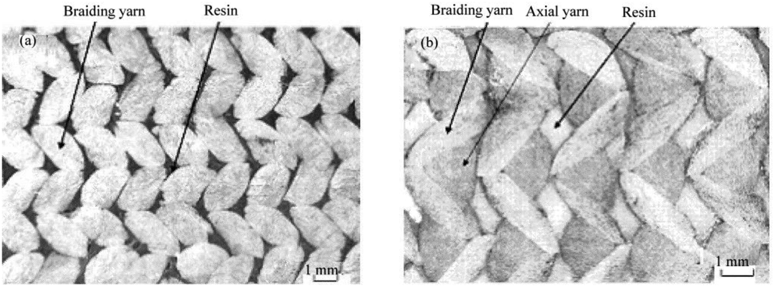

For 3D4D braided composites, there are only braiding yarns in the fabric, a and b are the major and minor radii of the ellipse, as shown in Figure 5(a). If the width of the braided preform is W
m
, and the thickness of the preform is W
n
, the minor radius b can be calculated as follows:


When the yarns are jamming and contact each other, the relationship between a and b is:
9

The braiding angle on the surface, denoted by α, is usually easy to measure. The relationship between α and γ is


For 3D5D and 3DF5D braided composites, the fabric contains both braiding and axial yarn. The cross-section of an axial yarn is shown in Figure 5(b). Defining r is the ratio of the side length of the square to the minor radius b of the ellipse, and is called section size factor of axial yarn. Assuming the yarn packing factor κ is the same for all yarns, the cross-section area S and the braiding pitch h can be expressed as


The major radius of the ellipse a, the length and width of the unit cell for 3D5D and 3DF5D braided composites can be calculated by


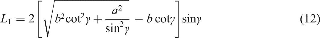
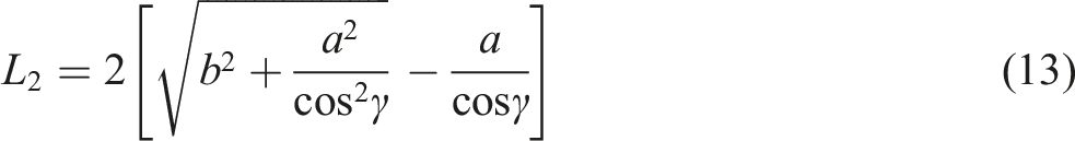
For 3D4D, 3D5D and 3DF5D braided composites, the side lengths L1 and L2 of the octagon in Figure 5(a) are
According to the above parameters, the mesoscopic RVE can be established by a bottom-up modeling method, as shown in Figures 6, 7 and 8. RVE for 3D4D braided composites (a) Yarn (b) Matrix. RVE for 3D5D braided composites (a) Yarn (b) Matrix. RVE for 3DF5D braided composites (a) Yarn (b) Matrix.


Finite element models of RVEs
Due to geometrical regularity of the RVE of yarn, the hexahedral element SOLID186 in ANSYS was selected to mesh the model (shown in Figure 9). However, the geometry of the unit cells of 3D braided composites is relatively irregular, so the tetrahedral element SOLID187 was chosen for meshing this model. Figure 10 shows the finite element model of 3D4D braided composites. It is noted that in order to apply periodic boundary conditions later, the opposite surfaces of both the RVE models were meshed identically. FE model of RVE of yarn. FE model of RVE of 3D4D braided composites.

Finite element method on thermo-mechanical analysis
Periodic boundary conditions
For periodic structures composed of RVEs, it is generally assumed that each RVE has the same deformation so that periodic boundary conditions should be applied on the RVE models. 55
For example, Figure 11 shows a cubic RVE model of a material, where x1 and x2, y1 and y2, z1 and z2 are the corresponding nodes on the opposite surfaces of the RVE in x, y and z directions; u, v and w represent the displacement in the x, y and z directions. Then, the periodic boundary conditions of z-direction tension can be expressed by: Periodic boundary conditions of z-direction tension of a RVE model.
The periodic boundary conditions can be applied using nodes coupling(CP) or constraint equations(CE) command defining in ANSYS. If a set of nodes have some of the same degrees of freedom, the coupling command will be used to constrain these nodes. On the other hand, if there is a certain relationship between the degrees of freedom of some nodes, a constraint equation will be defined.
Elastic constant and CTE
The stress-strain relationship of the material under thermal environment can be expressed as:

Assuming

According to the relationship between the flexibility tensor and the stiffness tensor, the strain-stress relationship is

Then, by applying six sets of independent constant strain periodic boundary conditions on the unit cell according to Reference 56, the flexibility tensor is obtained, then the engineering elastic constants of the material are calculated.
When the stiffness tensor is obtained, assuming

Setting

As
Micro-stress under thermo-mechanical coupling
Firstly, the micro-stress under free thermal expansion is discussed. In the process of heating or cooling, the mismatch of CTE between yarns and matrix will cause residual thermal stress inside the structure. According to the calculated CTE from equation (19), the overall deformation of an RVE model can be determined. Then, the residual stress in the RVE of Figure 11 can be calculated by applying the periodic boundary conditions as follows:

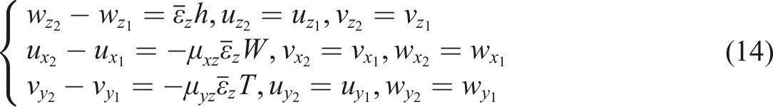
For miro-stress calculation under the thermo-mechanical coupling loads, both the mechanical and the thermal deformation of the RVE should be considered. For example, when the z-direction tensile and the thermal loads are applied to the RVE, the periodic boundary conditions in Figure 11 become:

Periodic boundary conditions for thermo-mechanical analysis.

Two-scale method for thermo-mechanical analysis
In this paper, a two-scale finite element method based on microscopic and mesoscopic RVE models is used to study the thermo-mechanical properties of 3D4D, 3D5D and 3DF5D braided composites. The process of numerical simulation includes the following seven steps:
Create the microscopic finite element model of the RVE of yarns as shown in Figure 9.
Apply six sets of constant strain periodic boundary conditions on the microscopic RVE model and calculate the elastic constants of the yarn by finite element method via equation (17).
Apply equal displacement periodic boundary conditions and overall temperature increment on the microscopic RVE model and calculate the CTE of the yarn by finite element method via equation (19).
Regard the yarns in 3D braided composites as homogeneous materials, and define their material properties by using the elastic constants in step 2 and the CTE in step 3, then create the mesoscopic FE model of the RVE of 3D braided composites as shown in Figure 10.
Similar to step 2, calculate the elastic constants of 3D braided composites based on the mesoscopic RVE model.
Similar to step 3, calculate the CTE of 3D braided composites based on the mesoscopic RVE model.
According to equations (20) and (21), apply the periodic boundary conditions considering thermal and mechanical deformation on the mesoscopic RVE model, and then simulate the micro-stress under free thermal expansion and the loads of thermo-mechanical coupling.
Results and discussion
Braiding angle, fiber volume fraction and braided structure have an important influence on the thermo-mechanical properties of 3D braided composites. Therefore, in this paper, a set of software for parametric thermo-mechanical coupling analysis of 3D multi-directional braided composites based on two-scale models is developed by the APDL language on the platform of ANSYS. Based on this software, the elastic constants and the CTE varying with braiding parameters are discussed in detail. Furthermore, the thermal stress is simulated and the effect of temperature is studied.
Original material and structural parameters

Structural parameters of specimens of tensile experiments. 1

Structural parameters of specimens of thermal expansion experiments. 36

Prediction on elastic constants

It can be seen that there is a good agreement between the longitudinal elastic modulus E z and the longitudinal Poisson’s ratios μ zx between the predicted and the experimental data for the tensile specimens. The error becomes larger with the increase of braiding angle, which is because the influence of surface cell and corner cell is not considered in the calculation process. However, for the braided composites with large braiding angle, the surface and corner braiding angles are much smaller than the interior braiding angle, so the actual longitudinal elastic modulus of specimens is usually larger than the predicted value based only on the interior unit cell model.
Prediction on CTE
Comparison of the CTE between predicted and experimental data. 36

Simulation on micro-stress
Based on the numerical method introduced in the section of “Micro-stress under thermo-mechanical coupling”, the micro-stress under free thermal expansion and the loads of thermo-mechanical coupling can be simulated, which reflects the heterogeneity of the materials. Supposing that there is no structural deformation at room temperature, Figures 12 and 13 show the longitudinal residual stress of yarns and matrix when specimen numbered TE3 expanded freely at different temperatures. As the yarns and matrix are transverse isotropic and isotropic respectively, and the main damage pattern of yarn is axial breakage, the axial stress σ1 of yarns and the stress σ
z
in the braiding direction of the matrix are shown in these figures. Residual stress σ1 of yarns at different temperatures (a) ΔT = 60°C (b) ΔT = 120°C (c) ΔT = 180°C. Residual stress σ
z
of matrix at different temperatures (a) ΔT = 60°C (b) ΔT = 120°C (c) ΔT = 180°C.
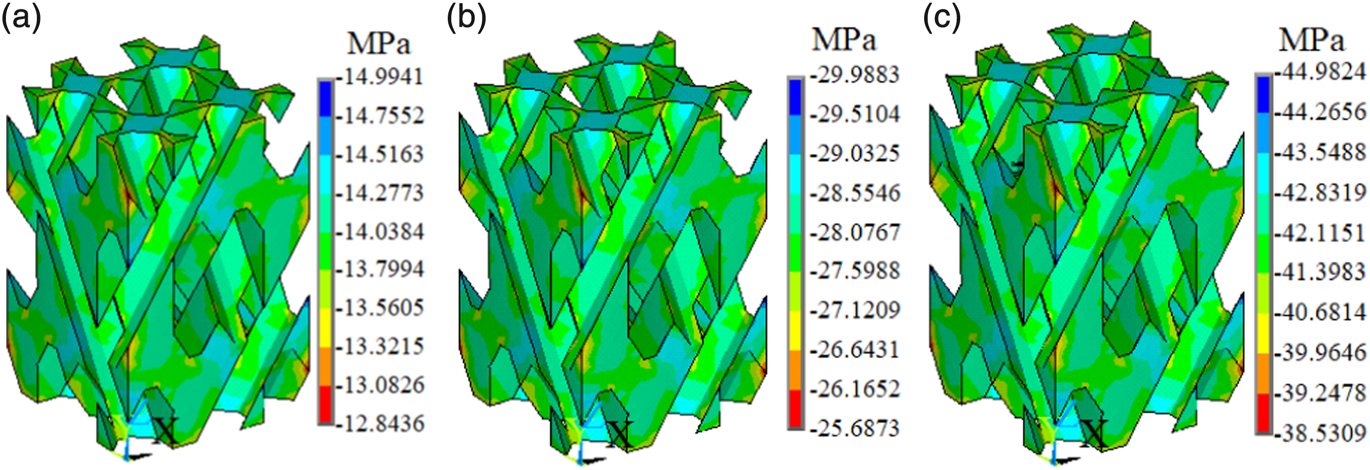
From these two figures, it is observed that at free expansion, the yarn is stretched but the matrix is compressed longitudinally. This is because the longitudinal CTE of yarn is much smaller than that of resin matrix, as shown in Tables 2 and 6. When the temperature rises, the thermal expansion of the matrix is inhibited and the matrix is compressed, whereas the yarns are stretched. Meanwhile, although the unit cell has almost the same stress distribution characteristics at different temperatures, the absolute value of residual stress increases obviously with the increase of temperature, as shown in Figures 12 and 13.
Figures 14–16 are the micro-stress simulation of mesoscopic RVE under longitudinal tension at different temperatures. Miro stress of RVE under tension ( Miro stress of RVE under thermo-mechanical coupling ( Miro stress of RVE under thermo-mechanical coupling (
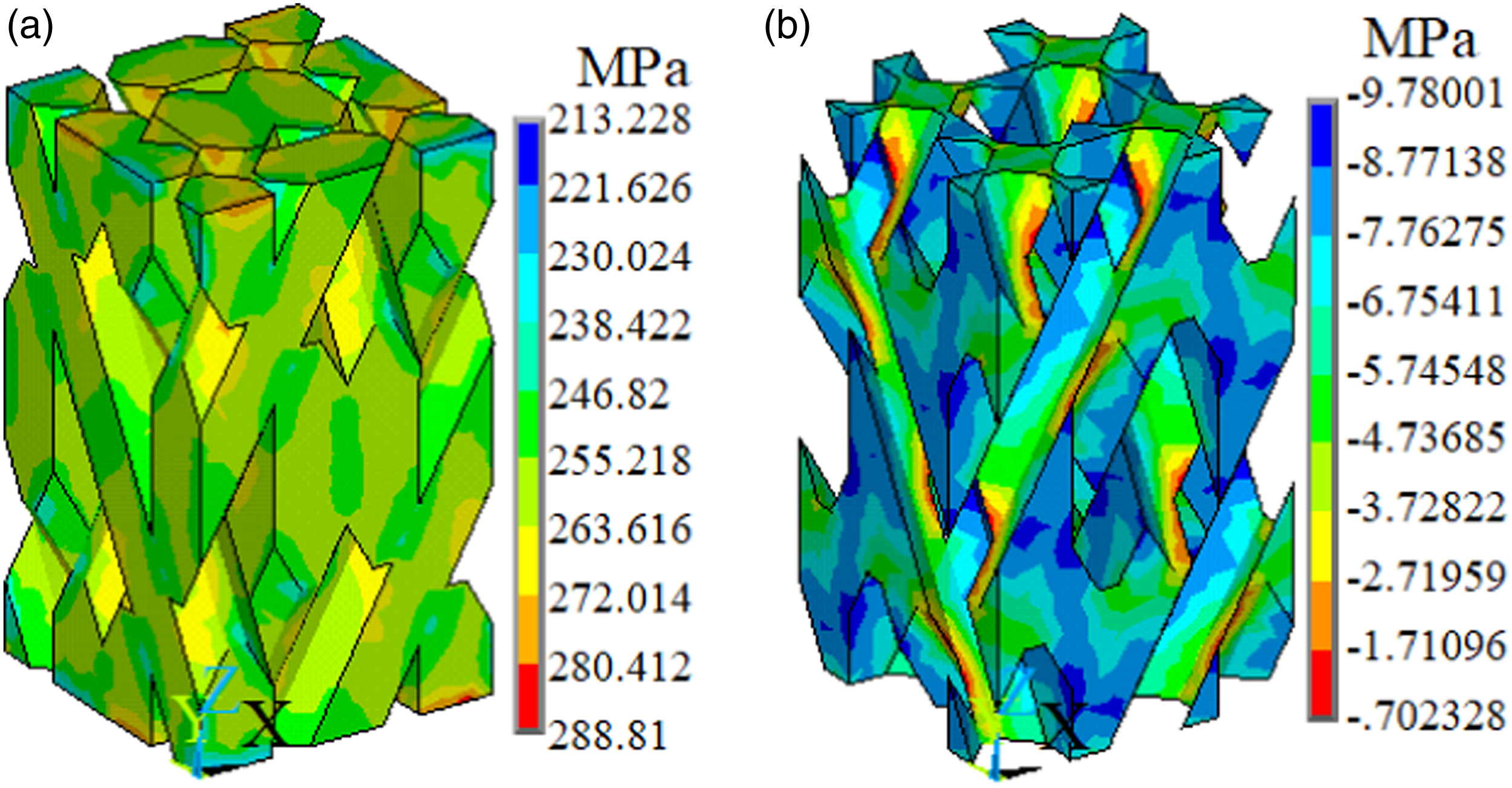
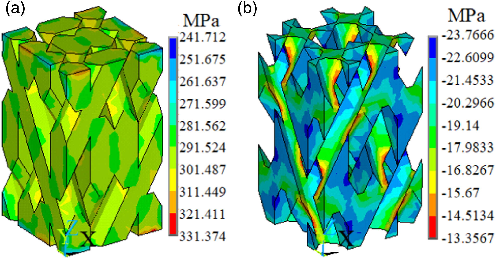
It can be seen that with the increase of temperature, the longitudinal micro-stress in yarns increases gradually but the stress in matrix decreases. When the tensile load is small, the stress in the matrix is compressive stress. This is mainly because the residual stress caused by temperature increment redistributes the micro-stress in the unit cell.
Discussion of braided structures and braiding parameters
In this section, assuming the components are T700-12K carbon fiber and TDE-85 epoxy resin, the influence of braiding angle, fiber volume fraction and braided structure on the elastic and thermal expansion properties of 3D braided composites are discussed.
The engineering elastic constants of 3D4D, 3D5D and 3DF5D braided composites varying with the braiding angle and fiber volume fraction are shown in Figure 17, where Vf represents the fiber volume fraction. Influence of braiding parameters on the elastic constants (a) Longitudinal elastic modulus (b) Transverse elastic modulus (c) Longitudinal shear modulus (d) Transverse shear modulus (e) Longitudinal Poisson’s ratio.
Figure 17(a) presents the variation of the longitudinal elastic modulus with the braiding parameters. It is observed that the longitudinal elastic moduli of all braided structures decrease with the increase of braiding angle, but increase with the increase of fiber volume fraction. Meanwhile, with the increase of axial yarn content, the longitudinal elastic modulus increase obviously.
From Figure 17(b), it can be seen that the transverse elastic moduli of the three braided structures all increase with the increase of the braiding angle or the fiber volume fraction, but the transverse modulus of the 3D4D braided composites increases more significantly.
As shown in Figure 17(c) and (e), the longitudinal shear modulus and the longitudinal Poisson’s ratio have similar variation characteristics with the increase of the braiding angle, that is, they increase first and then decrease. However, the fiber volume fraction has a great effect on the longitudinal elastic modulus but has little effect on the longitudinal Poisson’s ratio of the three materials. Furthermore, with the increase of axial yarn content, both the longitudinal shear modulus and the longitudinal Poisson’s ratio decrease.
Figure 17(d) depicts that with the increase of the braiding angle, the transverse shear modulus also increases and the increase is much slower for 3D4D braided composites. At the same time, the transverse shear modulus increases significantly with the increase of the fiber volume fraction, especially for 3D5D braided structures.
Figure 18 shows the influence of braiding parameters on the CTE of 3D4D, 3D5D and 3DF5D braided composites. Comparing the two figures, it can be seen that the longitudinal CTE of these materials is usually much smaller than the transverse CTE, and the value of the longitudinal CTE is basically negative or zero when the braiding angle is small. This is because the yarn has a major effect on the longitudinal CTE and this effect is more obvious for the composites with small braiding angles. As the longitudinal CTE of carbon fiber is negative, when it is combined with the matrix with positive CTE, the material will have a small negative value or zero value of the longitudinal CTE. Influence of braiding parameters on the CTE (a) Transverse CTE (b) Longitudinal CTE.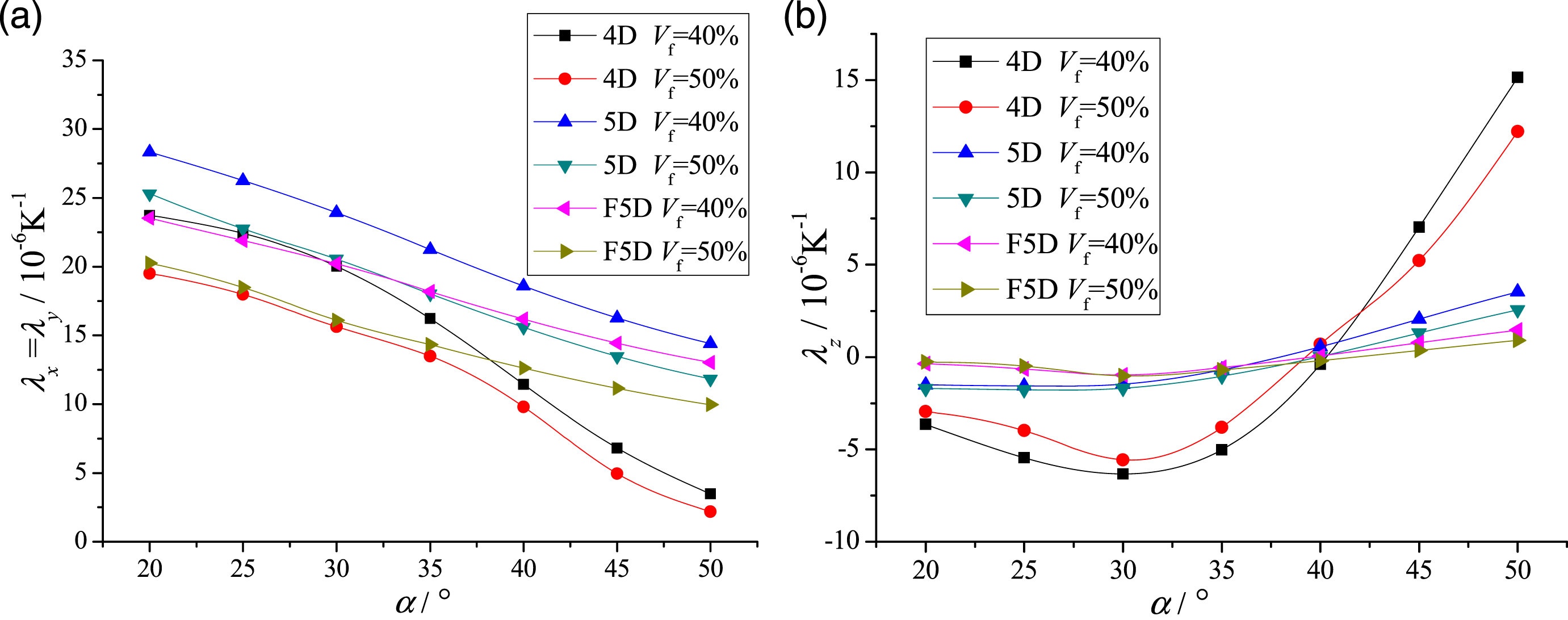
From Figure 18(a), it can be seen the transverse CTE of three braided structures all decrease with the increase of the braiding angle. In general, when the fiber volume fraction is the same, the transverse CTE of 3D5D braided composites is the largest, followed by 3DF5D materials, and the transverse CTE of 3D4D materials is the smallest and decreases rapidly with the increase of the braiding angle.
From Figure 18(b), it is observed that the longitudinal CTEs of three braided structures have similar variation characteristics with the increase of the braiding angle, that is, they decrease first and then increase. However, when the fiber volume fraction is the same, the 3DF5D braided composites have the smallest change, followed by the 3D5D materials, and the 3D4D materials have the largest change. Particularly, the longitudinal CTE of 3D4D braided composites increases rapidly with the increase of the braiding angle when the braiding angle is greater than 35°, which is because when the braiding angle is large, the matrix plays a major role in the longitudinal thermal expansion performance of the composites. It indicates that the axial yarn content has a great influence on the longitudinal thermal expansion, and the higher the axial yarn content, the more stable the longitudinal CTE.
Furthermore, it is not hard to find that the corresponding braiding angle of zero longitudinal CTE of any braided structure is basically about 40°, and in most cases this zero point of braiding angle will increase with the increase of fiber volume fraction. These data can provide reliable suggestions for the optimal design of zero thermal expansion of 3D braided composites.
Conclusions
Based on the the theory of stress-strain relationship considering thermal expansion and the method of the periodic boundary conditions, the thermo-mechanical behavior of 3D multi-directional braided composites were analyzed systematically by APDL parametric programming of ANSYS. The effect of braided structure, braiding angle, fiber volume fraction, and temperature on the simulation results were discussed. The main research conclusions are summarized as follows: 1. The braided structure has a great influence on the mechanical and thermophysical properties of 3D braided composites. With the gradual increase of axial yarn content from 3D4D to 3D5D and then to 3DF5D braided composites, the longitudinal CTE decreases significantly and becomes much more stable with the change of the braiding angle. This indicates that the longitudinal thermal expansion performance can be significantly improved by adding axial yarns. 2. The thermal expansion property can be optimized by adjusting the braiding angle. The braiding angle corresponding to the zero longitudinal CTE of all three braided composites is basically about 40°, which will increase with the increase of fiber volume fraction in most cases. In addition, the transverse thermal expansion performance can be significantly improved by increasing the braiding angle. 3. With the increase of fiber volume fraction, the tensile and shear moduli of the 3D braided composites increase significantly, and the transverse CTE decreases obviously. However, fiber volume fraction has little effect on the longitudinal thermal expansion properties of these materials, especially for 3D5D and 3DF5D braided composites. 4. For longitudinal tension under thermal environment, with the increase of temperature, the longitudinal micro-stress in yarns increases but the stress in the matrix decreases, which is due to the residual stress caused by temperature increment redistributing the micro-stress in the composites.
Future work will focus on the progressive damage and strength analysis of 3D multi-directional braided composites under thermal environment in the subsequent research.
Footnotes
Declaration of conflicting interests
The author(s) declared no potential conflicts of interest with respect to the research, authorship, and/or publication of this article.
Funding
The author(s) disclosed receipt of the following financial support for the research, authorship, and/or publication of this article: The authors wish to acknowledge the support received from the Fundamental Research Funds for the Central Universities (Grant no. 2019XKQYMS08).