
Abstract
Damage, generated during drilling processes, will affect the material integrity and further delamination through the fiber-reinforced composite cross-section. Drilling is necessary for the assembly processes of composite parts. This article deals with the effect of the weave parameters on the drilling mechanism. The mechanism of the yarn shearing ring drilling was investigated, and the quality of the drilled hole was carefully examined for different drilling conditions. Set up for measuring the power consumption during the drilling of different samples as well as the value of the thrust force was constructed. In the drilling of fabric-reinforced polymer composite, the torque, thrust force, and delamination factor are depending directly on fabric design parameters. It was shown that both, drilling power and drilling thrust force, are proportional to the total specific fabric stiffness. Delamination caused by drilling thrust is one of the most problematic defects after drilling laminate composite. A drilling Index was developed and could be used to evaluate the effect of the fabric design of laminate on its composite drilling performance. It was revealed that significantly higher drilling power is needed for the plain weave fabric design than for the other fabric designs of the same unit repeat as well as for the laminates of high fiber volume fraction and high total flexural rigidity. Analysis of the delamination factor and the drilling power showed a high correlation with total fabric flexural rigidity.
Keywords
Introduction
Composites present effective constructive materials in the industry giving their excellent properties. Composites allow the manufacture of large integral structures, therefore reducing the number of parts and mechanical fasteners needed to assemble them. The concept of designing material to give the desired set of material properties has received growing acceptance for composites. The material design significantly affects the structural process.1,2 Laminate is a widely used geometry for continuous fiber-reinforced polymer composites. Laminates are fabricated of a single ply or of many plies, in which all fibers often have the same direction. Fibers are much stronger and stiffer than the matrix in the composite material, so a ply is stiffer and stronger in the fiber direction - it is anisotropic. Joining is an essential operation for the assembly of various parts. Most parts, based on polymer composites, are fabricated near a neat shape. The composite components need to be joined together to obtain the intricate structure. Recent scientific and technological progress in welding and joining has shown the potential to revolutionize the way designers and engineers combine dissimilar materials. The joint, used in a composite structure, is usually the weakest point of the structure and thus, determines the structural efficiency. The possibility of fully exploring the properties of varied materials in the same structure instead of relying on only one strong material or creating material reinforcement of critical areas opens a range of new structural concepts.3–5 Drilling operations on composite laminates are essential for fastening with other materials to have useful outcomes in the industry. This process requires turning, milling, and drilling machining processes based on the component requirements. In the aerospace industry, 60% of the rejections of fiber-reinforced composites are caused by improper cutting processes 6 and 40% of the material removal is done by drilling operations. 7 Hence, drilling is an important process among others, and it requires particular care to keep the high structural strength of composite structures for long-term usage. 8
Unconventional drilling methods such as laser machining,9,10 water-jet machining,11,2 and electrical discharge machining are currently used for the treatment of polymer composite materials. However, the most developed and most often used methods are mechanical drilling operations using conventional or special drill bits.12–18 The fastening efficiency and excellence rely on the drilled hole quality. Producing error-free precise holes is wanted to ensure high joint strength during assembling the materials by riveting or bolting. Nevertheless, undesirable damages during machining are prone to delamination, cracking, fiber pull-out, fiber fuzzing, matrix chipping, and de-bonding. Thermal damage by drilling drastically reduces strength against fatigue, thus degrading the long-term performance of composite laminates.19–23 Delamination might be introduced by three mechanisms: punching out of the uncut layer near the drill exit, peeling up of the top layer, and through thermal stress. From there, exit ply delamination is the most common mode when drilling fiber-reinforced polymer composites. Exit delamination occurs when the drill progresses toward the bottom of the laminate where the uncut thickness of the laminates decreases.24,25 Delamination is a disadvantageous and dangerous phenomenon. 26 Optimum joint proportions have evolved from invariant relationships between structural tension, shear, and bearing strengths. Because of the essential differences in properties caused by the anisotropy and inhomogeneity of composites, design policies that evolved for metal joints cannot be applied directly to composites. The basic strength and modulus relationships on which metal joint technology is based are variables in the composite structural design process. Thus, the design of optimum joints in reinforced composites must start with the selection and arrangement of the basic material constituents. 27
Recently, research studies have investigated the role of drilling process parameters, including cutting speed, feed rate, drill bit geometry, and composition, on the output product quality of laminates, which are the most utilized in aerospace applications.
28
The different composite parts may be connected by using techniques for joining composite materials to themselves and other materials. Adhesive bonding, mechanical fastening, a combination of bonding and fastening, and mechanical fastening are usually needed to drill the composite plates. The mechanism of yarn cutting during drilling is different from the mechanism of fabric cutting,
29
since the cutting edge of the drill rotates and moves downwards during the drilling of a circular hole. Composite reinforcements can be in various forms such as fibers, fabric, and particles. Achieving a minimum amount of damage is a key issue for drilling fabric-reinforced polymer composite (FRPC) composites.30–36 Earlier researchers mostly agree that mechanical drilling requires the selection of optimum cutting operation parameters, i.e., cutting speed (spindle speed) and feeding rate, to avoid excessive forces affecting the surface integrity of FRPC. In addition, it is not practical to manipulate the cutting parameters in peck drilling strategies. This can be explained by observing the hole quality of a tool drilled to a certain depth inside the hole at various speed feed combinations.
37
Due to its specific mechanical properties, fiber-reinforced polymer composite is widely used as a structural material in various industries. In the scope of aerospace industrial uses of this material, thousands of holes must be machined for purposes of assembly.
38
Many factors affect the quality of the hole of the composite material drill performance
39
as shown in Figure 1. Each factor is a function that has parameters influencing the quality of the drilling process. For instance, hole quality is a measure of crack formation, surface roughness hole accuracy, dimensional error, roundness error, and damage to surface layers. Factors affecting the drilling performance.
The analyses of the literature indicate that, although the primary manufacturing techniques for fabricating the products based on FRPC are well developed, their secondary manufacturing in terms of machining and joining still requires extensive research efforts. The hole drilling becomes an inevitable machining operation to enable composite fastening. The importance of the composite material drilling problems is met with limited investigations concerning the effect of the fabric design on the drilling process of such composites. That is the main objective of this work.
Material and method
Fabric specifications
Specifications of woven fabric samples.

Mechanical properties of fabrics.

aStandard deviation.
Composite samples preparation
Composite samples were fabricated using the hand lay-up method, in which a release polymer was sprayed on. Polymeric thermosetting material (Polyester) which has low viscosity as matrix material was used. The matrix consists of two chemical components. The blending ratio of the two components is 100 base (unsaturated polyester): 1 hardener (MEKP (methyl ethyl ketone peroxide)). During the consolidation phase of liquid composite molding of 2D woven fabric, the composite was subjected to pressure to get the final form. In this phase, the final fiber volume fraction of the composite can be reached. The yarns were pressed to reduce their volume. The final thickness depends on the compactness of the yarns and the fabric structure. 40 Two sets of composites of different fiber volume fractions and the number of laminates were prepared.
In the case of the same material in both weft and warp directions, the volume fraction of the composite will be: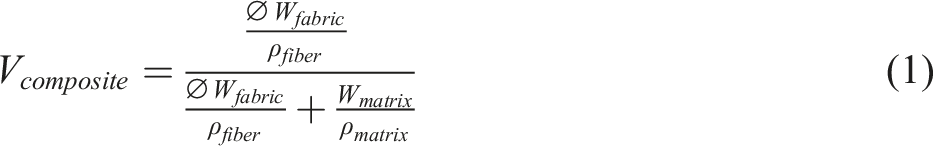

The matrix volume fraction is V matrix = W matrix /ρ matrix .
Then, the volume fraction of the composite can be calculated as:
V
composite
= V
fabric
total
/(V
fabric total
+ V
matrix
), substitute with the value of Vfabric total, then
In the case of a fabric-reinforced composite made of matrix and fibers of the same density:
While, in the case of different types of fibers used in warp and weft yarns, then:
The fabric-reinforced polymer composite samples specifications.

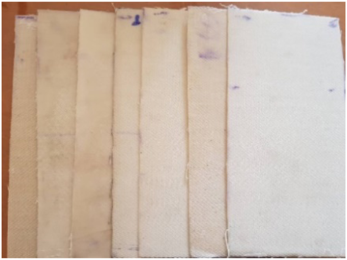
The composite samples.
Set up for measuring the thrust force and drilling energy
Design of drilling set-up apparatus
The set-up records two readings of applying the thrust force on the tested specimen using a thrust force sensor and the required energy to drill a hole by power indicator. A rectangular composite test specimen is fixed on the drilling holder opposite the drill tip. Enough thrust force is applied to allow the breakthrough of the drill. The sample holder is fixed on the table, pressed, and stressed to the drill point by a predetermined thrust force, measured by the load sensor. The drilling energy was measured continuously during the process. Figure 3 shows a sketch of the drilling set-up. Five holes were drilled in each sample. Setup for fabric drilling force and energy measurement.
Test procedure
The drilling energy of a sample depends on the thrust force value. In the testing procedure, the value of the thrust force, which allowed the drill to complete the hole through the thickness of the tested sample, was chosen. In all cases, the drilling feed rate was kept constant at 0.2 mm/rev, and the spindle speed at 1000 rpm.
The following steps were applied in each sample test: - Fixing the composite specimen on the sample holder. - Turning on the drilling device until the power indicator shows that the power of the drilling device reaches its stable state. - Determining the suitable thrust force for each sample by applying gradually and increasing its value till reaching the required load to drill through the composite specimen entirely at constant feeding velocity for all tested samples. - Study the hole performance by taking images of drilling holes.
Each sample was tested in the following forms:
1. Fabric form
2. Fabric-reinforced polymer composite
3. Multi laminates fabric reinforced polymer composite
Five holes are drilled along each tested composite with 30 mm in between.
Measures defining the drilled hole’s quality
Quality control of holes in the parts made of a composite material still causes many technical difficulties. These complications are the result of delamination of the material and internal damage, often invisible from the outside Figure 4.
26
Drilled hole shapes.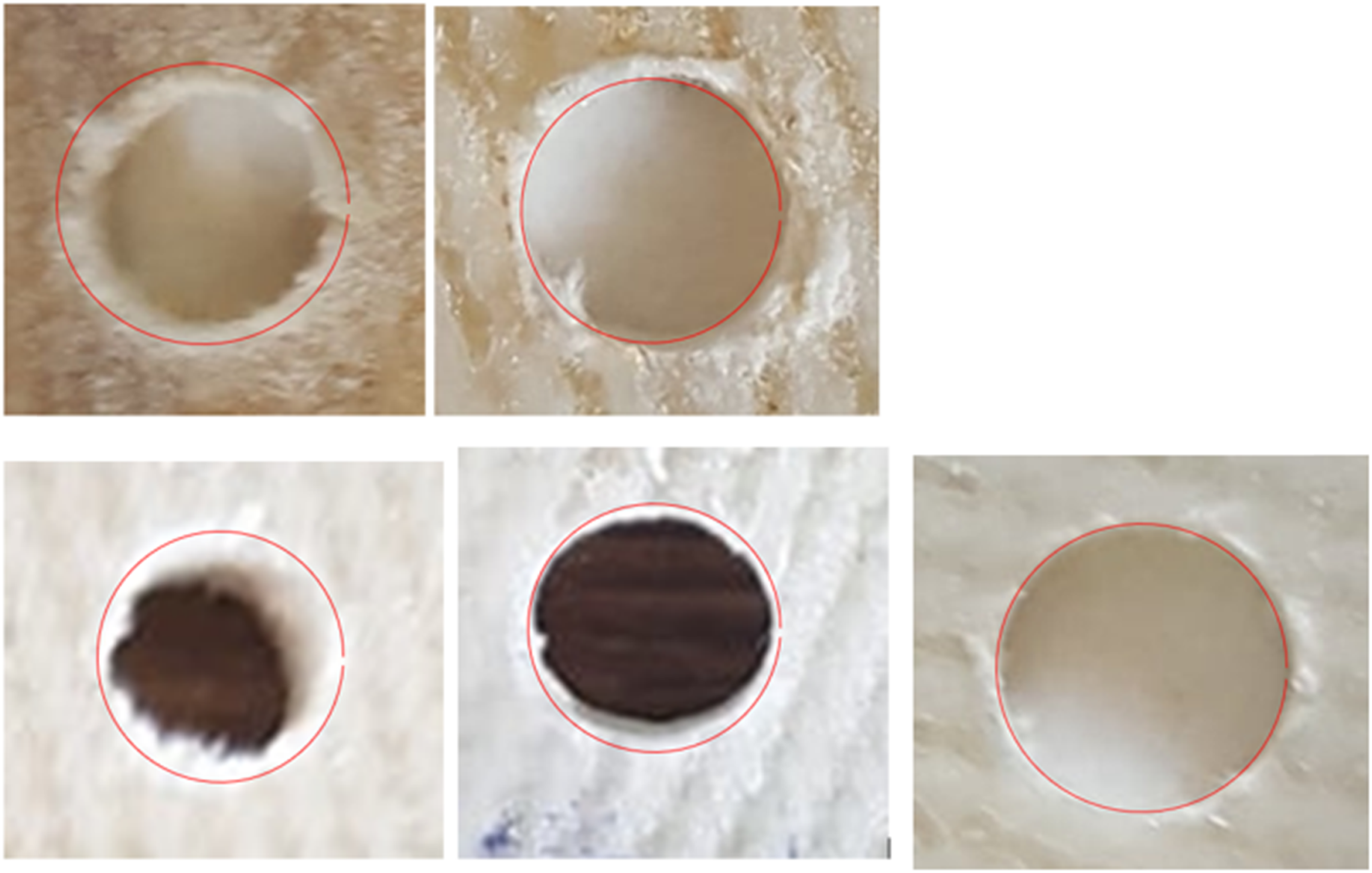
There are several ways to measure the quality of drilled holes based on microscopic images such as shown in Figure 5: Methods of evaluation of the drilled hole’s quality.
1. The burr factor
The analysis of the hole photos shows that in the case of FRPC there are protruding fibers inside the hole wall as shown in Figure 4.
The burr factor (B) is expressed in the form of:
B = 100(area of the fibers/area of the hole)
It can be applied to characterize the quality of machined holes concerning the number of uncut fibers, figure 5-(a) shows examples of the hole shape. To calculate the value of B, a simple analysis may be used.
B = 100(area containing fibers/area of the hole) = (dn 2 – da 2 ) 100/dn 2
2. The uncut yarns coefficient
Figure 5(b). shows a piece of yarn that is still holding onto the wall of the hole. The percentage of the number of uncut yarns to the total number of yarns around the hole may define the hole quality.
3. The deviation between the nominal diameter and the measured diameter
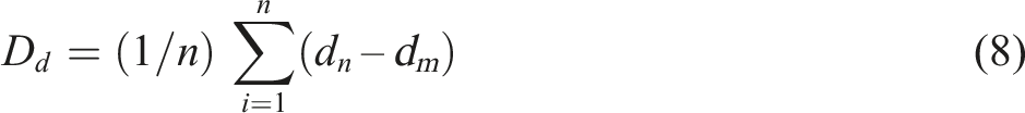
4. The delamination factor
The delamination factor was calculated at the drill entrance only. The delamination factor is defined as the ratio of the maximum diameter of the observed damage zone (d
max
) to the nominal diameter of a drilled hole (d
o
), figure 5-(c). The delamination factor is computed by the following:
The delamination factor is the most popular used measure of hole quality evaluation.41,42
Deviation from the nominal diameter
The difference from drill diameter, Figure 5(d).
Results and discussions
Force analysis of the drilling process
Drilling of fabric-reinforced polymer composite materials is different than the drilling of metals as the drill must pass alternatively through the polymer matrix and fabric (reinforcement) which have different properties. The fabric consists of yarns made of short or continuous fibers. Figure 6(a) shows a section in the drilled hole in FRPC. (a), (b), (c). The cutting force during the drilling of FRPC.
In the woven laminates, the warp and weft yarns are perpendicular to each other. Each yarn in both directions will meet at least the cutting edge twice per revolution Two for the warp yarn fibers at edge position angle equal 0 and 180°, and two for the weft yarn fibers at edge position angle equal 90 and 270°. 43 Figure 6(b) shows the cutting force of the warp and weft yarns during the drilling of FRPC.
During drilling, thrust force F th is applied which is resolved into two components: the thrust force induced by the contact of the cutting lips with the laminate FI, and the force corresponding to the contact of the chisel edge with the laminate FII. The thrust force, generated by the chiseling edge, represents approximately 50% of the total thrust force F th . 44 This means the increase in the required value of FII, the higher value of drilling thrust force is needed, therefore, increasing the probability of delamination of the composite material. The value of the cutting force depends on both: the resistance force to cutting fabric material and the shearing of the polymer matrix, as well as the thickness of the composite and the number of laminates used. The fabric used in the formation of the FRPC may be woven, knitted, braided, or nonwoven. Each has a different layout of the fibers material in the fabric space, which leads to a different mechanism for cutting the fibers during the drilling. 45 The FRPC composite is often manufactured in near-net-shape products to achieve dimensional tolerance and assembly requirements. 46 Drilling is the most important and frequently used operation in the industry for finishing composite structures. A special concentration was made to inspect and characterize the phenomena of various yarn cutting promoted in composite material drilling when using different weave structures. FRPC drilling operation is different than that of the homogenous materials as the cutting-edge interacts with fiber and matrix simultaneously. The flank face of the tool, the flank surface produces the main cutting edge, rubs on the composite material, and develops high frictional contact due to the elastic recovery of broken fibers, fiber burr, or unbroken yarns. The total force, required to drill a hole in a composite material, will be equal to the sum of the cutting force of the matrix material (Fm) plus that of the fabric material (F total ) and the friction between the drill bit and surroundings during the hole drilling (F f ), Figure 6(c).
Assume the cutting force of the matrix is F m , then
Total shear force during drilling
Then the total drilling force will be
The moment of drilling forces Mc = 0.5 F D
drill

The thrust force value depends on the drill speed, feed rate, and the required total drilling force (F). The magnitude of cutting and thrust forces are a function of tool geometry (rake angle, included angle, edge radius, etc.) and cutting parameters.
Drilling energy
In the case of using fabric as reinforcement, the drilling process is different due to the value of thrust force being higher than for the other types of materials. This may cause delamination of the composite material.
Assuming the fabric is formed without intersections, consequently, the drill will cut all the warp and weft yarns in the area of action of the chisel edge when the drill rotates. Subsequently, the total cutting force that acts on the edge of the drill will be equal to the sum of the cutting forces of the warp and weft yarns. Moreover, the vertical force on the drill (thrust force) will cause a deformation of the composite during the cutting process.
The total cutting energy is
The last two energies part could be neglected for thin composite producing no fuss fibers on the inner surface of the hole.
Fabric unit cell drilling force
During the drilling, the composite will be cut by drill pit chisel edge, cutting lips, and the leading edges. The chisel edge and the cutting lips are the main cutting areas that work in material removal, while the cutting on the leading edge is referred to as reaming, the hole surface. 36 The main cutting edges are the cutting lips, which affect the thrust force and power consumption. The drilled area has warp and weft yarns to be cut during the passage of the drill through the composite thickness.
The unit cell is an essential part of textile modeling, with the assumption that both the warp and weft yarns have similar geometry and material properties. Starting with the plain weave structure, in Figure 7, the chisel edge has a circle path depending on the drill diameter D
drill
. Consequently, two cutting lines may have occurred, which shows that the drilling force is different depending on the cutting II line path. The yarn may be cut as in the position of cutting line I, both warp and weft yarns will be cut, while in the second cutting line II, the cutting will be at the crossing of both warp and weft yarns. The value of the cutting force will be higher in the case of line. The plain weave fabric and the cutting line path.
In the position of cutting line I, both warp and weft yarns will be cut separately, since the chisel edge will be in contact with one set of yarns, while in case line II, both warp and weft yarns will be cut by the chisel edge at the intersections at the same time.
Case 1
This will take place when the radius of the drill is equal to
If a 1 and a 2 are not integer numbers, the drill edge cannot cut a weft and warp interlacement.
The yarns of the weft and warp at the interlacement will be pressed together under tension created in each yarn, so, the packing density of the yarns will be changed and may affect the cutting force. Since the number of warps/cm (1/p
2
) and weft/cm (1/p
1
) is so large, it can take the number of interlacements that will be equal to the number of interlacements in a fabric length (D
drill
) in each direction, approximately. So, the total number of interlacements is: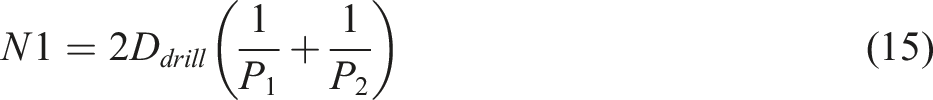
Assume f1 is cutting force of one yarn interlacement implanted with polymer, then the total cutting force of the fabric laminate is the cutting force of interlacements (F
int
):
Case 2
If a
1
and a
2
are non-integer numbers, the cutting of the warp and weft yarns interlacements will be approximately equal to
Then the cutting force of interlacements is
Figure 8 shows the different situations of fabric drilling for different fabric designs, which indicates the effect of fabric design on the cutting force due to the change in the values of N1 and N2. Drilling different fabric structures.
In the case of a multi-laminates composite, which may consist of several fabric layers of the same properties or different fabric structures and materials, the cutting force can differ and be calculated separately for each enforcement layer.
R 1 = a 1 p 2 , a 1 : integer numbers, R 2 = a 2 p 2 , a 2 : non-integer numbers
R 1 = a 1 p 2 , a 1 : integer numbers, R 2 = a 2 p 2 , a 2 : non-integer numbers
R1= a1 p2, a1: integer numbers, R2 = a2 p2, a2 : non-integer numbers
The value of the total drilling force of the fabric reinforcement force per one revolution of the drill bit
Case 1
During the rotation of the drill under the pressure, the sharp edge will start to cut the yarns in its path either in the weft or warp direction. The total cutting force will be equal to the sum of the cutting forces of the warp and weft yarn.
If the radius of the drill R = a 1 p 2 or R = a 2 p 1 and a1 and a2 are integer numbers, then the total cutting force will be equal to F1. 47
The cutting force for the unit of plain weave
If the shear stress τ(0) of the weft and warp yarn is the same and k
1
= k
2
, n
warp
= n
weft
, and the yarn count of both the warp and weft is equal, the total cutting force will be

Where p 2 =1/n warp , p 1 =1/n weft , k 1 is the warp fractional cover factor, k 2 is the weft fractional cover factor, C 1 is the warp yarn crimp, C 2 is the weft yarn crimp, n warp is the number of warp yarns per cm, and n weft is the number of weft yarns per cm. Suffixes 1 and 2 to the above parameters represent warp and weft threads, respectively.
Case 2
If R = a
1
p
2
or R = a
2
p
1
a
1
and a
2
are non-integer numbers, then


A similar approach can be used for the other fabric designs, taking into consideration that the number of intersections differs according to the fabric design. 47 For different fabric designs, the number of intersections per repeat can be used to compare with the other fabric designs. The plain design unit has two yarns in each warp and weft direction while the twill design 1/2 has three yarns in each warp and weft direction. Consequently, for having the same number of yarns per unit area with complete repeats for plain and twill 1/2 designs, it must be taken three repeats of plain to compare with two repeats of twill 1/2. Then the value of cutting force for plain design (F1) will be equal to 3/2 = 1.5 that of twill design. In this case, the cutting force of the twill design = 0.667 F1. While for twill 1/3 the cutting force = 0.5 F1, while F2 is the same.
Analysis of the effect of fabric structures
The drilling power
The drilling processes of the fabric are depending on the fabric properties as well as the physical properties of yarns. The mechanism of the fabric deformation under the thrust force will cause both deflection of the fabric as well as fabric shearing in the area around the drill bit.
48
Forces acting on the yarns in the zone of drilling before cutting differ from the moment the tip of the drill bit touches the fabric surface and continuously increase as the drill’s tip moves down. The rotation of the drill will be resisted by the jammed area near the point of the drill penetration. As the drill starts to shear the warp and weft yarns in the surrounding area, both yarns will be released. Consequently, the fabrics which have a lower flexural rigidity may need less drilling energy. Figure 9 shows that sample No. 13 has the lowest total specific flexural rigidity. Accordingly, it will be deformed under the drill bit thrust force. Specific flexural rigidity for different fabric samples.
In the case of woven fabric enforcement, the fabric will be compressed during the processing of the composite, and the polymer will penetrate inside the yarns and between the fabric pores, 49 increasing the stiffness of the woven fabric reinforced polymer laminates. The more pores between the warp and weft yarn, the lower the fiber volume fraction of the enforced laminate. The compaction behavior of the fabric preform has a disobedient effect on the composite fiber volume fraction which depends on the yarn material and fabric specifications as well as polymer and their compactness properties. 40 Thus, the mechanism of drilling of fabric/polymer composite will be completely different and is characterized by a higher thrust force, higher drilling power, and the presence of delamination phenomena.
The thrust force and the drilling power are the two important response variables under investigation in the present study. The composite will consist of a polymer layer over enforcement fabric with polymer embedded in the thickness of the fabric, followed by a polymer layer on the other surface of the fabric. The drilling force varies as the drill bit passes through the composite thickness. There is a possibility of delamination of the composite depending on the value of interfacial shear stress between layers. The low value of interfacial shear leads to delamination. Consequently, the maximum delamination radius depends on the value of the thrust force applied and the value of interfacial shear stress. Figure 10(a) shows the thrust force for different samples, it will increase as the number of fabric layers increases, for the same rate of feed. The thrust force is significantly affected by the deformation of the composite. a, b. Specific thrust force and drilling power of the different samples.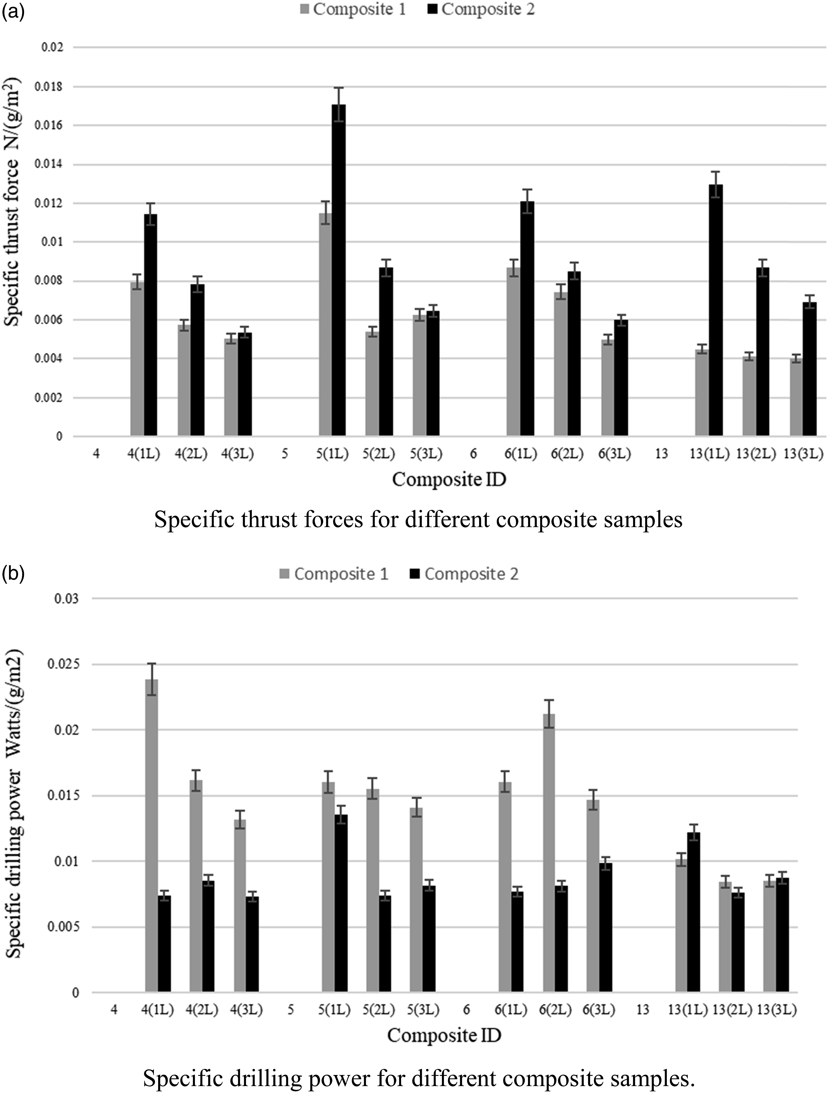
The cutting force of the warp and weft yarns before and after polymer infusion.

The cutting forces of weft yarns in the samples 4 and 13 vary due to the differences in the yarn count and the number of plies.
In the case of a multi-laminates composite made of laminate where fibers of different plies are aligned in the same direction, the thrust force should be increased to keep the same drilling speed, so higher drilling power is expected for a composite of a higher number of laminates, figure 10-(b). While Figure 11 shows the relation between the specific drilling power and thrust force for samples of different fiber volume fractions and the number of laminates, keeping the constant drilling time. It has been revealed that composite 1 of high fiber volume fraction required a higher specific thrust force, consequently, its drilling force will be higher. Specific drilling power versus specific thrust force.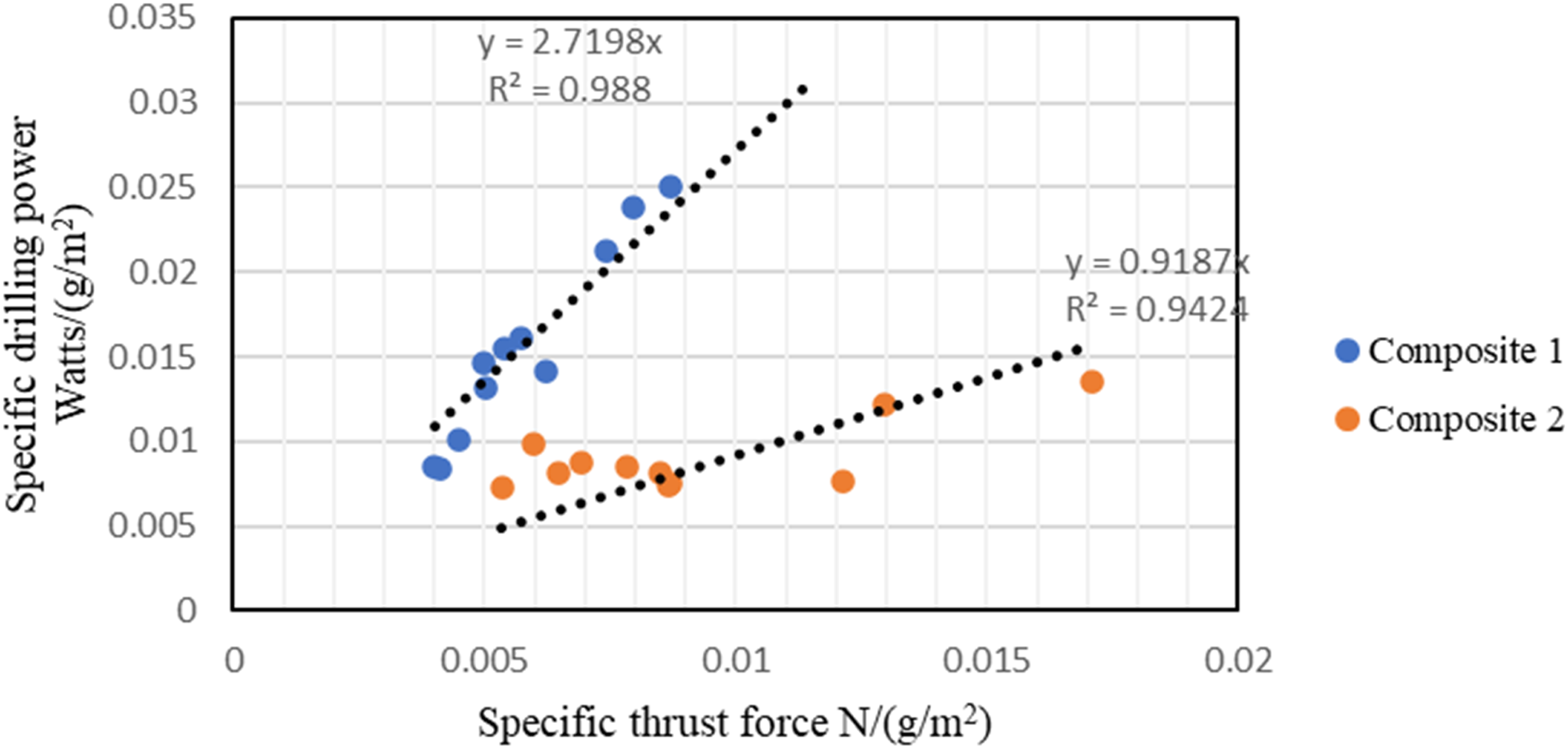
Effect of fiber volume fraction on drilling power
Figure 12 shows the relation between the specific drilling power and the fiber volume fraction, which showed its proportionality. The specific drilling power versus the fiber volume fraction of the composites.
Composites of high fiber volume fraction required higher specific thrust force, so, their drilling force will be higher, i.e., more drilling power is expected. The drill has to cut more fibers and less polymer layer.
Effect of the fabric rigidity on the drilling power
Conventional drilling of FRPC often results in a variety of damage to the composite laminates, which affects the load-bearing capacity of the composite joints, and consequently, leads to their eventual discard. 51 The damage to the hole depends on the properties of the fabric laminate used, delamination is the most critical defect as it has the highest level of impact on the accuracy and quality of a drilled hole. Delamination is simply defined as the main form of failure of laminated composites whereby the laminates or layers separate along with their interfaces. 52
Flexural rigidity of the different fabric samples.


Composite drilling power versus fabric-specific flexural rigidity.
Evaluation of quality of the fabric-reinforced polymer composite hole
The delamination makes the damage mechanisms in composite materials more complicated. In the assessment of delamination damage in drilled materials, the extent of material damage was measured, and the delamination factor has been evaluated.
54
Delamination defect was found to be related to the thrust force generated during drilling, the force for a given workpiece and material combination depends on the drill geometry and the cutting conditions. As the processes governing the drilling process in these fiber polymer composite materials are not yet fully understood.
36
The conventional delamination factor is defined as the ratio of the diameter of the delamination area to the diameter of drilled hole as equation (4) to quantify the level of delamination around the drilled hole.
55
The delamination factor increases as the laminate fabric’s flexural rigidity increases. The stiffer the laminate, the possibility of peel-up delamination increases and the lower probability of push-out delamination. Figure 14(a) shows the values of the delamination factor as a function of the total flexural rigidity of the laminate’s fabric. While the effect of the number of laminates on the delamination factor is shown in Figure 14(b). The effect of the laminates fabric’s specific flexural and the number of laminates on the delamination factor.
From the results obtained on delamination factors, it is apparent that the FRPC composite specimens have smaller values for single laminate and increased as the number of laminates increased.
To compare the effect of the fabric structure on the specific drilling power, an index, Drilling Index (DI), was introduced, which includes the specific drilling power and the cutting stress of the yarn-reinforced polymer used with the same volume fraction as in the composite. delamination factor
The value of DI was calculated for the different composites. Figure 15 shows that the drilling behavior of the different samples can be classified by their drilling index. The higher DI value of the composite means that the drilling force required to drill the hole is expected to be higher and we need a higher thrust force to create it, as in the case of the plain weave. The analysis of the effect of the fabric design on the drilling force shows that for the same repeat the number of yarn intersections in plain weave is higher than that of other designs such as twill, satin, etc. Consequently, the drilling force is expected to be higher, as shown in Figure 15. Knowing the Drilling Index of a particular composite design, then the value of the drilling process parameters of the FRPC, such as drill speed, and feed per revolution, can be chosen to guarantee high drill performance. Drilling index for different samples.
The analysis of Figure 15 shows that with the increase in the number of laminates, the value of DI increases, indicating more specific power is needed to drill the hole in a composite material. Moreover, composite No.1 has better drilling performance than composite No.2 because its fiber volume fraction is less.
Conclusion
This work presents a study of the effect of fabric structure and the number of laminates in FRPC on the drilling power and drilling thrust force, discussing the main challenges related to the drilling of fabric-reinforced polymer composite such as delamination. The thrust force and drilling power of fabric-reinforced polymer composite have been investigated. The experimental study reported that: • The relationship between the drilling power and fabric specifications was discussed theoretically and measured experimentally. Factors affecting the drilling power of the FRPC have been derived. • The plain weave fabric design needs significantly higher drilling power than the other fabric designs of the same unit repeat. • It has been revealed that the use of laminates of high fiber volume fraction required higher specific thrust force, and their drilling power will be higher. • The drilling power is proportional to the total fabric flexural rigidity and the composite fiber volume fraction. • Delamination factor analysis showed that the decrease in fabric flexural resistance causes a reduction in the delamination factor. • The increase in the number of laminates increases the probability of delamination of the composite. • It was proved that the composite-specific drilling power is proportional to its fiber volume fraction. • The developed Drilling Index can be used to calculate the expected value of the drilling power for a fabric-reinforced polymer composite. • The use of basket weave shows the highest Drilling Index than the other fabric designs.
Footnotes
Declaration of conflicting interests
The author(s) declared no potential conflicts of interest with respect to the research, authorship, and/or publication of this article.
Funding
The author(s) received no financial support for the research, authorship, and/or publication of this article.