
Abstract
The complex mechanical properties of coated fabrics make it difficult to obtain accurate constants for design and analysis. A high efficient constitutive model of coated plain-weave fabrics is proposed to realize the prediction of mechanical behaviours in arbitrary directions. The coupling mechanism between macro and meso deformation of coated fabrics is analyzed firstly, and the constitutive relation of the model is established based on mesoscopic parameters with clear physical interpretation. Then, the material property values of specimens are obtained by using a multi-objective optimization algorithm according to the experimental data. Unlike the previous constitutive relations which need to use finite element methods to get numerical solutions, the constitutive relation established in this paper can be mapped to a quartic equation with analytical solution, and the calculation efficiency can be greatly improved. The deviations of model predictions with experimental results, e. g., 0.052 (tension), 0.009 (width), 0.014 (length, warp), 0.025 (length, weft), 0.027 (angle, warp), 0.030 (angle, weft), show that the model predictions are in good agreement with the experimental data.
Introduction
The inflatable structure made of coated fabrics has the characteristics of light weight, small, strong bearing capacity, fast deployment, etc. It has been widely used in emergency safety assurance, such as inflatable aircraft evacuation slides, 1 marine evacuation system (MES),2,3 etc. Coated fabrics are fiber reinforced composite materials with quite complex mechanical behavior, such as strong geometric nonlinearity, large deformation, stress relaxation, creep characteristics, etc. The components of large inflatable structure may be as long as several meters, or even more than 10 m, and the change range of length before and after inflation can reach more than 0.5 m. The mechanical behaviours of coated fabrics used in the manufacture of inflatable products determine the geometric scale changes of the components under different internal gas pressures. The anisotropy of coated fabrics can be used to synchronize the deformation of inflatable components with different scales. For instance, the stiffness of coated fabrics is selected by cutting direction, so that two inflatable columns with same diameter/stiffness ratio but different diameters can be deformed synchronously during inflation.
The physical structure of coated fabrics determines their mechanical behavior. 4 According to different modeling methods, the constitutive models of coated fabrics can be divided into two categories: continuum models and meso-structural models.5,6
Continuum models are based on three assumptions: homogeneous, anisotropic and continuum. The stress-strain curves or response surfaces are obtained through a large amount of experiments, then mathematical expressions are established by using increments, polynomials,7,8 etc., and finally the methods such as multi-linear and response surfaces are used to establish the constitutive model to describe the macroscopic characteristics of materials, such as geometric nonlinearity,9–11 large deformation, 12 stress relaxation, 13 creep characteristics, 14 viscoelastic deformation, 15 plastic deformation, 16 etc. The advantage of continuum models is that they can be easily implemented in the commercial software, e. g., Dinh et al. 16 proposed a new constitutive relation to express the nonlinearity based on the elasto-plastic assumptions, which is implemented in ABAQUS as a user material subroutine. However, continuum models can only represent the macro mechanical properties, but cannot explain the micro mechanical behavior. The accuracy of the model is based on the test curve, and a large amount of experiments are required to use this kind of model. Moreover, the continuum model regards the material as a homogeneous continuum composed of anisotropic materials, and there are always several parameters without clear physical interpretation in its mathematical expression, so it is difficult to use a unified expression to describe the complex deformation relationship of the material. Although the calculation amount of continuum models is lower than that of meso-structural models, they still need to be simplified before engineering application.
Meso-structural models predict macro mechanical behavior based on fabric structure and deformation of coated fabrics. The internal mechanical mechanism is explained at meso level. The physical interpretation of model parameters is clear, and the description of the constitutive relation is more accurate. Researchers have established constitutive relations based on the microstructures of yarns, coatings and their interactions17–19 through the combination of mechanical concepts and mathematical analysis, and have proposed Tensioned Fabric Structures, 20 hyperelastic constitutive model, 21 micro-mesa unit cell model, 22 yarn model, 23 digital element methods24–26 and multi-layer solid elements method, 19 etc. Among the studies, Gade et al. 17 established a meso-scale model with regard to the coating stiffness, by performing an inverse process of parameter identification using Levenberg-Marquardt algorithm, and the model is implemented as a material law into a finite element program. The meso-structural models describe the constitutive relation based on the microstructure of the real coated fabric, so the prediction of its macro mechanical behavior is more accurate. Although the prediction accuracy is high, the current meso-structural models of coated fabrics are already very complicated, and the complex mathematical expressions lead to a huge workload. With further development, the meso-structural models will become more complicated, which will seriously affect their popularization and use.
At present, the research on the mechanical properties of coated fabrics lags behind conventional materials, resulting in many uncertainties in the analysis. 5 Therefore, it is necessary to establish a simple, efficient, accurate and reliable constitutive model of coated fabrics. During the development of the large inflatable structures, our research group has conducted a large number of experiments and analyses on the mechanical properties of coated fabrics. In this paper, a new model for predicting the mechanical properties of coated plain-weave fabrics in arbitrary directions is proposed, which has the following advantages: (1) The model is established based on parameters with clear physical interpretation, and the constitutive relation can be mapped to a quartic equation with analytical solution. (2) The modeling method is intuitive and easy to understand, and the model can predict the mechanical properties of coated fabrics at both macro and meso levels. (3) The key material properties of coated fabrics can be obtained by using only 3 groups of tensile test data from weft, warp, and other arbitrary directions.
It is a simple and accurate constitutive model to express the complex response under various loadings, which is suitable for the needs of engineering design and analysis, and can solve the problem of design and material selection for large inflatable structures.
Mechanism analysis of mechanical model of coated fabrics
Coated plain-weave fabrics are composite materials that cover both sides of an underlying woven structure with flexible impermeable coatings. The underlying woven structure is made of high-strength warp yarns (hereinafter single warp yarn is abbreviated as A-FB) and weft yarns (hereinafter single weft yarn is abbreviated as E-FB). The coating, as the physical protective layer for the underlying woven structure, has the characteristics of liquid sealing, gas sealing, wear resistance, corrosion resistance,
4
etc. The underlying woven structure and the coatings jointly determine the mechanical properties of coated fabrics. Coated fabrics have excellent tensile strength and shear strength. The thickness of coated fabrics used for manufacturing inflatable structures is usually within a millimeter. Each single yarn (hereinafter abbreviated as FB) is composed of multiple fibers with small diameter, and it has weak compression resistance and bending resistance. As shown in Figure 1, A-S is the section of A-FB, which can display the micro morphology of A-FB, and, E-S is the section of E-FB, which can display the micro morphology of E-FB. Macro and micro morphologies of coated fabrics.
The coated fabrics are a kind of large deformation, nonlinear and anisotropic material. Its ultimate tensile strain can reach more than 0.5. Its nonlinearity is represented by the significant nonlinearity of the mechanical behaviours at macro level, and at micro level, the tension distribution in E-FB, A-FB and the coating changes dynamically due to the change of weaving angles. Its anisotropy shows that there is obvious variation in the mechanical behaviours in different tensile directions at macro level, and the variation law of weaving angles in different tensile directions is also different at micro level. Generally, A-FB and E-FB are made of the same materials, but the mechanical behaviours curves in the warp and weft directions are different due to the difference in the quantity of fibers within A-FB and E-FB, density (the amount of A-FB and E-FB per unit width) and the weaving undulations.
As shown in Figure 2, if a coated fabric specimen is tensed in the Y direction, it will become longer in the Y direction and shorter in the X direction perpendicular to Y. Since the coating on its surface has certain compressive resistance in the X direction, even if the deformation reaches the limit and fracture occurs, the width of the specimen in the X direction will not tend to zero. Tensile deformation of a coated fabric specimen.
It can be seen from Figure 2 that there are three cross-sections which can establish constitutive relations, namely, X-S, A-S and E-S. The force is transferred in tension shear coupling at A-S and E-S sections. Shear is the dominative deformation mode for woven fabrics in forming. In order to avoid shear analysis and simplify the constitutive relation, X-S section is selected to establish the constitutive relation, and the shear deformation 27 can be equivalent to compressive deformation. Since the tension stiffness of the coating is much smaller than that of FB, it can be added onto FB. In the balance state, the tension is transferred through A-FB and E-FB on the X-S section, and the components of A-FB and E-FB in the X direction are balanced with rebound force of the coating. The deformation of the specimen in the X direction consists of two parts: (1) the deformation driven by the Poisson’s effect of the coating; (2) the deformation driven by the tension component of FB in the X direction. During the deformation of the specimen, the weaving angles change dynamically, leading to the dynamic change of the number of A-FB and E-FB crossing X-S section, as shown in Figure 2. The proposed model in this paper contains four key indexes of material parameter: tension stiffness of A-FB, tension stiffness of E-FB, Poisson ratio and compressive stiffness of the coating, and the physical interpretation of each parameter is clear.
Membrane materials are always in biaxial stress state, but it is difficult to achieve perfect biaxial stress failure in the laboratory. 5 In design specifications, a reduction factor is always used to reflect the relationship between biaxial tensile strength and uniaxial tensile strength. Uniaxial tension methods are widely used and recommended in design specifications. In this paper, the constitutive relation of the model will be established based on uniaxial tensile methods. Generally, the design of civil engineering focuses on the prediction of the damage of coated fabrics caused by the ultimate tension. 28 However, the gas-sealing of coated fabrics also needs to be considered in the design of inflatable structures. Tiny gaps will appear in the coating under the condition of large deformation, resulting in gas leakage. Therefore, the model established in this paper does not consider the ultimate damage, and its predetermined working range is 0–2/3 ultimate tension.
Establishment of the constitutive relation of coated fabrics
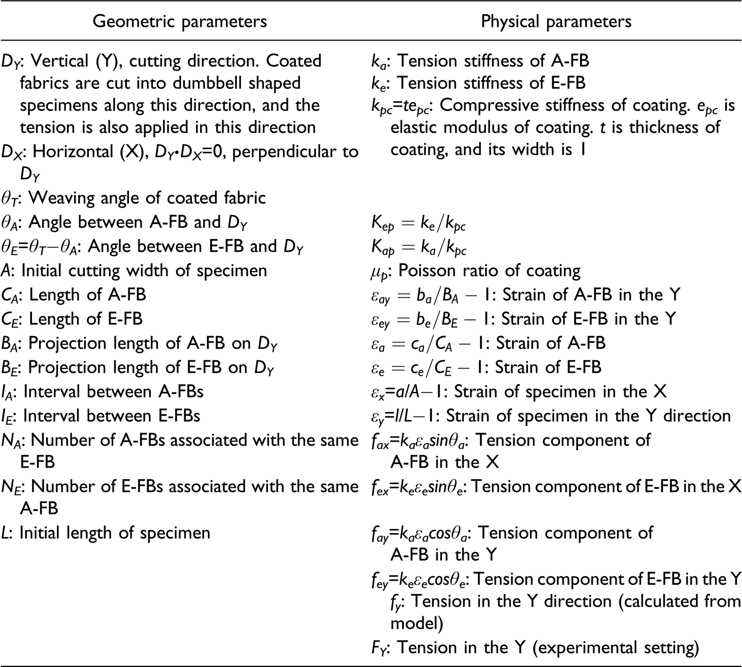
Definition of geometric and physical parameters of the model
θ
T
, θ
A
, θ
E
, A, C
A
, C
E
, B
A
, B
E
, L are geometric parameters related to the initial state of a specimen, all of which are in the measurement area. θ
T
, I
A
, I
E
are geometric properties of coated fabrics, and their values can be directly measured by microscope. D
Y
, A, L are geometric parameters of a specimen, and their values are determined by the contour design of the specimen. After the design of the specimen, θ
A
, θ
E
, C
A
, C
E
, B
A
, B
E
can be obtained by geometric measurement of the specimen or trigonometric function calculation with D
Y
, A, L as input. Under the action of tension in the D
Y
direction, the geometry of the specimen will change and the above parameters will change to θ
t
, θ
a
, θ
e
, a, c
a
, c
e
, b
a
, b
e
, l. The geometric description of these parameters is shown in Figure 3. Definition of geometric parameters of coated fabrics and the comparison between before and after deformation.
It can be seen from Figure 3 that the widths of E-FB and A-FB in the X direction are always consistent during uniaxial tension of coated fabric specimen, which is the basis to solve the geometric deformation of E-FB and A-FB. k a , k e , k pc , μ p are inherent material properties of coated fabrics, and their values can be obtained by performing an inverse process of parameter identification using a multi-objective optimization algorithm. 29 The others are process parameters.
Establishment of constitutive relation
The constitutive relation of coated fabrics is established based on the following 3 assumptions: (1) The specimen has no constraint in the X direction and can deform freely, ignoring the influence of fixture. (2) Deformation and tension are in the same plane, each E-FB or A-FB in the measurement area of a specimen has exactly the same geometric and physical state, and E-FB or A-FB always keeps a straight line during deformation. (3) During the test, the specimen is kept in a non-destructive state without irreversible material damage such as fiber pull out.
The above assumptions are analyzed as follows: (1) Dumbbell shaped specimens should be prepared according to GB/T 528-2009 standard, and a transition zone shall be formed between the two ends of the measurement area to eliminate the constraint of the X-direction deformation. (2) Since the coated fabrics are very thin, usually within 1 mm, which is far less than the length and width of the specimen, it belongs to a plane stress problem. Ignoring the occasional defects in the processing of coated fabrics, it is considered that all the E-FBs or A-FBs in the specimen are completely the same and in a straight line state. (3) The maximum tension of coated fabrics used for inflatable structures shall be lower than the value that creates sealing damage. The sealing damage occurs before the structural damage. This model is applicable to the stage with good gas tightness, ignoring the irreversible material damage.
Under the above assumptions, the accidental factors in the manufacturing and testing process that impact the model accuracy can be ignored.
When θ A ≠0 and θ A ≠θ T , under the action of F Y , the width of the specimen will change from A to a, and then ε x =ε μ +ε s , in which ε μ represents the strain due to the influence of Poisson’s ratio and ε s represents the strain due to coating compression by tension component of FB in the X direction.
Taking E-FB passing through X-S section as an example for deformation analysis, formula (1) can be obtained.

Since

Let

As shown in Figure 3, a, b
e
, c
e
form a right triangle and satisfy Pythagorean theorem (formula (4)).

Substitute formula (3) into formula (4) to eliminate c
e
, then formula (5) can be obtained.

Formula (5) is a quartic equation about b
e
, in which 5 coefficients are known. b
e
can be solved directly by “Ferrari” or “adjoint matrix of polynomial”. Then, c
e
can be solved by substituting b
e
into formula (3). b
a
and c
a
can be solved similarly. When θ
A
≠0 and θ
A
≠θ
T
, due to the influence of coating stabilization and friction between FBs, the tension is transferred in the coated fabrics in a tension-shear coupling manner (Figure 2, sections A-S, E-S). ε
y
is determined by b
e
and b
a
, and its mathematical expression is as formula (6).

Formula (6) corresponds to the mechanical behaviours when θ A ≠0 and θ A ≠θ T . There is no E-FB or A-FB through both ends of the specimen, and the tension needs to be transmitted in alternating between E-FB and A-FB. Therefore, the deformation is composed of the deformations of E-FB and A-FB.
As shown in Figure 2, under the action of F
Y
, the specimen may lengthen in the Y direction and shorten in the X direction, resulting in the changes of the number of E-FBs (n
e
) and the number of A-FBs (n
a
) passing through X-S section. It can be seen from Figure 4 that θ
a
and θ
e
determine n
e
and n
a
. Taking the calculation of n
e
as an example, Schematic diagram of solving the number of warp and weft yarns passing through arbitrary X-S section.


Divide both ends of formula (8) by c
e
, and substitute a/c
e
=sinθ
e
, then get formula (9).

Substitute formula (9) into formula (7), and calculate n
e
by formula (10).

Similarly, calculate n
a
by formula (11).

Then the tension in the Y direction (f
y
) can be calculated by formula (12).

All the variables (ε a , n a , θ a , ε e , n e , θ e , ε y ) are functions of a. For each given value of a, the corresponding ε x , ε y , f y can be calculated. So far, the constitutive relation of coated fabrics in arbitrary directions (D Y ) has been established.
The following is about the identification of the property values of the specimen material (coated fabrics): k a , k e , k pc , μ p .
Identification of property values of coated fabrics
According to formulas (1)–(6), μ p , K ap , K ep , ε x →ε y , ε a , ε e , θ a , θ e , which is called geometric transformation (G-T) of coated fabrics. According to formula (12), ε a , ε e , θ a , θ e , k a , k e →f y , which is called mechanical transformation (F-T) of coated fabrics. Since (G-T) → (F-T), the values of material properties μ p , K ap , K ep need to be determined firstly.
The coating is relative thin, and ε
x
is mainly from ε
s
, ε
μ
≪ε
s
, leading to a relative small μ
p
. Let k
a
=kA−FB+k
pca
and k
e
=kE−FB+k
pce
, in which kA−FB and kE−FB represent the tension stiffnesses of A-FB and E-FB, respectively, k
pca
and k
pce
represent the tension stiffnesses of the coatings on A-FB and E-FB, respectively. In order to simplify the model, k
a
and k
e
are used to describe the tensile properties of A-FB and E-FB in the subsequent analysis.
When ε
a
or ε
e
reaches a certain threshold, FB shows yield characteristics. Define the yield adjustment function of E-FB as
The conventional constitutive relation is usually solved by numerical method, while the constitutive relation established in this paper can directly obtain the analytic solution and has high calculation efficiency, making it possible to find the material property values of the specimen in a wide range and with high precision. Therefore, the acquisition of key material property values of the specimen can be transformed into the solution of the classical multi-objective optimization problem.29–31 For the seven dimensions of f
y
, θ
a
, θ
e
, a, c
a
, c
e
, ε
y
, the objective is to minimize their deviations between the experimental data and the calculated results from this relation to find the optimal k
a
, k
e
, k
pc
, μ
p
and α
a
, ε
sa
, α
e
, ε
se
. The acquisition algorithm for key material property values consists of the following three stages. (1) According to the G-T relation, constrained by the geometric deviations of all the 6 dimensions (θ
a
, θ
e
, c
a
, c
e
, ε
x
, ε
y
) less than the threshold β
G
, narrow intervals of μ
p
, k
e
/k
pc
, ck
a
/k
p
. (2) Based on (1), according to the F-T relation, constrained by the deviation of f
y
less than the threshold β
F
, obtain several groups of candidate vectors (μ
p
, k
pc
, k
a
, k
e
, α
a
, ε
sa
, α
e
, ε
se
). (3) Set a certain range of floating interval for μ
p
, k
pc
, k
a
, k
e
, α
a
, ε
sa
, α
e
, ε
se
, target minimum weighted deviation of seven dimensions (θ
a
, θ
e
, c
a
, c
e
, ε
x
, ε
y
, f
y
) to obtain the optimal combination of μ
p
, k
pc
, k
a
, α
a
, ε
sa
, k
e
, α
e
, ε
se
.
In this paper, the MCTA algorithm proposed in the literature 29 is used to calculate the key material property values of coated fabrics.
Experiment and verification
Experimental specimens and conditions
In order to verify the correctness and effectiveness of the constitutive model of coated fabrics under uniaxial tensile loads in arbitrary directions, 7 specimens are prepared according to GB/T 528-2009 standard. The coated fabrics (TPU840-060, thickness: ca. 0.60 mm) have plain-weave nylon 66 textile (thickeness: ca. 0.30 mm) as the substrate and polyurethane coating (thickness: ca. 0.15 mm) on both sides by thermoplastic method to realize gas sealing and substrate protection. The membrane material is uniform for all the 7 specimens only with different cutting directions. Taking the E-FB direction as the reference datum, the cutting angles of the specimens are 0 (weft direction), 15, 29, 44, 59, 73 and 88 (warp direction), marked as TS00, TS15, TS29, TS44, TS59, TS73, TS88, respectively. The effective measurement area is 30 mm × 230 mm (Figure 5(a)), tested on STM3000 tensile testing machine, as displayed in Figure 5(b). In order to simulate the tensile deformation during inflation, the tensile speed of 90 mm/min is selected. The coated fabrics, as polymer composite material, have obvious stress relaxation, creep and other complex characteristics, and the change rate gradually decreases with time. In order to predict the elongation of the inflatable component in the stable state, it is measured after the tension keeps constant for 10 min, and the complex effects such as stress relaxation and creep which tend to be basically stable are added onto the stiffness of FB. Considering the low inflation and deflation frequency of MES, the experiment adopts single loading, and the time interval between two tests of the same specimen is more than 120 min, so as to eliminate the residual effects of the previous tests as much as possible. Under the working condition, the tension of membrane material of MES is between 200 and 300 N/30 mm, and the gas tightness of the membrane may be reduced significantly when it exceeds 500 N/30 mm. The test range is set as 25–600 N to cover the underload and overload working range of MES. Each specimen was tested for 14 times under different tension conditions in the test range, and 7 physical and geometric quantities (f
y
, θ
a
, θ
e
, a, c
a
, c
e
, ε
y
) were recorded in each test. (a) Specimens with effective measurement area of 30 mm × 230 mm and (b) uniaxial tensile test.
In theory, the key material properties of a specimen can be obtained by using 3 groups of test data from TS00, TS88 and any other specimen. In practice, 4 groups of test data (TS00, TS29, TS73, TS88) are input into the model to improve the stability of prediction. The obtained key material parameters are μ p =0.05, k pc =15.02 (N), k a =74.3 (N), k e =115.6 (N), α a =1, ε sa =0.21, α e =9, ε se =0.12. Since ε x ↔f y is adopted to describe the constitutive relation and ε y →f y cannot be obtained directly, PID (Proportional Integral Derivative) method is first used to get ε x corresponding to ε y after only a few iterations, and then ε y →f y is obtained. The subsequent comparative analysis of model output data and experimental data is based on the same ε y .
Relative deviation between model output data (oj,k
i
) and experimental data (tj,k
i
) is
Experimental data analysis
Macro analysis
If the black box is used to shield the mesoscopic structure of the coated fabrics, and the specimen is regarded as a homogeneous anisotropic body, the macroscopic mechanical characteristics can be manifested as deformation-tension and deformation-width relationships. The comparison between the prediction curves output by the model and the experimental data is shown in Figures 6(a) and (b). The comparison between the model curves and the experimental data for (a) ε
y
↔f
y
; (b) ε
y
↔a; (c) ε
y
↔c; (d) ε
y
↔θ.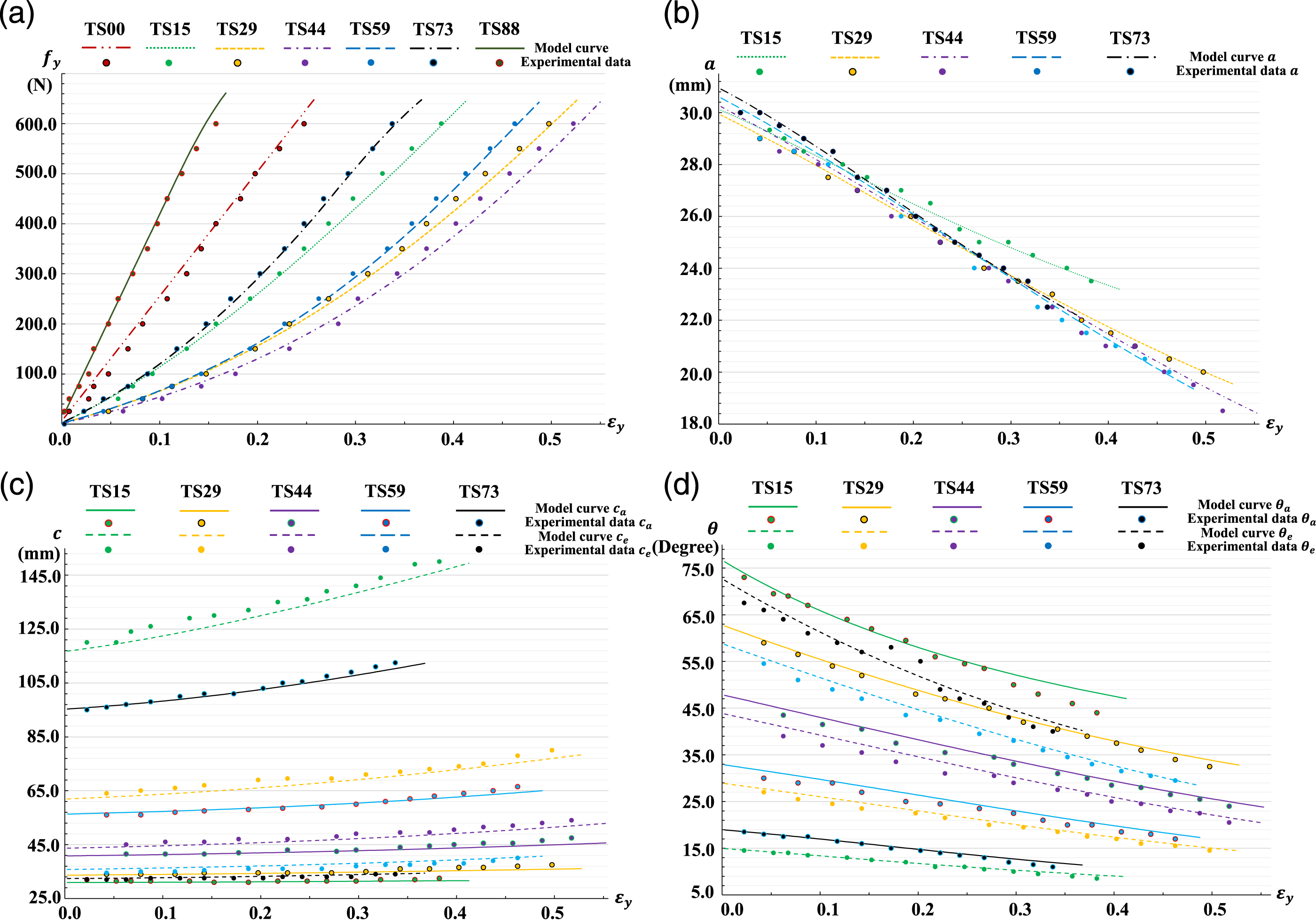
It can be seen fromFigures 6(a) and (b) that the change trend of model curves (ε
y
↔f
y
, ε
y
↔a) is consistent with that of the experimental results, and the model data is in good agreement with the experimental data. The deviation analysis results (
As shown in Figure 6(a), the value of
Meso analysis
If the black box shielding is removed, the mechanical behaviours of the coated fabrics can be presented as the change of c and θ at meso level. The comparisons between the model curves and the experimental data for ε y ↔c, ε y ↔θ are shown in Figures 6(c) and (d), respectively.
Since both ends of the FBs of TS00 and TS88 are clamped by the fixture, the morphological change of FBs is consistent with ε
y
, which belongs to constraint deformation at both ends. The deformation state of the 2 specimens is simple (only length changes), so the detailed analysis is not required. For the other 5 specimens, only a small amount of FBs (located at the end of the measurement area) is restrained by the fixture at one end and the other end is free, and most of FBs with two free ends have complex mesoscopic morphological changes (length changes and deflection occurs). The change law of the morphology of FBs can be revealed by our constitutive model. It is observed from Figures 6(c) and (d) that the change trend of model curves (ε
y
↔c, ε
y
↔θ) is highly consistent with that of the experimental results. The deviation analysis results (
Additionally, as shown in Figures 6(c) and (d), in order to adapt to the increase of ε
y
, for TS15 and TS29, the morphological change of E-FBs is due to mainly c
e
supplemented by θ
e
, and the change of A-FBs is due to mainly θ
a
supplemented by c
a
, which is opposite for TS73 and TS59, while the influence of θ and c is balanced for TS44. This indicates that D
Y
has a great impact on the mesoscopic geometry of the coated fabrics. The above phenomena can be explained geometrically as follows: ∆θ→ε
x
θ
, ε
y
θ
, ∆c→ε
x
c
, ε
y
c
, ε
x
=ε
x
θ
+ε
x
c
, ε
y
=ε
y
θ
+ε
y
c
, ε
x
θ
=∆θcosθ, ε
y
θ
=−∆θsinθ. When θ>π/4→ε
y
θ
>ε
x
θ
, for any ∆a, there is ∆θ, let
Analysis of model deviation and solution efficiency
Deviation analysis of the constitutive model.
The total deviation of the model (d =0.026) can be obtained from Table 1, indicating that the model data match well with the experimental results on the whole. The deviation of each specimen is dTS00 = 0.066, dTS15 = 0.023, dTS29 = 0.022, dTS44 =0.033, dTS59 = 0.026, dTS73 = 0.021, dTS88 = 0.070. Since the data of TS29 and TS73 are input as the model parameter, their matching degrees are slightly better than those of TS15, TS44 and TS59. The small deformation range of dTS00 and dTS88 due to no change of their weaving angles, results in their higher sensitivity of mechanical behaviours than other specimens, therefore, a greater relative deviation will be produced under the same measurement noise.
It can be seen from the column chart in Table 1 that the maximum value of d
j
is
The deviation analysis shows that the model proposed in this paper can accurately describe the mechanical behaviours of coated fabrics, and the prediction accuracy can meet the needs of large inflatable structure in the engineering application. The model can not only describe the macroscopic mechanical properties of the coated fabrics, but also explain the geometric and mechanical mechanism at meso level, which can provide inspiration for material design. Moreover, the model has high calculation efficiency, and the single calculation time for ε x ↔f y is 2.4×10⁻⁵ seconds. The calculation efficiency of ε y ↔f y depends on PID adjustment accuracy of ε x ↔ε y . When the accuracy is less than 1×10⁻⁴, the single calculation time for ε y ↔f y is ca. 5×10⁻⁴ seconds. The high calculation efficiency of the model will facilitate large-scale engineering analysis.
Conclusion
A novel constitutive model of coated plain-weave fabrics under uniaxial tensile loads is established in this paper. This model can not only describe the macroscopic mechanical properties of the coated fabrics, but also the mesoscopic changes of FBs and weaving angles. Only four key material parameters with clear physical interpretation are needed for this model, and the constitutive relation can be mapped to a quartic equation with analytic solution, which has extremely high efficiency. The experimental data show that the model can well predict the mechanical behaviours and internal geometric changes of the coated fabrics. If the characteristics of fibers (FB composition) are considered, the model will have the ability of microscopic description. If viscoelasticity, relaxation, creep and other factors of FB are considered, the model can more accurately describe the complex mechanical properties of coated fabrics. The geometric and physical interpretation of the constitutive relation of this model is intuitive and clear, which is easier for engineers and technicians to understand and apply than the complex mathematical description methods such as tensor and partial differential equation. Due to the extremely fast solution speed of the constitutive relation, it can support large-scale engineering structure performance analysis and optimization, and can solve the deformation simulation problem of large inflatable structures, which has good engineering application potential.
Footnotes
Declaration of conflicting interests
The author(s) declared no potential conflicts of interest with respect to the research, authorship, and/or publication of this article.
Funding
The author(s) disclosed receipt of the following financial support for the research, authorship, and/or publication of this article: This work was supported by the National Key R&D Program of China (grant number 2022YFC3006004); the Ministry of Industry and Information Technology High tech Ship Project (grant number MC-201902-C01); and the National Natural Science Foundation of China (grant number 51305052).