
Abstract
Conventional machining of composite material was challenging due to delamination, tool wear, fiber pull-out, spalling, fiber fraying, heat generation, and excessive stresses. The non-conventional machining process was preferred for high-strength materials to produce complicated shapes with a better surface finish. This research describes an experimental analysis of abrasive water jet machining (AWJM) on flax/wire mesh/hemp reinforced epoxy composite. In addition, recycling of waste carbon fiber composite (WCFC) was also practiced and reused as a filler particle along with the fabricated hybrid composite. The hybrid composite was fabricated using the hand layup technique with 20.3 wt% of fiber, 10.5 wt% of wire mesh, and 2 wt% of WCFC. Experiments were conducted to evaluate the influence of standoff distance, traverse speed, and abrasive mass flow rate on the output responses such as kerf angle (θ) and surface roughness (Ra). The design of experiments found that surface finish was improved with optimum process parameters. It was detected that spalling defects, wear track, and micro-cutting were noteworthy in the machined hybrid composite concerning high standoff distance and abrasive mass flow rate. Morphological study in the cut surface of the hybrid composite was analyzed through a scanning electron microscope (SEM), and the fiber characterization was done through Fourier-transform infrared spectroscopy (FTIR).
Keywords
Introduction
Natural fiber composite materials were used in lightweight engineering applications like automobile, aviation, marine, defense, and sports due to their high strength, wear resistance, thermal insulation, and stiffness. The natural fibers extracted from plants consist of cellulose as their main structural element, whereas the fiber obtained from animals contains protein. 1 Generally, the natural fibers with a higher percentage of cellulose content were used to fabricate lightweight composite materials. Therefore, flax and hemp fiber offer a wide range of automobile applications. 2 The composite fabricated with hybrid fibers poses a more significant advantage than mono fiber-reinforced composite. 3 Generally, composite materials were strengthened by reinforcing long continuous fiber, wire mesh, and particles. The conventional machining of wire mesh composite material was challenging because of improper dimensional accuracy, fiber pull-out, spalling, and delamination. 4 Hence, abrasive water jet machining (AWJM) was practiced as a non-contact process to overcome conventional machining limitations.
Many investigators researched the effect of process control on the composite materials machined by AWJM. Dhanawade and Kumar 5 studied the delamination effect and kerf geometry of carbon fiber composite machined by AWJM. Response surface methodology (RSM) was used as a statistical design approach in the study. The authors conclude that the delamination factor decreases by increasing the abrasive mass flow rate and water pressure. Patel and Shaikh 6 estimated the roughness and kerf angle of the banana fiber epoxy composite while machining with the help of AWJM. They found that the most prompting parameter influencing the output response was traverse speed and standoff distance. Dhakal et al. 7 executed AWJM on three composites: carbon fiber, flax fiber, and hybrid flax/carbon fiber composite. The authors concluded that hybrid flax/carbon composite poses higher damage due to more significant standoff distance and weak interfacial bonding. Prabu et al. 8 investigated the process parameter of AWJM on the fabricated banana fiber polyester composite. The authors studied the dimensional accuracy of the machined surface by varying the input parameters like standoff distance (SOD), traverse speed (TS), and water pressure. As a result, it was concluded that standoff distance affects surface roughness by 60.63% and kerf width by 74.80%.
The studies on wire mesh reinforced epoxy composites were previously reported by numerous authors and were well known for their mechanical properties. Uzay et al. 9 studied the effect of stainless steel (SS) wire mesh incorporated carbon fiber/epoxy composite. The author reported that reinforcing wire mesh in-between the carbon fibers significantly improves the flexural stiffness of the sandwich panel by 3.88 times that of the parent composite. Krishnasamy et al. 10 performed vibrationally and wear characteristics of wire mesh reinforced aloe vera/flax/hemp fiber epoxy composite. Both impact and wear resistance characteristics of wire mesh/BaSO4 incorporated composite were increased by 18.7% and 22.3%, respectively. Dani and Venkateshwaran 11 investigated the impact and fatigue behavior of glass fiber epoxy composite reinforced with brass wire and nano-silica particles, a reasonably new hybrid composite. The authors confirmed that reinforcing brass wire mesh in-between woven glass fibers improves the fracture toughness by 23.6% and improves the fatigue life cycle count from 31 × 103 to 37 × 103. Brass wire and nano-silica particles provide excellent penetration resistance and reduce micro-crack propagation.
In the last 15 years, numerous studies have described different recovery methods to recycle the end-of-life or waste carbon fiber composite (WCFC) materials for value-added applications. 12 Recycling WCFC prevails a challenging task due to covalent bonding and polymer intermolecular cross-linking chain in the matrix. 13 Thermal, chemical, and mechanical recycling were the major recycling technologies summarized by most research in detail with environmental aspects. 14 Giorgini et al. 15 investigated the fiber extracting pyrolysis process from 70 kg scraped WCFC. The thermal decomposition of WCFC was performed in an inert gas medium at 500–600°C. As a result, the authors found that 20% of oil waste, 40% of gaseous waste, and 40% of char residue were obtained with recovered carbon fiber. In order to obtain good quality carbon fiber without char, a new process such as a superheated stream at 550°C was carried out in the post pyrolysis method. 16 Liu et al. 17 recovered 85% carbon fiber from WCFC by immersing the composite for 70 min in the chemical composition of potassium hydroxide (KOH), phenol, and water at an optimum of 1 g/10 g/100 mL. The recovered carbon fiber from solvolysis performance was 23% lesser than virgin carbon fiber and had poor adhesion with the polymeric resin. 18
Based on the above literature review, the research gap for the present study was identified. This research relates to stainless steel (SS) wire mesh incorporated hemp/flax epoxy composite. Mechanical recycling of WCFC particles requires less energy than the other techniques; hence WCFC was crushed and reused as particulate in the composite fabrication process. The novelty of this work was to reduce environmental pollution and global warming by recycling WCFC without consuming more energy. However, no previous research has been described on machining the wire mesh reinforced hybrid composite using AWJM to achieve a good surface finish. Thus, the uniqueness of the present research work was to achieve appropriate machining parameters for the operative output parameters.
Experimental methods and materials
Materials
The stainless steel (SS) wire mesh containing chromium 18%, nickel 8%, carbon 0.08%, and iron were used to fabricate the hybrid composite. The WCFC was segregated from revamping work done in Katpadi rail over the bridge, Vellore. Figure 1 shows the waste or scrap WCFC collected from bridge renovation work. Woven hemp and flax fibers were bought from Chennai SM composite. The binder epoxy (LY556) and hardener (HY951) were supplied from Herenba instruments & engineers, Chennai. Katpadi rail over bridge strengthen by woven carbon fiber and waste carbon fiber composite (WCFC).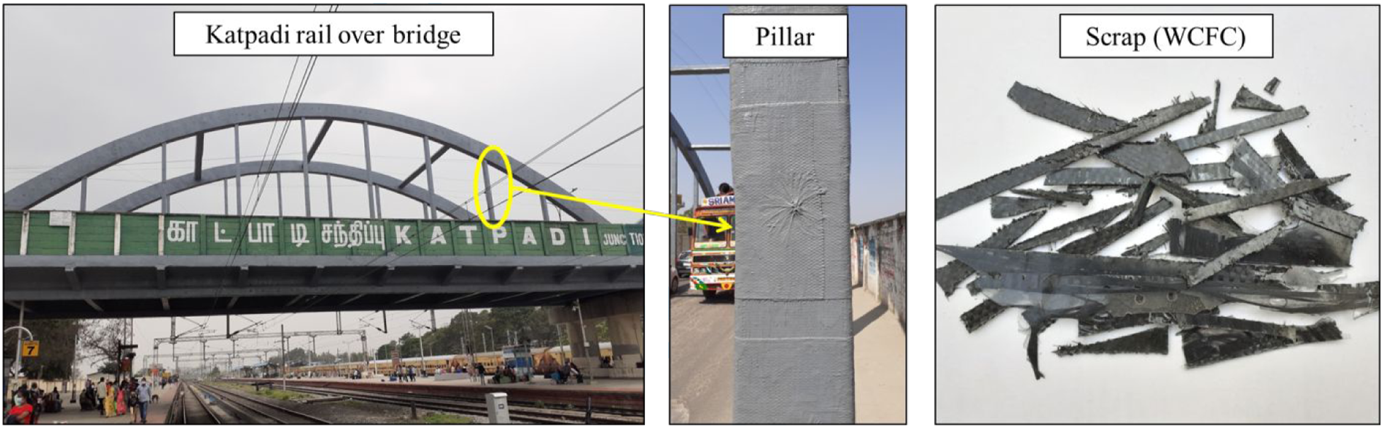
Surface treatment
The alkaline treatment for woven hemp and flax fibers was done with 5% concentrated sodium hydroxide (NaOH) for 2 hr as per standard ASTM D1695-07 (2019). Later, the woven fibers were detached from the acidic fluid and washed numerous times with distilled water until the pH reached. 7 The dried-off woven fibers were kept in a hot air oven at 110°C for 30 minutes (BST/HAO-1124).
Characterization
The machined surface and WCFC particles were captured with the scanning electron microscope (Zeiss EVO18) as a part of the morphological study. The specimens and particles were coated with gold (Au) and palladium (Pd) conductive material by using sputter coater apparatus (Quorum-SC7620) with a thickness of 0.05–0.1 mm. Nearly a 9.12e-7 mbar vacuum was maintained inside the SEM instrument to eradicate unwanted charging effects.
Fourier-transform infrared spectroscopy (FTIR) was a powerful technique to distinguish organic, inorganic, and polymer materials. The FTIR (IRAffinity-1; SHIMADZU, Japan) spectrum was described by a KBr beam splitter, and the wavenumber was recorded between 4000 to 400 cm−1. In infrared spectroscopy, IR radiation was passed through the samples to find their functional groups.
Fabrication
In the previous research work,
19
the composite with 2% of WCFC particles (300 μm) provides improved mechanical, vibrational, and tribological properties,
20
whereas 3% WCFC incorporated composite possesses lower mechanical strength than other techniques. Hence, the crushed 2% WCFC particles were initially dispersed in the estimated epoxy resin and stirred up for 5 min using a mechanical stirrer at 1000 rpm. The hardener was added to the mixture and agitated for the next 2 min. The WCFC dispersed epoxy was generously layered over the bottom mold plate, followed by woven hemp fiber, 30° orientation wire mesh, and flax fiber one over the other, as shown in Figure 2. During the hand layup process, the entrapped voids were exiled by roller, and the extra resin was wiped manually. The fabricated 3 ± 0.4 mm thickness hybrid composite was dried at room temperature for the next 24 hours. The earlier literature study carefully chose the configuration, curing kinetics, and fiber/epoxy weight percentage. (a) Stacking sequence (b) Cut section of fabricated composite.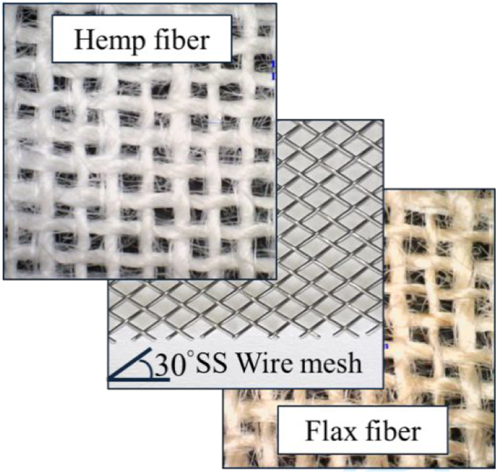
Experimental details
The computer-controlled flying arm AWJM setup was used for machining the fabricated hybrid composite. The AWJM machine has abrasive metering and an automatic feeding system. The nozzle assemblage comprises of 0.76 mm diameter nozzle with an orifice diameter of 0.25 mm. The entire experiment was conducted with a garnet abrasive particle of 177 μm (mesh size #80), as shown in Figure 3, and a water pressure of 300 MPa was maintained. The abrasive water jet machining and its parts are shown in Figure 4. Typical size and shape of garnet utilized in the machining process. Photographic image of abrasive water jet machine and it’s parts.

The essential output parameter in AWJM was surface roughness (Ra) and kerf angle (θ). The surface profilometer (MFW 250) instrument was used to find the surface roughness value of the machined surface. The probe traversing speed and sampling length was set to 0.25 mm/s and 5 mm, respectively. The kerf width and thickness of the cut sectional area were measured using a dino-lite edge microscope (AM4115T).
The process parameter with alpha and center point.

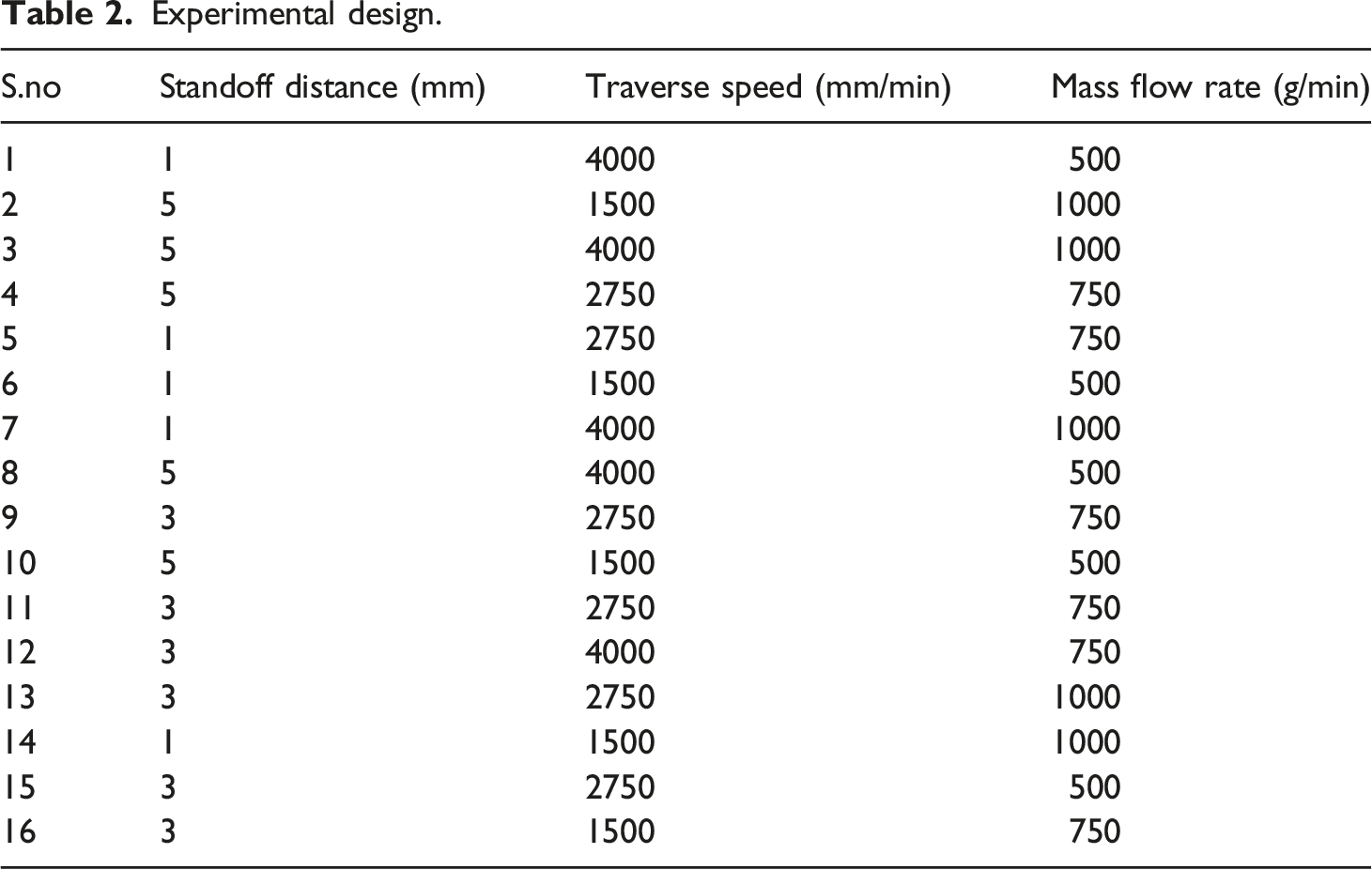
Experimental design.
The schematic of the AWJ machining nozzle assemblage is shown in Figure 5(a). After machining the composite plate, the kerf angle was calculated by measuring the specimen’s top kerf width (wt) and bottom width (wb), as shown in Figure 5(b). Equation (1) was used to calculate the kerf angle of the machined specimen. (a) AWJM nozzle assemblage (b) Kerf dimensions.

Result and discussion
The results were analyzed according to the usual technique recommended by response surface methodology (RSM) through design expert V13 software, especially for designing an experiment. After measuring the surface roughness of the machined composite, the ANOVA technique was performed to examine the consequence of controlling factors.
Characterization of WCFC and fiber
SEM analysis
The WCFC particles were analyzed by Scanning electron microscopy and found that the particles were in three different forms. They were fine recyclates (high resin content), short carbon fibers, and coarse recyclates (high fiber content),
22
which are typically shown in Figure 6. The composite matrix and natural fiber bundle was strengthened by short carbon fibers (16–526 μm), whereas the coarse and fine recyclates strengthened the matrix. SEM image of WCFC particle.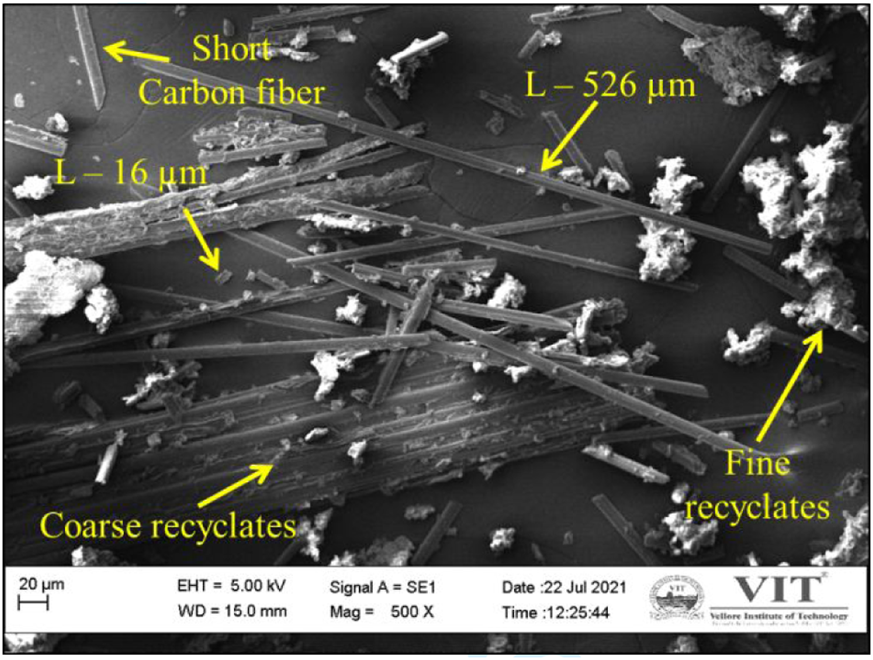
FTIR analysis
The FTIR analysis involves the adoption, emission, and reflection of light to obtain the functional compounds of the fiber. From Figure 7, it was clear that the peak at 3334.92 cm−1 (hemp) and 3319.49 cm−1 (flax) relates to the hydroxyl group (–OH) stretching vibration of the hemp and flax fiber in the cross-linked hemicellulose arrangement.
23
The Hydroxyl group in the hemp and flax fiber was responsible for the chemical reaction when the fiber was treated with NaOH solution.
24
The following two peaks at 2918.30 cm−1 (hemp) and 2920.23 cm−1 (flax) reveal the carbon-hydrogen bond (–CH) stretching vibration
25
of cellulose and hemicellulose components. The assessable peaks at 1637.56 cm−1 (hemp) and 1635.64 cm−1 (flax) were associated with symmetrical aldehyde group (–CHO) stretching vibration, which betrays the presence of the lignin element. The visible peak at 1028.06 cm−1 in both the fibers refers to carbon-carbon bond (C=C) stretching vibration manifesting the presence of wax element in the fibers.
26
FTIR spectra of (a) Hemp fiber and (b) Flax fiber.
Surface roughness
The fabricated composite’s surface roughness (Ra) after AWJ machining with variable input parameters was shown as the 3D surface plot in Figures 8(a) and (b). The surface roughness of the machined area increases concerning the incremental value of traverse speed and standoff distance.
27
It was realized that transverse speed (TS) was the significant factor, whereas else abrasive mass flow rate (AMF) and standoff distance (SOD) were the most significant factors which control the surface roughness value. The rise in AMF rate and SOD increases the spalling delamination in the exit area of the composite. When the abrasive mass flow rate increases, the bonding between wire mesh and epoxy interface diminishes. The increase in standoff distance offers divergence of water and abrasives at a higher range, increasing the adjacent sprinkling of the garnet particles.
28
The jet divergence decreases the kinetic energy and deceptively cutting ability. Thus the interaction zone produces a poor surface finish along the machined surface area. 3D surface plot showing RSM results.
From Figure 8(a), a gradual decrement of Ra had been achieved from 500 to 750 g/min while considering mass flow rate alone. Furthermore, the Ra seems to be uphill when the AMF increases from 750 to 1000 g/min. At 1500 mm/min, the complete interaction of garnet particles was involved due to the suitable machining process parameter. However, as the traverse speed was increased to 4000 mm/min, the inadequate time for cutting caused tears on the lateral surface of the composite. A maximum of 15.4 μm was witnessed at 5 mm of SOD and 1000 g/min of AMF.
In AWJM, kinetic energy played a significant role in Ra variation and was influenced by input process parameters. The overall experimental result specifies that the traverse speed and standoff distance were directly proportional to surface roughness. An increase in traverse speed leads to minor garnet particle impingement and raises the lateral region’s roughness. This statement was similar to the research work reported by Azmir et al. 29 and Dhanawade et al. 30 performed AWJM on natural fiber composite and graphite-epoxy composite, respectively. From Figure 8b, it was clear that standoff distance at 1 mm and mass flow rate of 750 g/min was the optimal parameter to be considered to achieve good surface roughness for the constant water pressure. Further, the ANOVA technique was executed to find the influence of every input parameter on surface roughness.
Therefore, the final equation for surface roughness (SR) in terms of a coded factor was shown in equation (2)
Table 3 ANOVA for surface roughness.

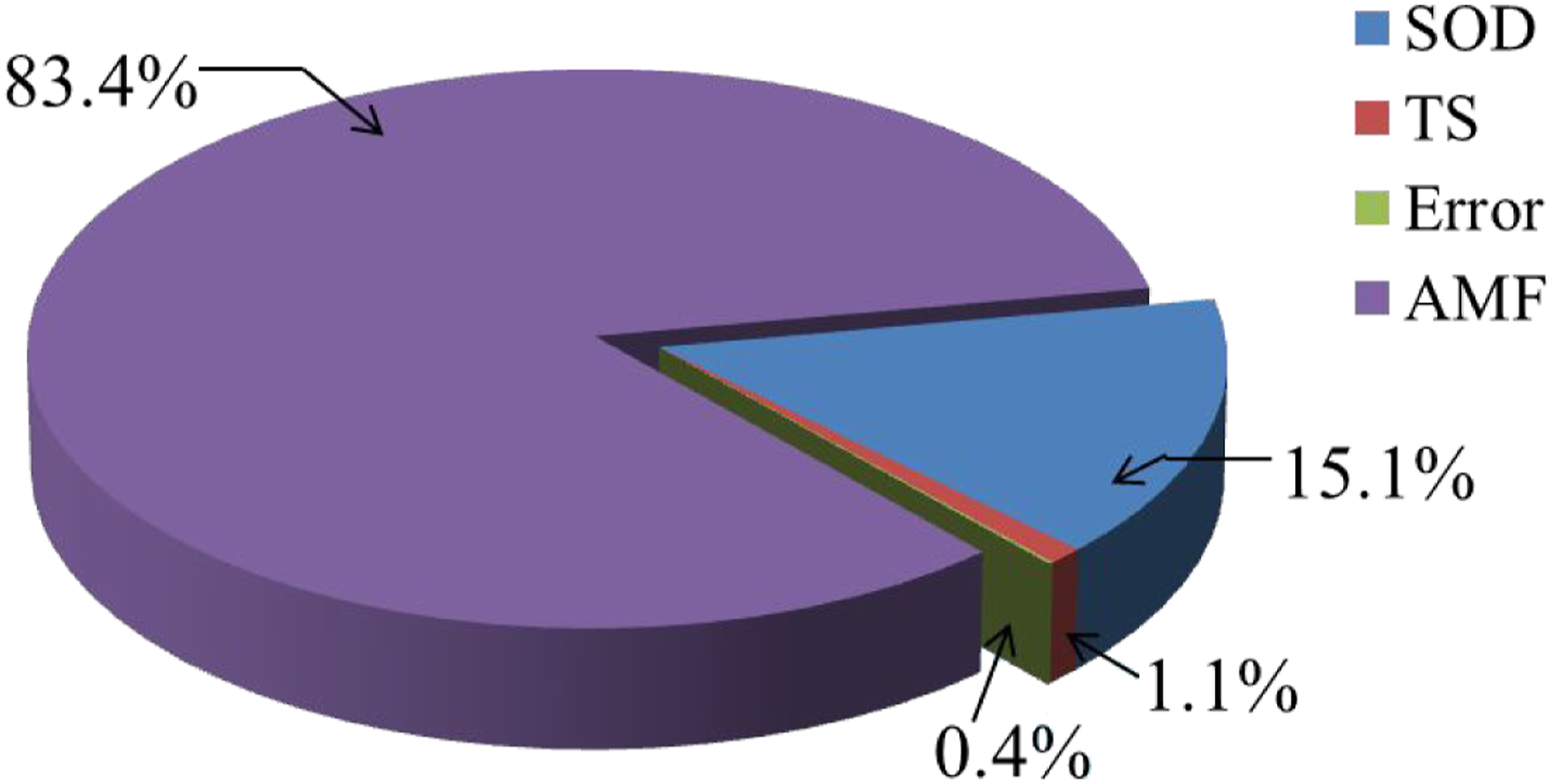
The variation between actual and predicted responses is shown in Figure 9. The Predicted R2 of 0.8127 reasonably agrees with the adjusted R2 of 0.9528. Hence the model prediction was found to be congruent with the experimental values. Figure 10 shows the impact of input process parameters in influencing surface roughness. It was found that abrasive mass flow rate (AMF) was the maximum significant parameter with 83.4% contribution, followed by standoff distance (SOD) with 15.1% contribution. Predicted versus actual results for surface roughness. Contribution of process parameters in surface roughness.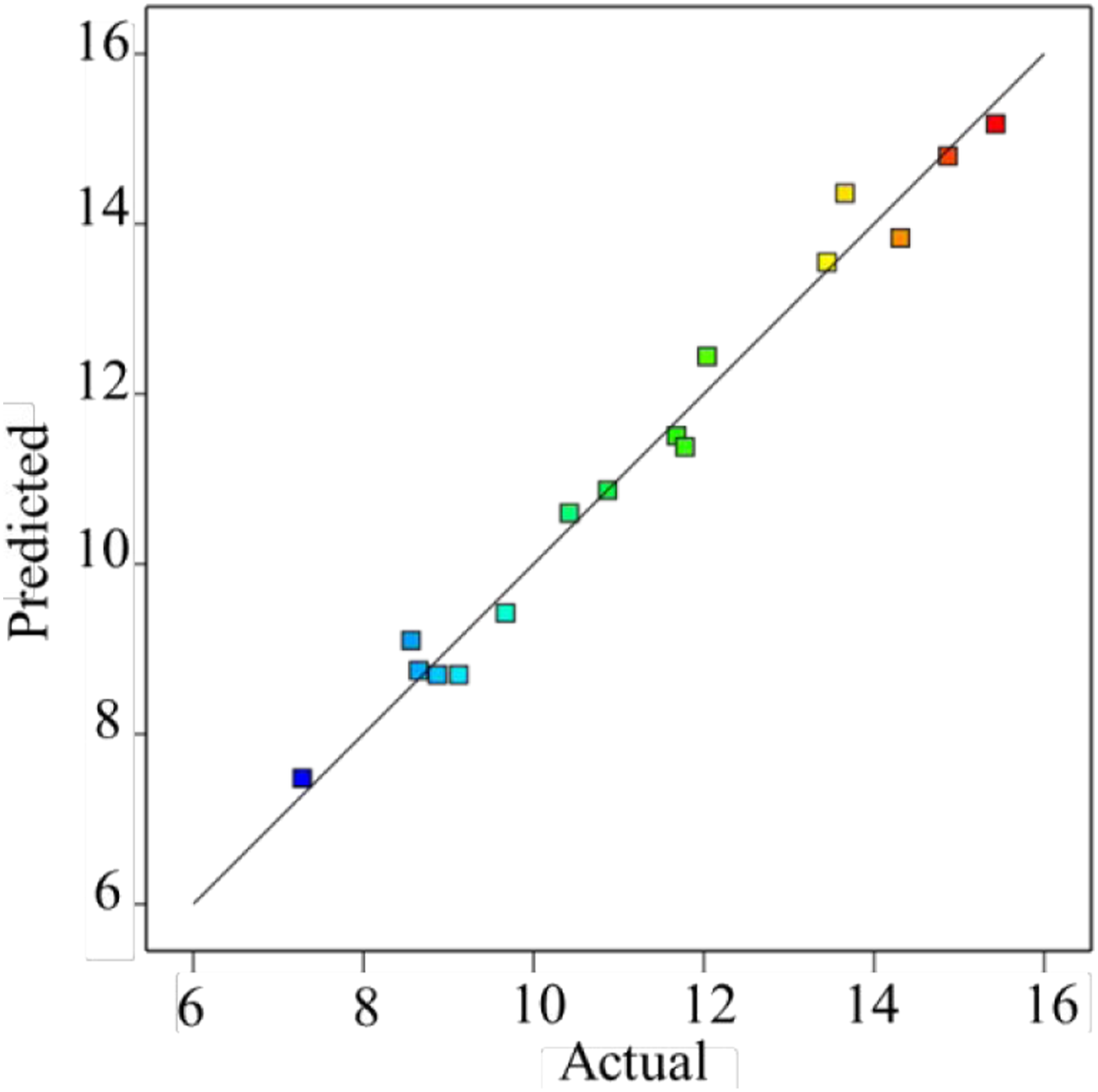
Kerf angle
In general, the top width of the kerf was more comprehensive than the bottom width. At 5 mm and 4000 mm/min, the kerf width was high at the top compared to the composite’s bottom kerf. This phenomenon was due to the abrasives’ increased tangential movement, which creates an uneven morphology at the concave and the convex side of the cut surface.
31
From Figure 11(a), it was observed that the influence of the traverse speed harms the top kerf. The quicker passing of the water jet permits fewer garnet particles to strike the composite material, creating a narrower slot.
32
3D plot obtained from RSM showing effect of process parameter on kerf angle.
Figure 11(b) shows the effect of standoff distance and traverse speed on kerf angle. The kerf angle was found to increase with increasing standoff distance. It could be attributed to reducing the abrasive cutting ability. The findings from the past research28,33 agree with these present observations. The garnet particles strike the top surface of the composite with more energy initially than continuously lose some of the energy during propagation of the jet. At a higher AMF rate, the more significant amount of abrasive particles contributes to the cutting action, producing a wider kerf. Moreover, this trend was similar to the Kenaf E-glass fiber composite examined in an earlier AWJM study. 34 Thus, the main primary parameter about kerf angle was standoff distance.
Therefore, the final equation for kerf angle (KA) in terms of a coded factor was shown in equation (3)
Table 4 ANOVA for kerf angle.

The variation between actual and predicted responses for kerf angle is shown in Figure 12. The Predicted R2 of 0.9919 was reasonable with the adjusted R2 of 0.9983. Hence, the model prediction was congruent with the experimental values. Figure 13 shows the influence of input process parameters on the kerf angle. It was found that SOD was the most significant parameter with 87.2% contribution, followed by AMF with 9% and TS with 3.6% of contributions. Predicted versus actual results for kerf angle. Contribution of process parameters in kerf angle.

Effect of standoff distance on spalling defect
Some common defects that occur while using the AWJM process in composite material are burrs, delamination, spalling, and interlaminar cracks. The defects like crack propagation, dimensional inaccuracy, and spalling should be minimized while machining composite materials. The amount of defects can be minimized by selecting the appropriate process parameter. Significantly, while doing unconventional machining processes (AWJM), the spalling defect was usually observed in the exit plane.
35
Figure 14 shows the microscopic images of spalling defects in the exit plane. The caption in Figure 14 refers to the standoff distance (SOD) between nozzle and composite (1–5 mm). The erosive effect of abrasive mixed high-velocity water jet causes a spalling defect in the composite material. When the SOD increases, the focal point of the diverging water jet varies and increases the top kerf. Interning the diffused jet region at the end of the exit kerf incapacitates the epoxy bonding and leads to spalling defects.36–38 Spalling defects at the exit plane for different process parameters.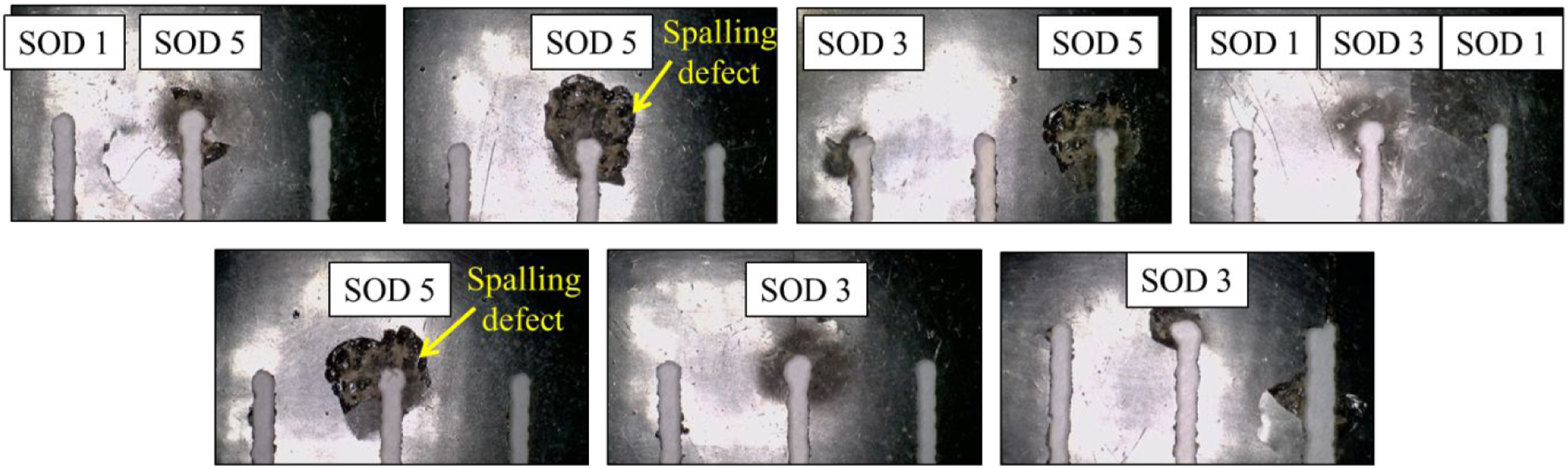
Surface morphology
The lateral machined surfaces of the same samples expose three different zones, which were identified through microstructural analysis: (1) Initial pitting region (IPR), which was caused due to the impingement of garnet particles; (2) Smooth ploughing region (SPR), it was the cutting zone in the brittle region; (3) Rough cutting region (RCR), which was the zone in the ductile region. 31
The hybrid composite by AWJ machining by scanning electron microscope (SEM) is shown in Figure 15. The different surface morphology in the machined surface was produced due to the sudden penetration of garnet particles. The SEM images of the machined surface texture show that the material removal was carried out in micro ploughing and micro pitting, as shown in Figure 15(a) and (b). In a previous research study, the cutting mechanism in IPR, SPR, and RCR was claimed to be deformation wear, cutting wear, and erosive wear, respectively.39,40 In the IPR region, garnet particles have adequate kinematic energy to create ploughing on the brittle surface. This small damaged area was considered a fillet or rounded corner at the jet affected zone caused by garnet bombardment. As the garnet particles penetrate the hybrid composite, some kinetic energy was utilized to erode the material through micro-cutting (crack initiation and propagation), as shown in Figure 15(c). In ductile wire mesh, the material was mainly removed by low angle impact of garnet particles, leading to micro pitting.
41
Figure 15(d) typically shows the effect of micro pitting in the form of peaks and valleys, which causes the surface roughness to increase. The interfacial debonding or delamination occurs between wire mesh and epoxy; due to the increase in mass flow rate of garnet particles. The surface roughness Ra for the machined surface can be calculated using a surface profilometer (MFW 250) through the specific 2D line diagram profiles, as shown in Figure 16. The arithmetic means value (Ra) was different in wire mesh and epoxy regions obtained from the line profiles. SEM images of machined surfaces (a) lateral machined surfaces with standoff distance 5 mm (b) Material removal mechanism (c) plastic deformation of wire mesh (d) peaks and valley in ductile material. 2D line diagram of mean surface roughness measurement.

Conclusion
The outcome of the current experimental study is mentioned below: • The abrasive mass flow rate and standoff distance were the most significant factor affecting the surface roughness values by 83.4% and 15.1%. • Minimum standoff distance (1mm) and medium abrasive mass flow rate (750 g/min) produce reduced surface roughness of 7.28 μm. • The standoff distance (87.2%) followed by the abrasive mass flow rate (9%) has a physical and statistical effect on the kerf angle. • The presence of micro ploughing, crack propagation and wear tracks were observed in the brittle region (epoxy) through morphological study. Comparatively, micro pitting and peak formation were witnessed in ductile material (wire mesh) through high magnified SEM images.
The outcome of the present research study was beneficial for producing good machining quality parts of natural fiber hybrid composite by abrasive water jet machining process.
Footnotes
Declaration of conflicting interests
The author(s) declared no potential conflicts of interest with respect to the research, authorship, and/or publication of this article.
Funding
The author(s) received no financial support for the research, authorship, and/or publication of this article.
Ethics approval
The manuscript should not be submitted to more than one journal for simultaneous consideration.
Consent to participate
• Consent was obtained from all individual participants included in the study.
• Informed consent was obtained from legal guardians.
• Written informed consent was obtained from the parents.
• Verbal informed consent was obtained prior to the interview.
• The patient has consented to the submission of the case report for submission to the journal.