
Abstract
Metal matrix composites are difficult to machine in traditional machining methods. Abrasive water jet machining is a state-of-the art technology which enables machining of practically all engineering materials. This article deals with the investigation on optimization of process parameters of abrasive water jet machining of hybrid aluminium 7075 metal matrix composites with 5%, 10% and 15% of TiC and B4C (equal amount of each) reinforcement. The kerf characteristics such as kerf top width, kerf angle and surface roughness were studied against the abrasive water jet machining process parameters, namely, water jet pressure, jet traverse speed and standoff distance. Contribution of these parameters on responses was determined by analysis of variance. Regression models were obtained for kerf characteristics. Contribution of traverse speed was found to be more than other parameters in affecting top kerf width. Water jet pressure influenced more in affecting kerf angle and surface finish. The microstructures of machined surfaces were also analysed by scanning electron microscopy. The scanning electron microscopy investigations exposed the plastic deformation cutting of hybrid 7075 aluminium metal matrix composite. X-ray diffraction analysis results proved the non-entrapment of abrasive particle on the machined surface.
Introduction
Metal matrix composites (MMCs) are utilized widely in aircraft, automotive, electronic packing and so on, because of their better electrical and thermal conductivity, high strength and specific stiffness properties. The excellent mechanical properties at low cost make them a lucrative option for replacement of conventional metals.1,2 The typical reinforcing materials used in developing aluminium MMC are B4C, SiC, TiC, Al2O3, ZrO2 and WC. Hybrid composites comprise a minimum of three constituents having atomic level bonding between them in the composite, each of which develops from a separate ingredient material which is already present in the composite. 3 Although the MMCs afford better weight to strength solutions to the industrial needs, difficulty in machining these materials prevents more replacement of MMCs with conventional materials. Because of the presence of the highly abrasive ceramic reinforcements, machining of MMCs poses difficulty when traditional machining was used. 4 For machining of MMCs, the nontraditional machining techniques such as laser, electrical discharge machining (EDM) and ultrasonic machining are widely used. The major problems with these machining methods are recast layer, dross attachment and thermal weakening. This problem is overcome by abrasive water jet machining (AWJM). 5 AWJM is a nontraditional manufacturing method for machining materials by means of a high-velocity slurry jet, formed as a result of injecting abrasive particles to a water jet ejected by an orifice. It involves abrasion cutting and wear cutting mechanism to remove material from the target surface. 6 Hashish 7 formed a set of mathematical model to relate the process parameters to the process output variables in water jet technique. Vikram and Ramesh Babu 8 proposed a new approach for modelling the three-dimensional (3D) topography produced on abrasive water jet (AWJ) cut surface. Cao et al. 9 built computational fluid dynamics–based analysis for the determination of the material removal rate in fluid jet polishing. Karakurt et al.10–12 studied the effects of the AWJ operating variables on the cutting rocks and granites and found the optimum parameters of AWJM. Aydin et al. 13 performed an experimental study on the cut depth in the AWJ cutting of rock. The results showed that the cut depths decreased with increasing traverse speed and decreasing abrasive size. On the other hand, increase in the abrasive mass flow rate and water pressure resulted in increase in the cut depths. Aydin et al. 14 modelled the rock cutting performance of AWJ. Kerf angle (KA) was considered as a performance criteria and modelled using artificial neural network (ANN) and regression analysis based on the operating variables. Siores et al. 15 investigated the AWJ cutting of ceramics considering the cutting depth prediction models and experimental results to optimize the process efficiency. Hocheng and Chang 16 discussed the formation of kerf in ceramic plate by an AWJ. The wall finish achieved was because of the mesh size of the abrasives: sufficient hydraulic pressure with fine abrasives will yield a smooth surface comparable to that from grinding. Hlaváč et al. 17 used the declination angle for the prediction and control of the AWJ cutting quality. Ramulu and Arola 18 predicted the depth of cut due to cutting and deformation wear for graphite/epoxy composite materials employing regression analysis. Wang 19 investigated the cutting performance and erosive process while machining polymer matrix composites by AWJM and proposed a predictive model. Shanmugam and Masood 20 investigated the KA while machining by AWJM of epoxy pre-impregnated graphite woven fabric and glass epoxy composites with the dimensional technique and adopted the energy conservation approach for relating the kerf taper angle to the operating parameters in a form of a predictive model. Shanmugam et al. 21 explored the mechanism of delamination in graphite/epoxy composites under AWJ machining. It was found that crack tips were generated by the shock wave impact of the water jet at the initial cutting stage, while delamination was a result of water penetration into the crack tips that promoted water-wedging and abrasive embedment. Kalirasu et al. 22 studied about the responses of the AWJM parameters with two different reinforcement sources, namely, bi-directional glass mat (synthetic) and coconut sheath (natural) fibre, in a polymer matrix composite. They found the higher crack resistance in the glass mat composites and reasoned it to the better interfacial adhesion capability. Kong and Axinte 23 investigated machining of TiAl using AWJM for generic design of an aero engine component. The response of a TiAl alloy to AWJ cutting process variables was determined to enable generation of high-integrity surfaces. It was established that the AWJ process has a very high capability (e.g. satisfactory geometrical accuracy, surface quality, minimum surface anomies) to cut TiAl alloy despite grit embedment. Hascalik et al. 24 studied the effect of traverse speed on AWJM of Ti–6Al–4V alloy. The study concluded that the traverse speed of the jet was a significant parameter on the surface characteristics, and the widths and features of different regions formed in the cutting surface varied according to the traverse speed. Arola and Hall 25 adopted AWJ for the surface treatment of commercially pure titanium (cpTi), and the contribution of treatment parameters to material removal and the deposition of particles within the substrate were studied. The minimum and maximum concentration of particles entrapped in the AWJ treated cpTi (in percent surface area covered) was 2.5% and 21.6%, respectively. Müller and Monaghan 26 predicted the various mechanism of metal removal by three non-conventional machining methods by machining aluminium composites through EDM, laser and AWJM. Ramulu et al. 27 studied the hydro-abrasive erosion characteristics for 30 vol.% SiCp/6061-T6 Al composite material and 6061-T6 aluminium alloy at steady-state conditions using AWJs. The experiments also proved that the erosive wear rates for the 30 vol.% SiCp/6061-T6 Al composite decreased 2-fold than the erosive wear rates of the 6061-T6 aluminium alloy. Hloch et al. 28 conducted experiments using design of experiment method to study the significance of AWJM process parameters such as jet traverse speed, abrasive mass flow rate and pressure in machining cast aluminium. Cenac et al. 29 studied AWJ milling of aluminium 2024 T3 considering the machined depth as an experimental factor and the feed rate as a product. Deris et al. 30 formed hybridization model of support vector machine (SVM) and grey relational analysis (GRA) for predicting surface roughness value of AWJM of aluminium 7075. Cayadas and Hasçalık 31 developed ANN and regression model to predict surface roughness in AWJM process of AA7075 aluminium. It was statistically determined that the water pressure and the abrasive flow rate have a most significance in influencing the surface roughness of granites. Chakravarthy and Ramesh Babu 32 presented a new approach, based on the principles of fuzzy logic and genetic algorithm (GA) for selecting optimal process parameters in AWJ cutting of granite to any predetermined depth, using multi-criteria optimization technique. Ceramic particle–reinforced aluminium MMCs established better mechanical properties such as elastic modulus, hardness and tensile strength than bare aluminium alloys 33 and find their application in automobile and aeronautical parts because of their high ratio of strength, stroke density and improved wear resistance. Less density, high elastic modulus, high refractoriness and high hardness of B4C was made to select it as one of the reinforcement for preparing MMCs. TiC is a relatively new reinforcement in MMCs and possess good properties such as wettability, thermal stability and distribution in aluminium metal matrix. 34 From the literature survey, it can be seen that there are very little papers on the AWJM parameter optimization while machining aluminium 7075 composite. Furthermore, there is no paper available for AWJM parameter study on hybrid aluminium 7075 MMCs’ machining. This article focuses on the machinability of hybrid aluminium 7075 MMCs by an AWJM method. The results of the machining of these hybrid composites will be discussed in terms of the kerf characteristics as a function of the water jet pressure, jet traverse speed and standoff distance. Based on the results of the experiments conducted, some concluding remarks are given as to prove the feasibility of these machining methods for machining hybrid aluminium 7075 composites and the effect of various parameters on the desired response characteristics. Scanning electron microscope (SEM) images are taken to study the fracture behaviour of MMCs by AWJ machining.
Materials and methods
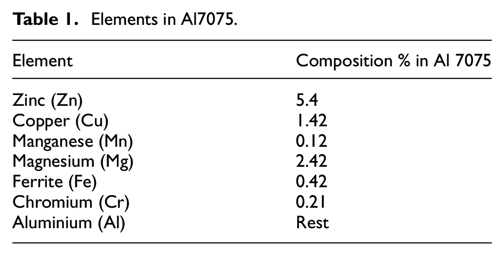
Aluminium 7075 hybrid MMCs with 5, 10 and 15 vol.% of titanium carbide (TiC) and boron carbide (B4C) were used in this study. The particle sizes of reinforcement TiC and B4C are 5–15 and 10–25 µm, respectively. The hybrid aluminium composites reinforced with TiC and B4C were produced by two-step stir casting method. The Al 7075 billets were placed into the furnace and melting was carried out until a uniform temperature of 740 °C was reached. The melt was then permitted to cool to 590 °C to a semi-solid state. The slurry was stirred mechanically by mild steel stirrer. During stirring, a vertex was formed and the equal amount of preheated TiC and boron carbide mixture was added into the melt. After the first step stirring, the composite slurry was again heated and kept at a temperature of 740 °C ± 10 °C and then stirred mechanically for 10 min at an average stirring rate of 350 r/min. Casting was then accomplished on the prepared mild steel die at a pouring temperature of 710 °C. Cast composites were cut with dimensions of 70 mm × 50 mm × 10 mm. Table 1 shows the chemical composition of aluminium 7075 alloy. Figure 1(a) and (b) shows the microstructure of as-cast composite samples of aluminium 7075 composite with 5% and 15% TiC and B4C particles, respectively. A close observation of the micrographs reveals the uniform distribution of TiC and B4C particles in the aluminium matrix. Figure 1 shows slight agglomeration of TiC and B4C particles in the 15% reinforcement MMC compared to 5% MMC.
Elements in Al7075.
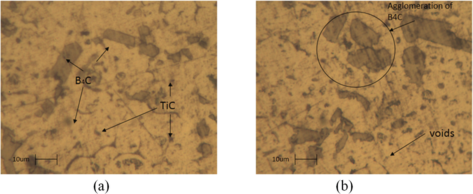
Microstructure of (a) Al7075 (2.5% TiC + 2.5% B4C) and (b) Al7075 (7.5% TiC + 7.5% B4C).
Experimental study details
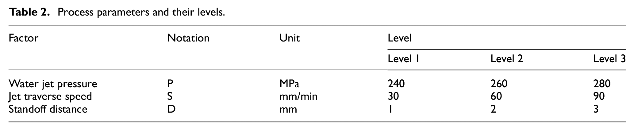
The experiment was carried out on a Dardi water jet cutter, equipped with intensifier high-output pump (380 MPa), traverse speed of 0–15 m/min and a cutting accuracy of ±0.1 mm, to cut 25-mm-long slots on test specimens of 10-mm thick. Figure 2(a) shows the AWJM machine used in this investigation. The shape of the abrasive particle plays a vital role in machining. 6 Figure 2(b) shows the kerf geometry of the cut workpiece. The abrasives used for cutting were garnet with 80 mesh size. The jet was passed perpendicular to the workpiece surface. The orifice assembly contains a carbide nozzle insert 0.723 mm in diameter. The abrasive mass flow rate was maintained at 5 g/s throughout the experiment. The most principle process parameters such as water jet pressure, traverse speed and standoff distance were selected based on the earlier works in machining of pure aluminium. 28 Table 2 shows the range of important process parameters and their levels. The kerf width was measured using optical microscope. The average surface roughness (Ra) of AWJ-machined samples was measured using Talysurf surface roughness measurement device. The measurements were taken at a distance of 5 mm from the top of the cut surface. The machined surfaces were investigated using A LEO 32 SEM. Table 3 gives the information about the parameters used for conducting the experiments. Each test was carried out trice and the average of the results was taken for further study.
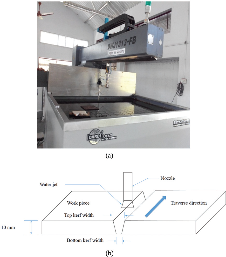
(a) Experimental set-up for AWJ cutting of rectangular MMCs and (b) kerf geometry.
Process parameters and their levels.
Experimental design.

Results and discussion
Effects of jet traverse speed
AWJ removes the aluminium matrix by eroding action but it pulls, disrupts or jumps over the reinforcement particles. Figure 3(a)–(c) evaluates the effect of jet traverse speed on kerf characteristics since cutting efficiency of jet decreases due to particle fragmentation, and the kerf width diminishes from top to bottom of cut. As the jet traverse speed was increased, the kerf top width decreased. When the addition of reinforcement particle increased, the top kerf width started decreasing. This is because of the increase in hardness of the work material. It is seen from Figure 3(b) that the KA is found to increase with increasing traverse speed from 30 to 90 mm/min. This is because of the reduction in kerf bottom width generated by the jet as the traverse speed increases. Cutting at a low traverse speed is, therefore, preferred for small KAs. Surface roughness increased with traverse speed; higher speeds hinder the complete machining of kerf wall. This can be reasoned to the fact that when the traverse speed increases, less numbers of abrasive particles take part in cutting. Figure 3(c) depicts the increase in surface finish with traverse speed. When adding more reinforcement particles, the surface roughness worsens. The reason for the increase in the surface roughness is that the reinforcement particles are pulled out of the matrix creating minor cavities on the surface of the composite. 26 Hence, the presence of more number of particles poses for the problem of more minor cavities leading to poor surface finish.
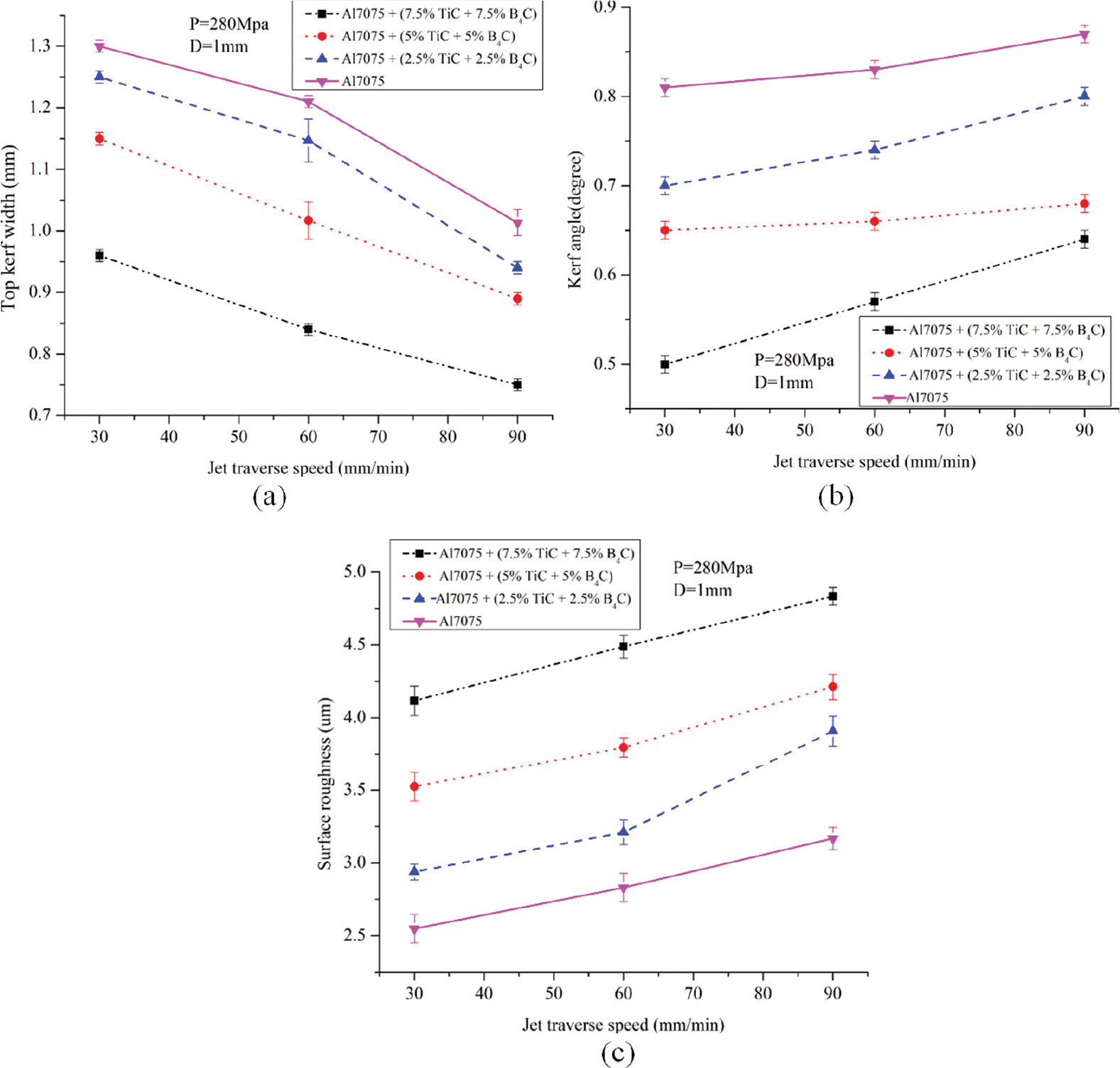
Effects of jet traverse speed on (a) top kerf width, (b) kerf angle and (c) surface roughness.
Effect of water jet pressure
It can be seen from Figure 4(a) that the top kerf width appears to increase with the increase in water jet pressure. The greater water pressure produces greater kinetic energy of jet impinging onto the workpiece material and create a wide top kerf. The increase in reinforcement reduces the jet capability to open a wider kerf. The effect of water jet pressure on KA is shown in Figure 4(b).
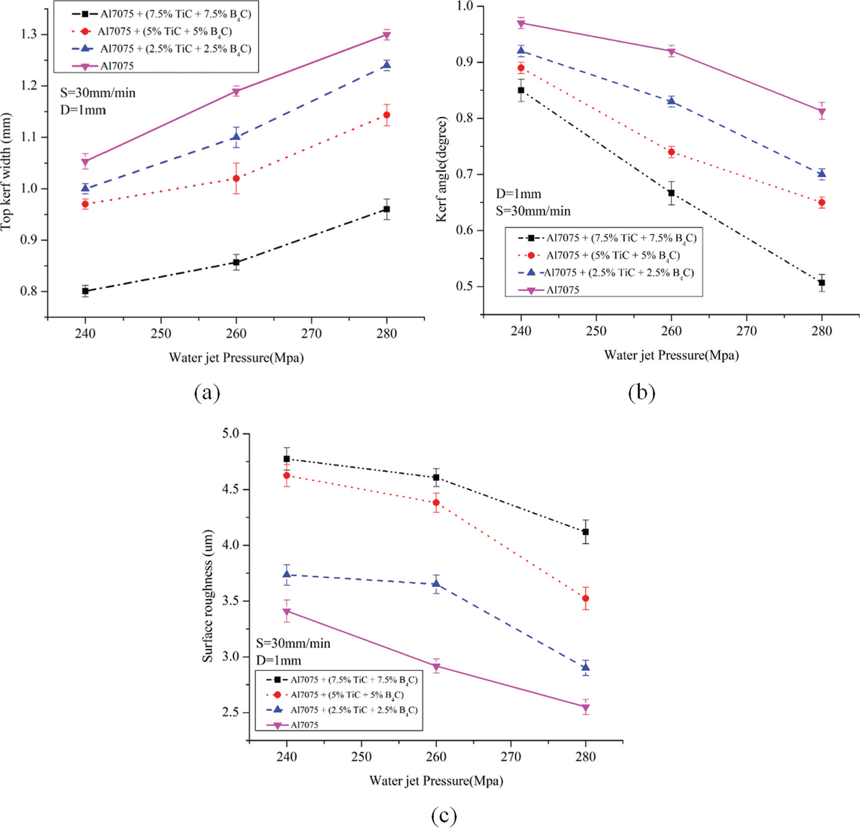
Effect of water jet pressure on (a) top kerf width, (b) kerf angle and (c) surface roughness.
The KA decreases with the increase in the water pressure because at higher water pressure, the jet kinetic energy increases high momentum transfer of the abrasive particles, creating a low kerf bottom. Therefore, the difference in top and bottom kerf width is reduced, resulting in minimum kerf taper angle. The kinetic energy of the abrasive particles increases at higher hydraulic pressure and enhances their capability for cutting. 35 As a result, the surface roughness decreases as depicted in Figure 4(c). As the reinforcement percentage increases, the surface roughness worsens. Whenever the supply pressure offers sufficiently high energy to the abrasives, the cutting process is allowed to be carried out without severe jet flaration which in turn minimizes the waviness pattern on the surface.
Effect of standoff distance
Figure 5(a) shows that the top kerf width increases with an increase in the standoff distance.
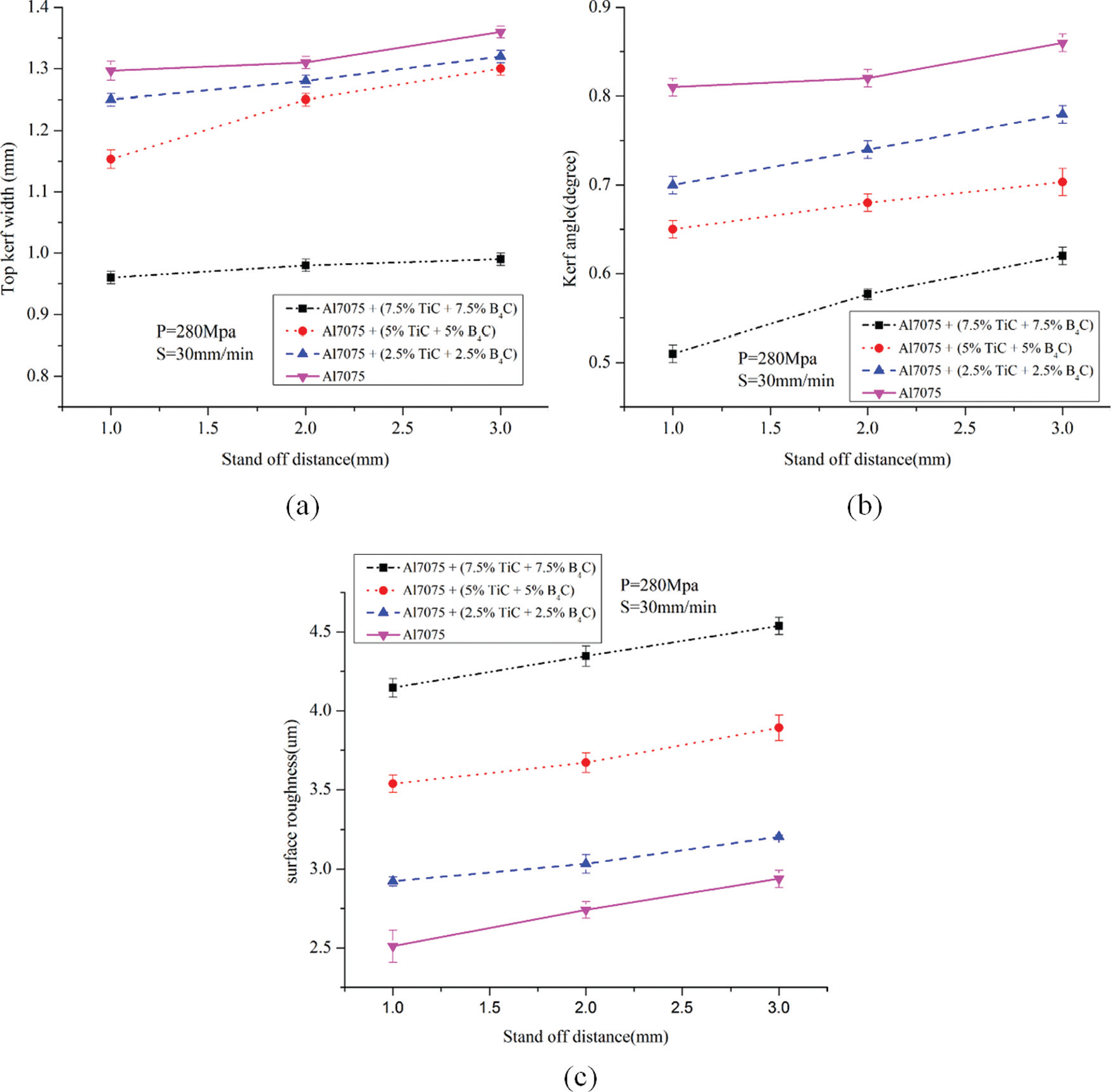
Effect of water jet pressure on (a) top kerf width, (b) kerf angle and (c) surface roughness.
This may be justified by the fact that the jet divergence occurs when high-velocity water jets spread out as they leave from the focus tube. The KA increases with the increase in standoff distance as shown in Figure 5(b). Figure 5(c) shows the variation in surface finish with respect to water jet pressure. As the standoff distance increases, the material surface is open to the downstream of the jet. The jet starts to diverge at downstream and loses its coherence thereby dropping the effective cutting area that directly reflects in the kerf taper angle. A lower standoff distance which may produce a smoother surface due to increased kinetic energy may be selected. The higher the standoff distance, the more the external drag from the surrounding environment. 36 Higher standoff distance makes the jet to enlarge before hitting the target materials which makes the water jet vulnerable to external drag from the surrounding atmosphere. Therefore, an increase in the standoff distance results in an increased jet diameter and reduces the kinetic energy of the jet at the time of contacting the target materials. So surface roughness rises with the increase in standoff distance.
The machined surface characteristics
The AWJM-machined Al7075 MMC surfaces were studied with help of SEM after cleaning to examine the machined surface characteristics. A small damaged region was made by the initial jet impact where an indentation was created on the edges of the top kerf by the water jet. Below this, the cutting marks can be seen. This may have been due to the two erosion stages (cutting wear and deformation wear) as proposed by other workers 37 for ductile material cutting.
The machined surface contains three regions, namely, initial cut region (ICR), smooth cut region (SCR) and rough cut region (RCR). 38 Abrasive particles have sufficient kinetic energy during entry period to erode the material. Figure 6(a)–(d) shows the SEM image of the machined surface. The ploughing mark in Figure 6(a) clearly shows the abrasion mechanism of material removal in AWJM. Since the thickness of the specimens was minimum, the deflection of the jet was not observed here. The SCR was only obtained. Figure 6(b) further shows the plastic deformation of the material due to high traverse speed. From Figure 6(b), this can also be viewed that with the increase in the reinforcement particles, the matrix materials not only ploughed by the abrasive jet but also the reinforcement particle by pelting of abrasives hitting with high kinetic energy as shown in Figure 6(c). When observing the morphology of the cutting front, the cutting action as a result of the impingement of individual abrasive particles was evident, as shown in Figure 6(d) as evidenced by Wang and Wong. 39 Figure 6(e) shows the X-ray diffraction (XRD) image of the cut surface. The machined surfaces were examined for entrapment of garnet abrasive particles. The XRD image at the machined surface showed that there are no garnet particles. This is because of the high momentum of the garnet particles and also the thickness of the work specimen is minimum.
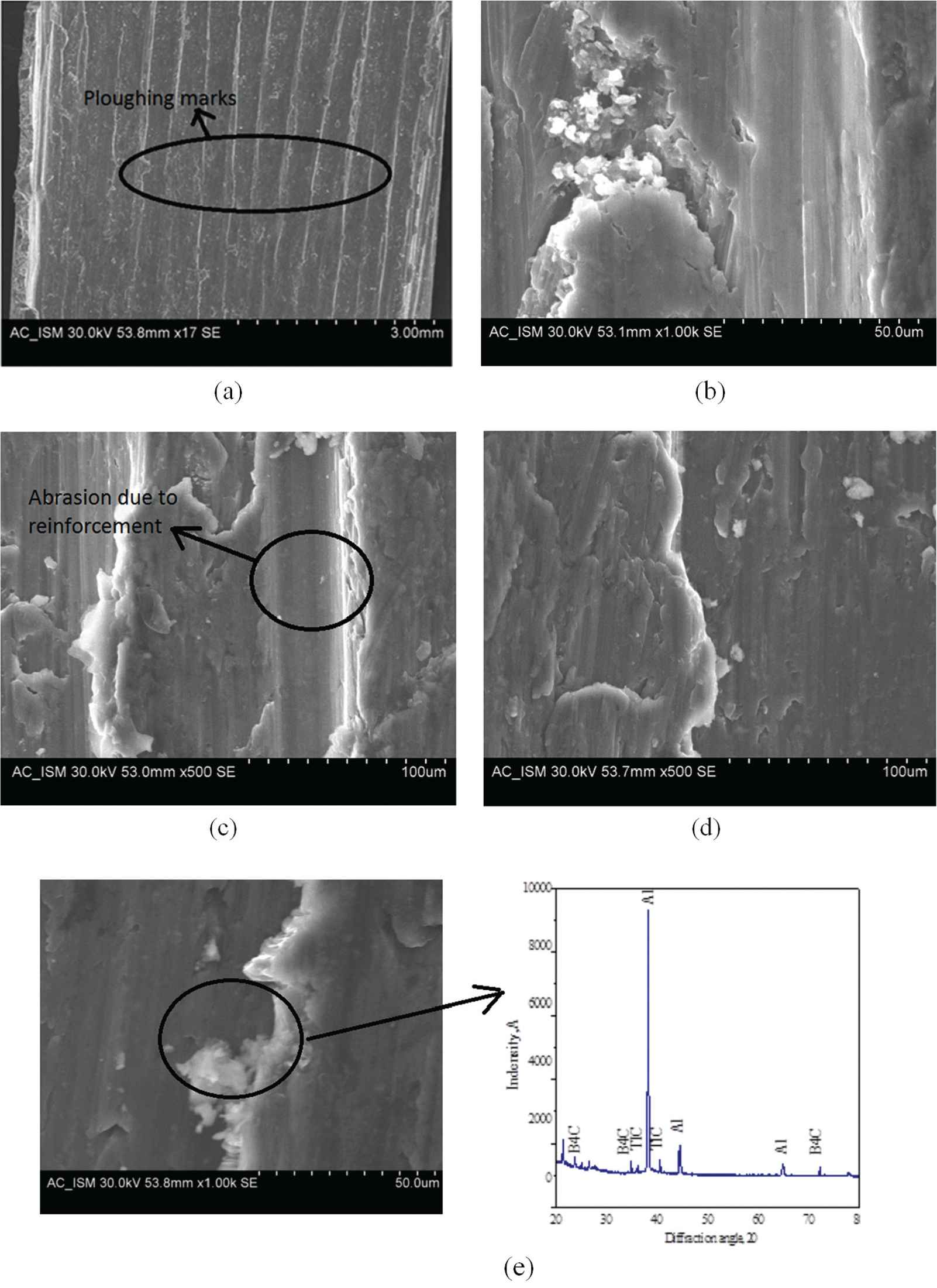
SEM image of the machined surface (water jet pressure = 280 MPa, jet traverse speed = 30 mm/min, standoff distance = 1 mm) (a) ploughing mark; (b) plastic deformation; (c) abrasion; (d)morphology of cut.
Analysis of variance for top kerf width
The effect of control factors were examined through the analysis of variance (ANOVA). It is a computational technique performed mainly to learn about the influence of various design factors and to notice the degree of sensitivity of the result to different factors disturbing the quality characteristics. F-ratio value is a statistical equivalent to Taguchi’s signal-to-noise ratio for the control factor effect versus the experimental error. It utilizes the information based on sample variances to state the relationship between the power of the control factor effects and the power of the experimental error. Larger F-ratio value shows that there is a greater modification on the performance characteristic due to the deviation of the process parameter. Table 4 shows the ANOVA for the response top kerf width using a general linear model. Table 4 displays F-ratios, p values and the percentage contribution (%C) of each source to the total variation representing the degree of influence on the depth of jet penetration. This analysis was performed for a significance level of 0.05, that is, for a confidence level of 95%. The F-ratios given in Table 4 for water jet pressure, traverse rate and standoff distance are more than F-ratios available in the statistical tables. Furthermore, the p values calculated from the ANOVA analysis for these parameters are less than 0.05. Therefore, it can be concluded that these parameters are most statistically significant parameters influencing the top kerf width. Among the three input parameters, the contribution of traverse speed is more in affecting the top kerf width. For higher reinforcement MMCs, the contributions of traverse speed, water jet pressure and standoff distance are 46.18%, 40.3% and 5.1%, respectively.
Results of analysis of variance for top kerf width.
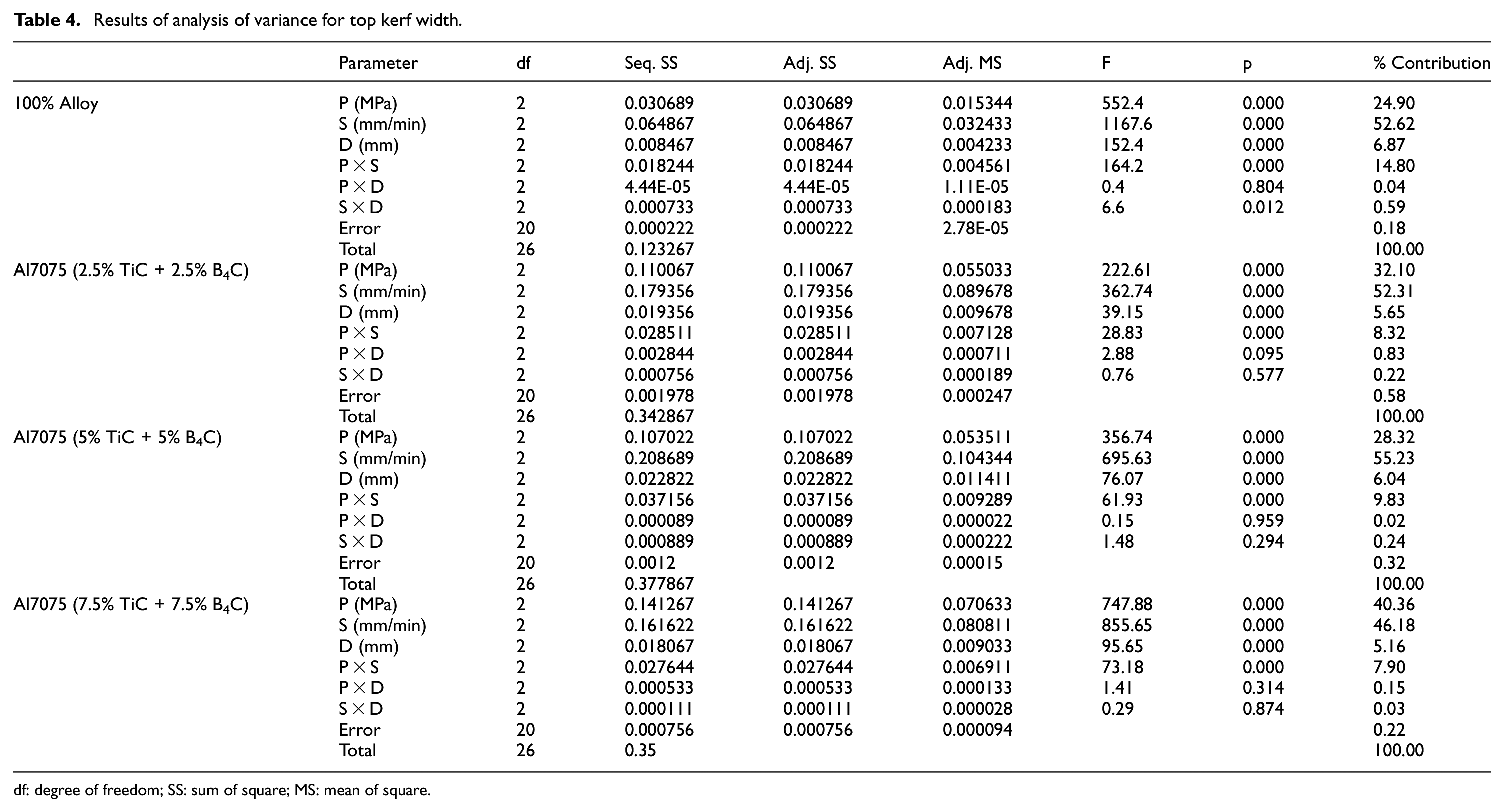
df: degree of freedom; SS: sum of square; MS: mean of square.
ANOVA for KA
Table 5 shows ANOVA parameters for KA. Among the three input parameters, the contribution of water jet pressure is more in affecting the KA. For higher reinforcement MMCs, the contributions of water jet pressure, traverse speed and standoff distance are 60.1%, 20.4% and 10.8%, respectively.
Results of analysis of variance for kerf angle.
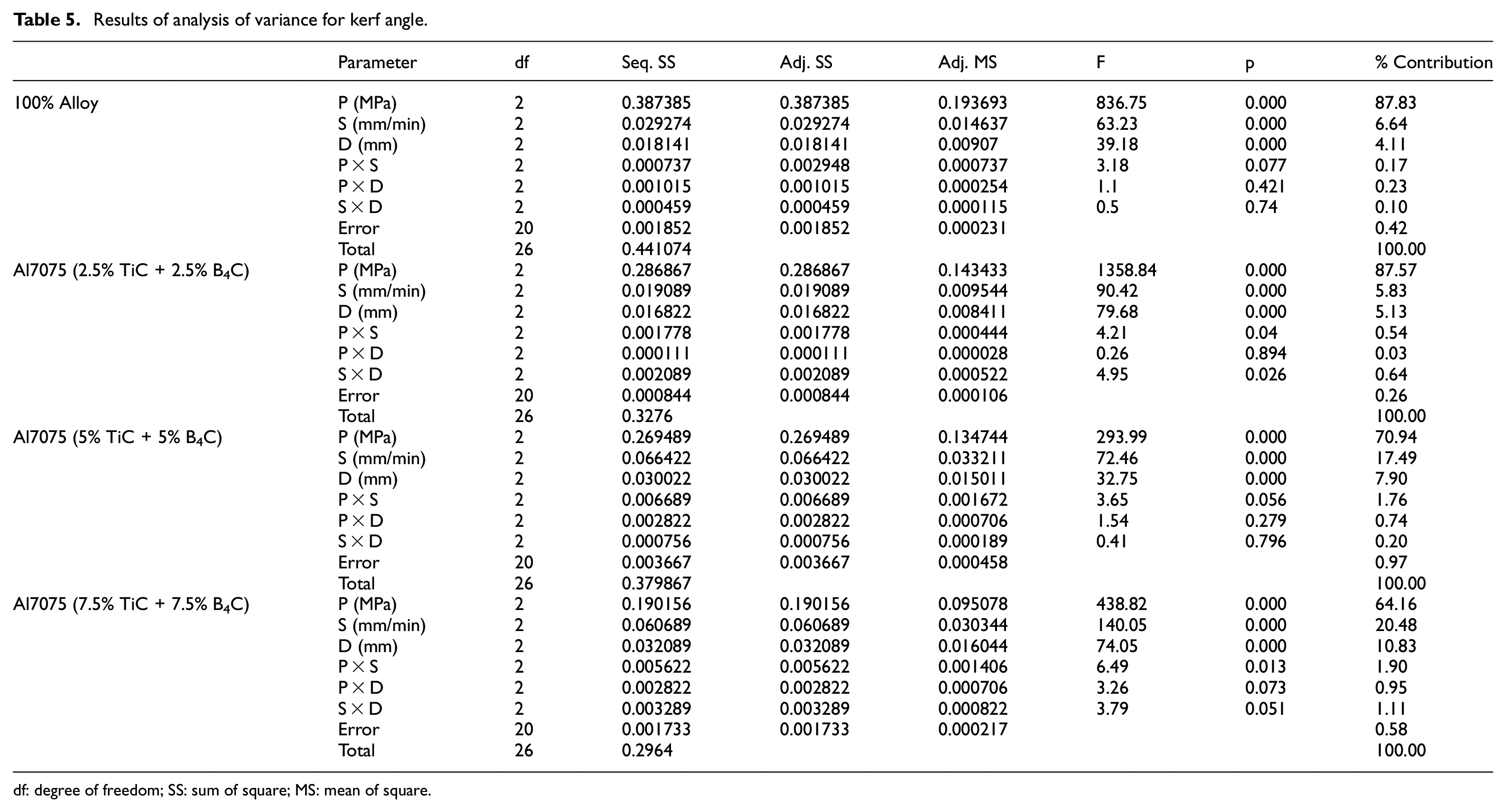
df: degree of freedom; SS: sum of square; MS: mean of square.
ANOVA for surface finish
Table 6 shows the parameters of ANOVA for surface finish. The F-ratios given in Table 6 for water jet pressure, traverse rate and standoff distance are greater than F-ratios from the statistical tables. The p values attained from the ANOVA for these parameters are less than 0.05. Therefore, it can be decided that these parameters significantly influence the surface roughness. The surface finish is mainly influenced by water jet pressure. The contributions of water jet pressure, jet traverse speed and standoff distance in surface finish of 100% alloy are 33.7%, 36.8% and 14.4%, respectively, whereas for MMC with 15% TiC + B4C the contributions of water jet pressure, jet traverse speed and standoff distance in surface finish are 50.08%, 36.6% and 10.6%, respectively, as far as abrasive jet machining is concerned the hardness of the work material is not a problem for machining.
Results of analysis of variance for surface finish.
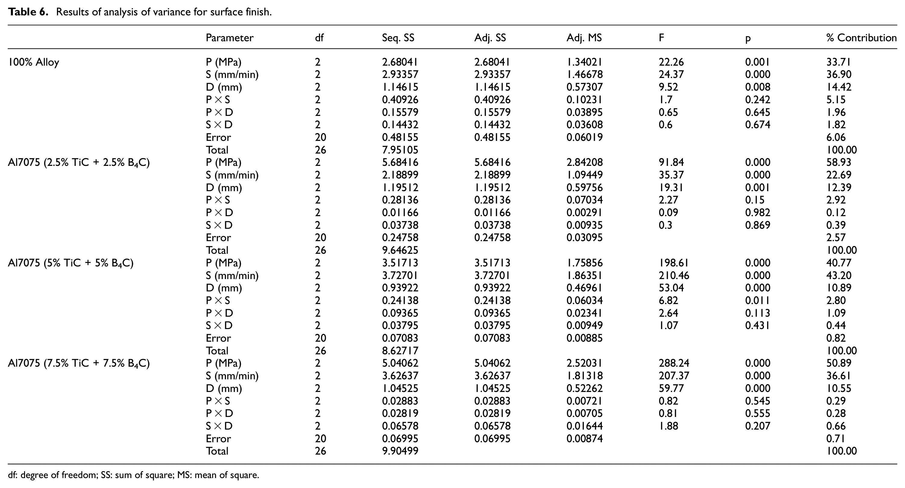
df: degree of freedom; SS: sum of square; MS: mean of square.
Regression analysis
The following regression equations for the top kerf width, KA and surface roughness were obtained from regression analysis using MINITAB software. Table 7 shows the various regression coefficient for predicting top kerf width, KA and surface roughness of different MMCs machined with AWJM. The mathematical model is useful in predicting the machining response of AWJM process during machining of hybrid MMCs. Equations (1)–(3) give the mathematical relationship of various input parameters on the output parameters. The machining parameters can be selected for practical works in manufacturing industries from the model developed here. R2 values for the regression analysis are also given along side
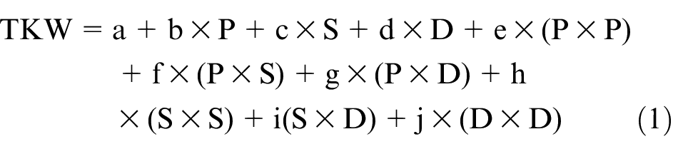
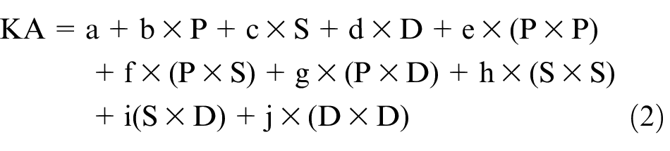
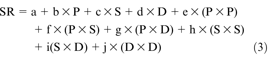
where P, S and D are the water jet pressure, traverse rate and standoff distance, respectively.
Regression coefficients for top kerf width, kerf angle and surface roughness.
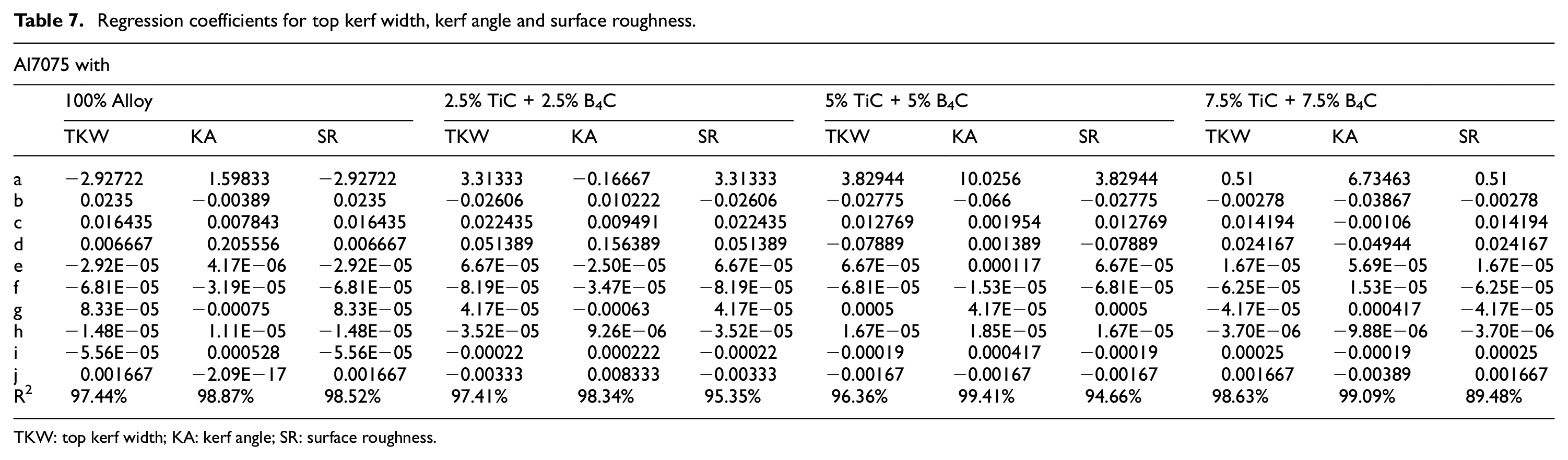
TKW: top kerf width; KA: kerf angle; SR: surface roughness.
After analysing the contribution of all individual and interaction parameters, the non-significant parameters were removed from regression equation. Table 8 gives the values for coefficients in regression equation.
Modified regression coefficients for top kerf width, kerf angle and surface roughness.
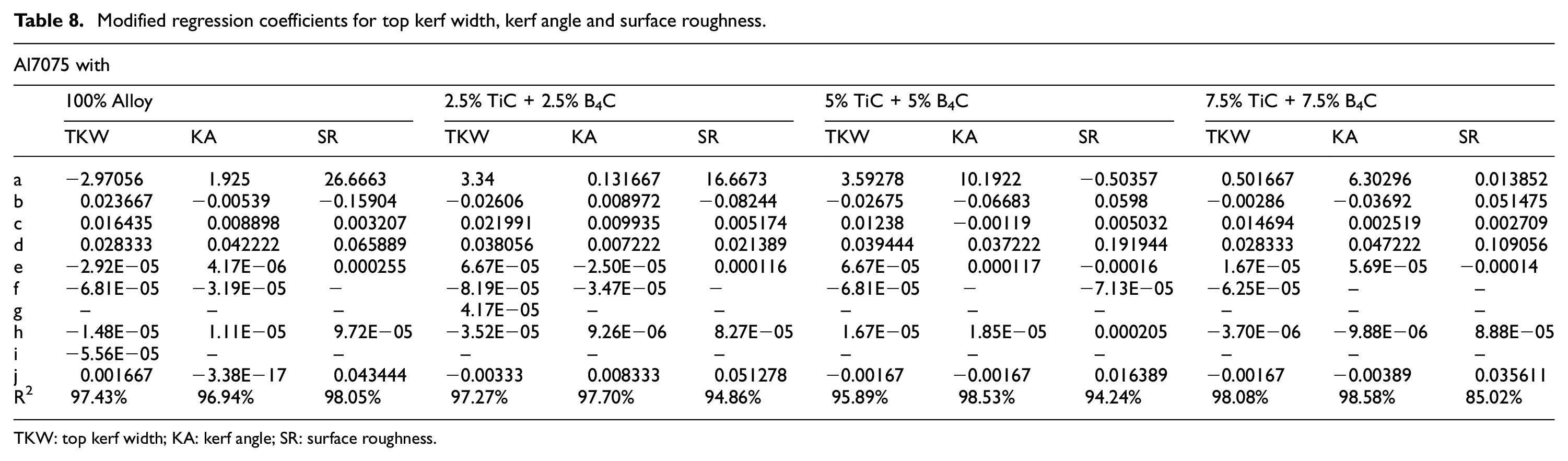
TKW: top kerf width; KA: kerf angle; SR: surface roughness.
Confirmation tests
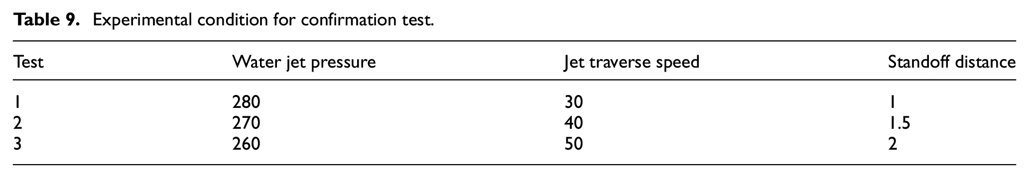
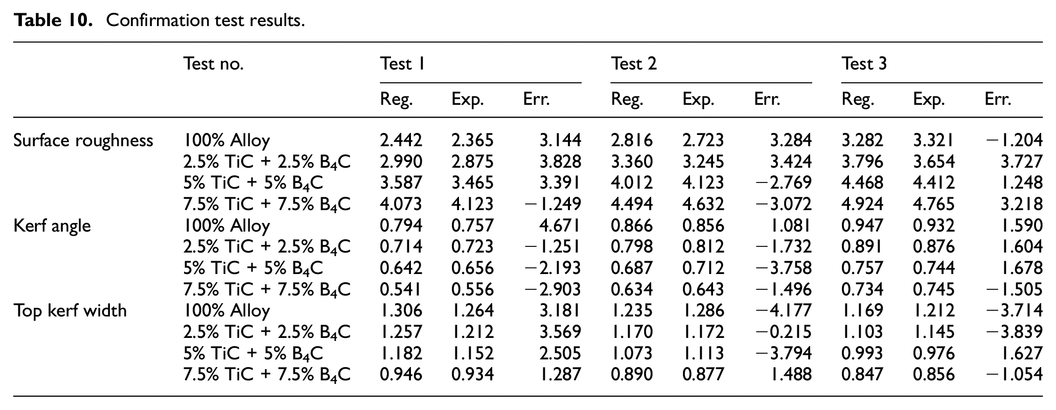
In order to verify the results based on experimental design, the experimental confirmation test was carried out. Table 9 presents the experimental condition for confirmation test. Table 10 indicates the confirmation experimental test results for kerf characteristics. From the confirmation test results, it is observed that the error was less than 5% between the experimentally obtained values and the predicted values by regression model.
Experimental condition for confirmation test.
Confirmation test results.
Conclusion
A study of AWJ cutting of Al7075–TiC and B4C composites has been carried out by experimental investigation.
The machined surfaces were studied by SEM. The ploughing marks were observed when the water jet pressure was at low level.
Based on the ANOVA, this study reveals that AWJM parameters such as water jet pressure, jet traverse speed and standoff distance have direct effect on kerf characteristics such as top kerf width, KA and surface finish.
When the jet traverse speed increases, the top kerf width and surface roughness decrease whereas KA increases.
This study suggests that the higher level of water jet pressure should be preferred for better surface finish and minimum KA.
To get the small top kerf width, water jet pressure should be maintained at a minimum level.
Less standoff distance is also to be maintained for getting small top kerf width and KA and good surface finish.
Cutting at a low traverse speed is, therefore, preferred for small KAs.
Surface roughness increased with traverse speed because higher speeds hinder the complete machining of kerf wall.
A mathematical model between the parameters of P, S and D was developed by regression analysis for the purpose of predicting surface roughness.
By confirmation test, it is proved that the errors between the predicted and obtained values are less than 5%.
Recommendation for future study
The influence of particle size variation in hybrid MMCs could be analysed by varying the size of reinforcement particles.
Depth of penetration in Hybrid MMCs may be analysed.
Footnotes
Acknowledgements
The authors are very much thankful to The Kongu Vellalar Institute of Technology Trust for their support to carry out research.
Declaration of conflicting interests
The author(s) declared no potential conflicts of interest with respect to the research, authorship and/or publication of this article.
Funding
The author(s) received no financial support for the research, authorship and/or publication of this article.