
Abstract
Punching resistance properties of the fabric are vital for several applications such as slash-resistant clothing. In this paper, the penetration of a puncher through a plain Kevlar woven fabric was analyzed to recognize the process of punching and the mechanism of yarn breakage. The model focused on the study of the difference between fabric that is woven from the continuous multifilament yarn or the spun yarn and the effects of their yarn structure on punching resistance. The relation between the warp and weft yarns and the punching resistance force of the fabric at different punching speeds was investigated. This work focused on the potentiality to use fabric from coarse Kevlar spun yarns instead of continuous filament yarns to enhance the punching resistance. Samples of fabrics were tested on a specially designed set-up to investigate the behaviour of warp and weft yarns under punching load. A basic understanding of the damage to the fabric under punching has been developed. The ANOVA analysis of the specific punching force and energy shows that the fabric types have a significant effect on the specific punching force and energy. The use of the fabrics from spun yarns increased specific punching force by 145% while the specific punching energy was elevated by 210% in comparison to fabrics from continuous filament yarns. The current study opens a new research road to the application of Kevlar spun fabric from spun yarns.
Introduction
High-performance materials are used widely in several applications because of their lightweight, high bulletproof performance, and punching resistance. Recently, the protection against impact by a sharp bullet or spike has been studied widely by many researchers.1–7
Stabbing resistance is one of the most important factors which is considered when studying the fabric properties designed for industrial clothing. The punching behaviour of woven materials has been studied, indicating that the goal is to reduce the total puncture energy in the shortest time to stop the acting subject as early as possible. During the impact of a puncher, the directly affected fibers are displaced or destroyed. The energy on punching is derived in longitudinal and transverse directions and is spread over the threads in the punched area. The high strength of fibers in a fabric ensures that the energy is exhausted. Another part of the energy is transformed into deformation energy, which leads to the deformation of the overall structure.2,3
The protective comfort vest should be soft, low cost, and lightweight. Stab resistance might be branched into two main branches: punching and cutting. Punching refers to penetration by a sharp tip, such as ice picks, bullets, or any sharply pointed objects. “Cut” refers to contact with the knife’s edge that causes continuous cutting. 3 In the field of body armour, there are many different materials used to enhance punching resistance, where a high range of stiffness and shear strength are very important. Several researchers4–11 have studied the stabbing resistance of high-performance and multilayer fabrics. Their investigations studied fabrics made from either natural or synthetic fibers with different weave structures. The study of the hybrid textile materials improved the punching resistance, and the hybrid textiles containing 3D fabrics could improve their stabbing mechanical properties. 12 The shear properties of fabric play a significant role in the punching resistance. The shear response of the woven fabrics under multi-axial tensions was defined as the respective tension state on each axis due to the resulting normal friction forces at the crossing points. As the initiated tensions on one axis are partially deflected to crossing yarns, the complex tension states could be expected in the fabrics. A nonlinear correlation between the global response and the initiated tension state could be observed, depending on the tension state and the woven fabric structures.13–18
The punching properties also depend on the shear properties of the fabrics. In-plane shear together with bending of a woven fabric significantly determines the capability of the fabric to deform under the punching force, also, the punching tool might pull the yarns during its punching limited by inter yarns frictions. The yarn pull-out force was found to be correlated with the fabric shear properties.15,16 The results of the experimental work concluded that the yarn pull-out force was a function of the shear modulus, the fabric tightness, and the number of intersections per unit length. It was shown that the shear response of the fabric along the principal directions depends on the structural parameters of woven fabrics in the weft direction. The weft density is the most effective parameter that affects fabric shear properties.17,18 The results of several investigations revealed that larger inter-yarn friction leads to less slippage of primary yarns at the impact center. In addition, higher inter-yarn friction makes more involvement of the secondary yarns join in the loading of the impact energy, to alleviate the loads in primary yarns and prolong the failure of primary yarns.19–22 According to the above analysis of the enhancement of the punching resistance of Kevlar fabric, fabric design is required to be of high cover factor value, in addition, the yarns should have a high coefficient of friction to the puncher material.
In this work, the forces acting on the warp and weft yarns were measured during the punching of the fabric at different speeds. For the comparison, fabrics from coarse Kevlar spun yarns and multifilament yarns were used to improve the punching resistance. The model of punching fabric and the parameters affecting it were investigated.
Materials and methods
Material
Specifications of the samples.

*(Spun yarn), **(continuous filament yarn).
Fabric strength
The fabric strength was tested according to the ASTM D5035-95, mass per unit area of fabric was tested according to D3776/D3776M — 20, the warp and weft count of woven fabrics was tested according to ASTM D3775 — 17e1, and the linear density of yarn was tested according to ASTM D1907/D1907M. The single yarns, used in sample ID 1k of count 300 tex, are plied yarns spun from cut staple Kevlar 29 fibers of 42 mm length. The warp and weft ply twists were 320 and 200 tpm, respectively, while the single warp and weft yarns twist were 840 and 600 tpm, respectively.
The sample ID 1 k weft and warp yarns have the strength of 640.4 cN/tex and 797.3 cN/tex and breaking strain of 3% and 3.2%, respectively, while that of the fabric ID 2k from multifilament yarns of count 115 tex has a strength of 142.6 cN/tex and breaking strain 4.7%. Figure 1. shows the load-elongation curve of warp and weft directions of samples ID 1 k and ID 2 k. The load-elongation curve in warp and weft direction (a) fabric sample ID 1k, (b) fabric sample ID 2k.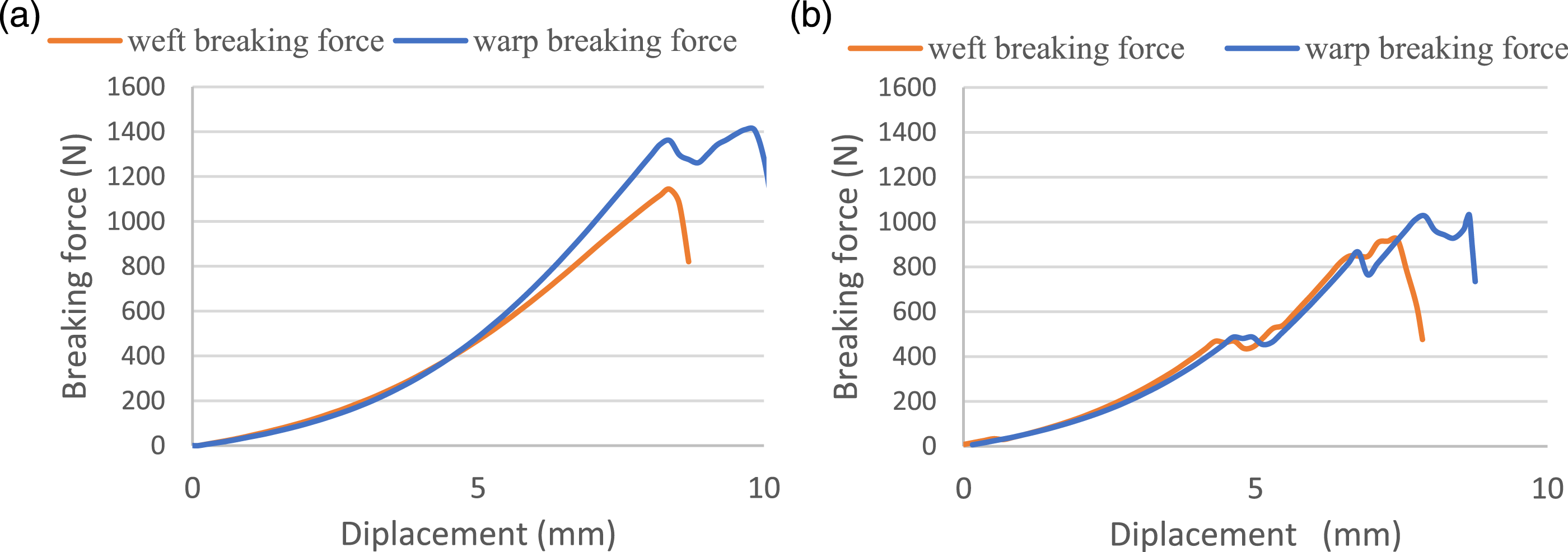
The strength and elongation of fabric ID 1 k in warp and weft directions were found to be higher than that of fabric ID 2 k, because of the difference in the structure and the properties of the used yarns and the fabric crimp.
Setup for measuring punching force of fabric and corresponding warp and weft tension
Figure 2-(a) shows the setup used for measuring the punching load and the tension on warp and weft yarns using a load transducer fixed on the gripping jaws on both sets of yarns. The fabric sample was fixed into a special attachment in such a way that the punching force caused biaxial stress during the puncher penetration. The initial pre-tension in both directions X and Y axis (Fx and Fy) can be adjusted; one of the jaws is fixed while the other is movable to allow for adjusting the pre-tension, as illustrated in Figure 1-(b).
23
The sample holder was placed on the lower jaw of the universal material testing machine as shown in Figure 2. The puncher, 5 mm diameter with a pointed tip (1 mm diameter), was grabbed by the upper jaw of the strength tester which moves downwards at a constant speed, pushing the puncher through the sample. The load-elongation curves of all tested fabrics were recorded and analysed. In the existing set-ups, used to study the punching performance of the fabrics, the value of the warp and weft yarns tension was recorded as a function of the time and continuously measured during the punching process. The weft and warp were pre-tensioned before the test by the movable jaw in both directions and adjusted at the start of the test. This clamping system could effectively eliminate the slippage of the tested samples during the punching by the puncher. Biaxial tension de-crimps warp and weft yarns, and when extended simultaneously, triggers the mechanical response of the fabric to the punching force. Five samples were tested to determine puncture resistance. Testing setup for measuring fabric punching force and tension on warp and weft yarns, (a) Measuring setup, (b) warp and weft initial tension setting device.
Fabric sample design for punching test
Woven fabrics were made from spun and multifilament Kevlar fibers. Their specifications and results of the different fabrics’ samples testing are given in Table 1. In this work, a new method was suggested to simulate a concept for the punching of fabric under biaxial stress. The sample, strained in the X-Y plane, was subjected to punching by a spike. During testing, the designed sample shape would allow to stress of the sample under the puncher in a square area leaving a sufficient area of fabric around the punched area to react with the punched area. The test sample geometry is shown in Figure 3; the sample is gripped on the X and Y-axis. Fabric sample dimensions.
Five samples were tested from each fabric, and the average values were reported. The main aim of using the designed fixture was to be able to run the biaxial extension on the fabric before applying the punching force under predetermined pre-tension (Fx and Fy) in X or Y direction, moreover, to simulate the effect of the surrounding fabric around the punched area which will deform and therefore, affect the punching mechanism. 23 The experimental design consisted of studying the effect of the following parameters on the fabric punching resistance: spinning technology, the number of layers, and punching speed.
Results and discussions
Analysis of the mechanism of punching Kevlar fabric
Mechanism of punching.

The possibilities of punching positions
The model of punching can be classified as passing between the filaments, Figure 4(a); Passing between warp and weft yarns, pushing weft or warp yarn aside, Figure 4(b); Punching at the warp or weft yarns body, Figure 4(c); or punching at the warp and weft at the crossing point, Figure 4(d). The number of yarns resisting the movement of the puncher depends on the area of the puncher tip and the number of ends and picks per cm, Figure 4(e). The value of the punching force will vary according to the position of the punching point relative to the fabric surface structure. The maximum value of punching resistance force is expected when the tip hits the fabric at the point of intersection of warp and weft yarns, Figure 4(d), and minimum when it passes freely between the spaces in the fabric surface, Figure 4(b). In some cases, especially in the multifilament yarn, the sharp tip of the puncher will pass through the wide yarn width, split it, and pass-through broking some filament, as shown in Figure 4(a). Punching possibilities.
From the above analysis, the punching resistance of the fabric will depend on the probability of the puncher’s position on the fabric surface; it means that puncture resistance is much smaller than unidirectional and biaxial fabric tensile strength.25,26
The probabilities of punching positions
Mode of failure by the puncher.

From the analysis of the above cases, it can be revealed that the weakest case occurs when the puncher passes through the space between warp and weft yarns (case 1), followed by case 6. While the maximum is when the puncher tip directly punches the fabric at a weft and warp intersection. This can be reached through the increase of the cover factor in both warp and weft.24,27 Thus, an increase in the number of threads per cm has a higher effect than the increase in yarn count. In case 5, the fabric punching resisting force depends on the structure of the weft and warp yarns and the possibility of the puncher tip passing through the yarn’s body, especially in the case of multifilament yarns, Kevlar (ID 2k). Figure 5 shows the forces acting on the warp and weft yarns at the tip of the puncher; the friction forces occur between warp, weft yarns, and metal of the tip. The slide of the yarns over the tip of the puncher will lead to changing the position of the warp and weft intersection on the tip. The fabric will change its position relative to the puncher tip, depending on the acting forces.11,28 Forces acting on warp and weft yarns at the intersection point.
The punching resistance force during puncher penetration in the direction of the puncher axis can be given as: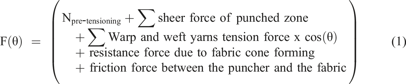
In the case the yarns slide over the puncher’s tip, they will be pushed with the tip over the yarn interlacement to the space between the yarns. In such a case, the fabric tightness plays a decisive role as well as the friction between the yarns and between the yarns and the puncher body.
18
Figure 6(a) shows the punching load-displacement curve, which shows that there are three distinguished zones. In the first zone, the puncher hits the fabric to form a cone followed by penetration of the puncher, zone II. The continuous punching through the fabric results in the diminishing in punching force till the complete penetration of the puncher, zone III. Figure 6(b) shows the analysis of the punching force-displacement curve and the photos of the fabric at the punching zone, which indicates various possibilities of the punched forms. Also, it indicates that both warp and weft yarns are broken. In the other cases, the puncher passes through the yarn’s broken filaments and leaves the others unbroken. In all incidents, the fabric under the punching is deformed; the cone shape is formed under the puncher tip. Mechanism of failure of fabric under punching. (a) Punching force-displacement curve (b) Various fabric failure under punching.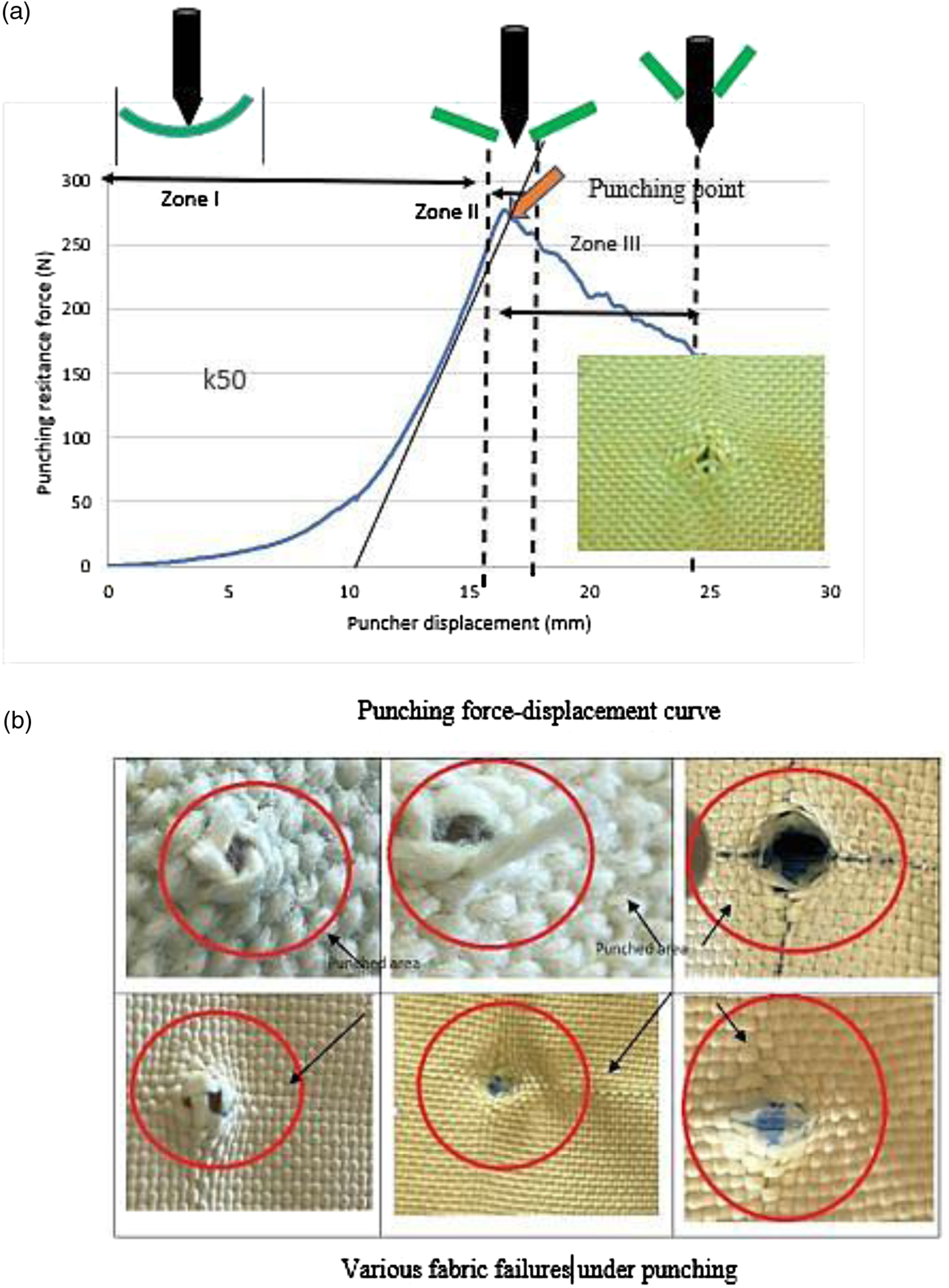
Effect of fabric orientation in multi-layer fabric laminate on punching force
To increase the punching resistance of the fabrics multi-layers of fabrics may be used. To reduce the probability of the puncher hitting on the space between the yarns, the minimum resistance to punching, more than one layer can be used. The number of open areas will be equal to the number of interlacements of the first layer = n1 per repeat and the number of spaces between the yarns = (n1)/2 per repeat. This will not change when two fabrics exactly lay on each other but if the upper fabric layer axis is rotated by θ = 45°, the number of interlacements of upper and lower fabric to be under each other will be n1 (large black circle), Figure 7, and there is an additional interlacement of the yarns in the upper layer (small black circle) = n1/2. This will reduce the area between the warp and weft yarns. The rotation of the upper fabric layer will reduce the probability of the puncher tip passing through the gap between the yarns. Effect of rotation of two layers of fabric on the free spaces between yarns.
In another situation when the number of warp and weft per cm is not equal, the fabric laminate rotation will change the probability of the interlacement presence in the punched area, depending on the value of warp and weft per cm and angle of rotation of one layer relative to the other. The effect of the angle depends on several factors including the specifications of the fabric and yarns.
Punching resistance of Kevlar fabric ID 2k
The Kevlar fabric ID 2k was tested on the setup, and the punching force value was recorded as well as the forces Punching resistance force of Kevlar fabric ID 2K, (a) Punching resistance force of Kevlar fabric ID 2k, single and double layer, (b) The ratio of (Fy + Fx)/punching force (η) during punching for sample ID 2k.
The ratio of the sum of tensions (Fy + Fx) to the punching force (η) is shown in Figure 8(b). The ratio (η) varied according to the characteristic of the punching mechanism; it will be equal to unity when both weft and warp yarns are broken under puncher action. At the start of the punching process η ≥ 1 and η ≤ 1 when the puncher tip passed through the punched hole. The resistance force only is due to friction between the puncher tip and the surrounding yarns during its movement.
To study the effect of fabric punching in the secondary area (greater than the cone punched area), samples of (100 × 10 mm) were tested. Figure 9 shows the punching resistance force in comparison to the normal sample size. It was revealed that not only the strength of the fabric in both warp and weft is important but also the presence of the fabric encircling the punched area has a role in determining the final value of the punching force. Punching resisting force – puncher displacement of fabric, Samples ID 2k and fabric stripe.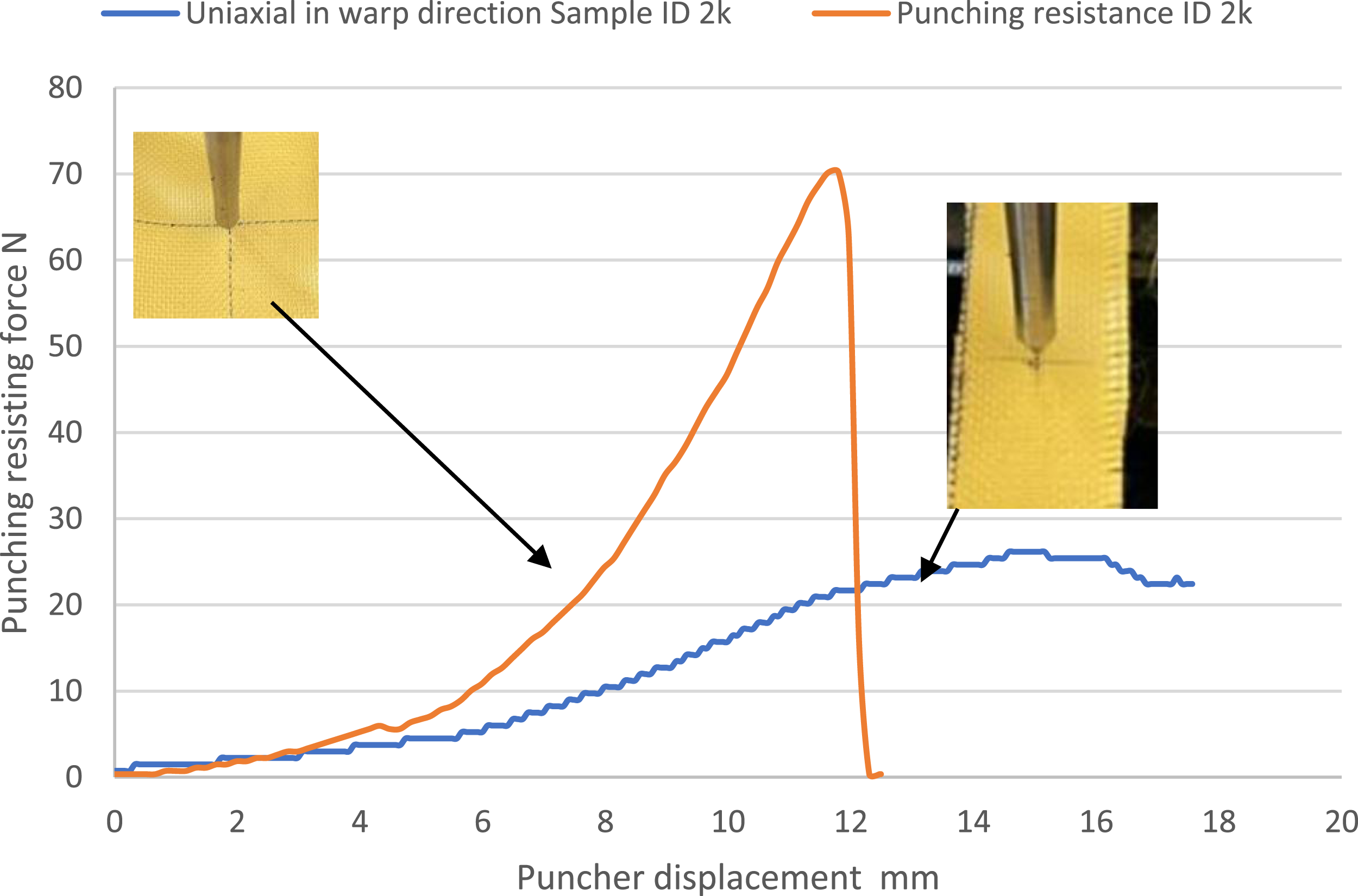
Comparing the two curves indicates that the effect of the presence of the fabric surrounding the punched area significantly increases the punching resistance force Fpunching and punching energy Epunching (Biaxial ID 2k one layers Fpunching = 70.19 N, Epunching = 255.75 mJ and for standard sample Fpunching = 26.160 N, Epunching = 231.89 mJ) the difference between the two values of energies represents the effect of deformation energy of the secondary area.
Enhancing the punching resistance of Kevlar Fabric
From the analysis of the punching model, the following main points can be concluded23,29: • Inter-fibers friction in the yarn increases the resistance to the puncher tip to strike the fabric and penetrate through the yarn body. • Higher inter-yarn friction results in less slippage of primary yarns at the punching point making more involvement of the surrounding yarns to the punched area. The sliding of primary yarns over each other is responsible for the structural stability in the punching point. Consequently, the stiffer fabric causes a higher shear modulus due to the inter-yarn friction in the punched area. • Higher inter-yarn friction can increase the frictional force between the warp and weft yarns at the points of intersection thus, the fabric will move in and bend under the punching force vertically towards the impact center more as the puncher moves down and consequently, bring more secondary yarns to share more stress. This action will result in additional punching resistance force since the punched fabric-formed cone will have more primary yarns.
Consequently, the use of the spun yarns can increase the secondary yarns that resist the puncher by keeping the integrity of the fabric under punching action due to high shear modulus. Fabric ID 1 k was suggested to replace the fabric ID 2 k for the sake of improving the fabric punching resistance based on the elevated fabric punching resistance in the secondary area. Samples of ID 1 k, (100 × 10 mm), were investigated. Figure 10 shows the punching resistance force of the fabric stripe in comparison to the normal sample. It was revealed that not only the strength of the fabric in both warp and weft is important but also the presence of the friction between the yarns encircling the punched area plays a role in determining the final value of the punching force. Both curves coincided with each other till the puncher penetration is completed for the fabric stripe. Punching resisting force – puncher displacement of fabric, Samples ID 1k and fabric stripe.
Punching resistance of Kevlar spun warp and weft yarn fabric
According to the above analysis, to enhance the punching resistance of Kevlar fabric, the fabric design requires to be of a high cover factor value, in addition, the yarns should have a high coefficient of friction to the puncher material. In this work, it was suggested to use fabric from coarse Kevlar spun yarns, sample ID 1 k. Samples of fabrics ID 1 k and ID 2 k have approximately the same cover factor, however, the fabric ID 1 k is woven from the weft and warp coarse Kevlar spun yarns, and sample ID 2 k from Kevlar continuous filament yarns, Table1. The punching force was measured as well as the forces Fx and Fy at different punching speeds.
Effect of punching velocity on punching resistance
Punching velocity is one of the critical parameters in the punching process. The punching velocity has a different effect depending on the tested material. The load–puncher displacement curve depends on the punching speed as shown in Figure 11. The punching speed will affect the fabric punching resistance since the puncher’s tip at touching the surface of the fabric causes strain propagation in all the fabric gripped areas. A compression, as well as a shear wave, will be created at the same instance. The compression stress will lead to the formation of the cone form under the puncher tip resulting in tension in warp and weft yarns. The formed cone will be resisted by the fabric bending stiffness as well as the shear stress in the zone with the unstrained yarns. The strain propagation in the tension yarns under the tip depends on the yarn specifications. Figure 11 shows the effect of the punching speed on the punching force. Effect of the punching velocity on the punching force.
The value of the ratio (η ≥ 1) was raised at a lower punching speed, Figure 12(a), the ratio (η) decreases tremendously, however, the resisting punching energy increases as shown in Table 4. Cone height was seen to reduce at high punching speed. (a) Ratio of resistance force of weft and warp yarns/punching force (η) during punching, (b) Total punching energy till the complete punching and that at the maximum value of punching force versus the punching speed. Effect of punching speed on the punching resistance forces and the punching energy (mm N) for fabric ID 1k. *Value of punching energy at up to maximum punching force. **Value of punching energy up to complete puncher.
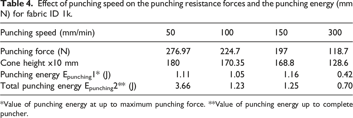
Table 4 gives the value of the effect of punching speed on the punching resistance forces and the punching energy (mm N) for fabric ID 2 k. The increase of the punching speed reduces the strain propagation speed in the yarns, consequently, reducing the area of the fabric resisting the punching force and the cone height was found to be less.
The difference between Epunching2 and Epunching1 decreases as the punching speed increases that is the complete punching is reached early. The effect of puncher speed on the warp and weft yarn tension during punching was found to be a function of the puncher displacement and the punching speed. The ratio of the sum of tensions (Fy + Fx) to the punching force (η) is shown in Figure 12(a). The ratio (η) varied according to the characteristic of the punching mechanism. It will be equal to η = 1 when both weft and warp yarns do not resist the puncher tip anymore, and it will be η ≤ 1 when the puncher passes through the fabric between the yarns to complete penetration. Figure 12(b) shows the effect of speed on Epunching2 and Epunching1. The value of Epunching2 is the total energy till the puncher completely passes through the fabric, while Epunching1 is the energy needed to punch the fabric. The difference between the two values of energies is to overcome the fabric stiffness and the frictional forces between the yarns and the puncher tip. This difference reduces as the punching speed increases. This is due to the fact that all the resisting forces, equation (1), reduce as the punching speed increases.
Figure 13 shows the effect of using two layers of fabric on changing the direction of the weft and warp by angle (α). In the case of using multiple layers of fabric, it was noticed that the angle (α) of rotation of warp yarns relative to each other in the successive laminate affects the value of the punching force Figure 13(a), as well as the ratio (η), as shown in Figure 13(b). The ratio of resistance force of weft and warp yarns/punching force versus puncher displacement, (a) punching resistance force for different values of angle (α), (b) Ratio (η) versus puncher displacement, b-Ratio of resistance force of weft and warp yarns/punching force (η) during punching.
Effect of rotation of two layers relative to each other on punching resistance force and energy.

Comparison between fabrics ID1k and ID 2k
The samples of fabrics ID 1k and ID 2 k have evaluated at the same punching speed of 100 mm/s and both punching force and the tensions Fx and Fy were recorded during the punching processes.
The punching resistance force of fabric ID1 k is higher than that of fabric ID 2 k as shown in Figure 14(b). This might be attributed to the higher shear modulus of the fabric ID 1 k than the other one ID 2 k. The total stress, according to von Mises, at a material point equals components of tensile stress and shear stress.
30
Consequently, the fabric having higher tensile properties and high shear modulus will have better punching resistance. (a) Photo of the fabric after punching, (b) Punching resistance force of fabrics ID1k and ID2k versus puncher displacement.
Comparison between Kevlar fabric ID 1k and ID 2k.

Analysis of the data which is given in Table 6 reveals that specific punching force was increased by 145% while the specific punching energy increased by 210% when using fabric ID 2 k. The use of two layers gives better performance.
Future studies on the multilayers of fabric ID 1 k investigate thermal protection, comfort, garment fit, and ergonomic mobility of the user, that fulfills the standard specifications by NIJ, 31 as well as the comfort properties for armour. 32
Conclusion
In this paper, Kevlar woven fabric, composed of spun yarns, as compared to the fabric, woven from continuous filament Kevlar yarns, for their punching resistance performance. Using spun yarns in fabric structure significantly increased the penetration force and energy of the fabric samples. With the use of spun yarns, the fabric structure can be kept much more balanced, and less slip of primary yarns occurs resulting in more punching resistance force. The effect of the punching speed shows that higher punching velocity results in less fabric punching resistance. The ratio of the resistance force of weft and warp yarns/punching force (η) during punching changes during puncher penetration and depends on the mechanical properties of the fabric and punching velocity. Based on the ANOVA analysis, the fabric type will have a significant effect on the specific punching force and energy. The measurements of fabrics ID 1 k and ID 2 k revealed that specific punching force increased by 145% while the specific punching energy increased by 210%.
Based on the obtained results, a better quasi-static punching penetration resistance performance of the fabric also can be obtained by using spun yarns. The current study opens a new research road for the application of Kevlar spun yarns in manufacturing punching resistance for industrial fabrics.
Footnotes
Declaration of conflicting interests
The author(s) declared no potential conflicts of interest with respect to the research, authorship, and/or publication of this article.
Funding
The author(s) received no financial support for the research, authorship, and/or publication of this article.