
Abstract
Light-weight fibers reinforced polymer (FRP) composite frames are essential parts of vehicles body in the aerospace and automotive industries. Composite frames are often designed in complex curved 3D geometry through the dry winding process. The winding process of homogeneously wound-up layers of fibers without overlapping and gaps is the main challenge in the fabrication of frames with consistent thickness and acceptable quality. In this study, an industrial robot and winding head are set with a novel optimum process to wind the dry fiber with the specified angles on the frame, to fabricate it with minimum overlapping and local commulation of fibers, yet without gaps. Mathematical models and algorithms are developed to determine the optimal number of simultaneously wounds rovings of fibers in a given layer. In addition, this study addresses the optimum dry winding of curved parts of frames that form a torus geometry. It is shown that the combination of layers of rovings wound successively on the frame at angles of 45°, 90° (i.e. the rovings are laid along with the frame), and −45°, is the most used variant of winding that provides the composite frame with higher strength. Results indicated that an optimal selection of the number and width of the rovings minimizes the overlap of the wound rovings, which saves up to 20% of the utilized fibers. The derived theory is verified on practical tests and experiments, which confirms the development of new suitable procedures to improve the fabrication of FRP composite frames.
Introduction
In the past decades, composite materials are increasingly replacing classic materials (such as wood, and metal) for their physical properties, energy-saving, and economic benefits.1–3 In general, composites are recognized with excellent mechanical properties, such as low weight, resistance to weathering, resistance to corrosion even in aggressive environments, long lifespan, etc.,3-5 A fiber-reinforced polymer (FRP) composite frame is a structure with a circular or rectangular cross-section that is made in close or open form, and that primarily is subjected to tensile, compressive, torsional, and bending loads.6,7 Fiber-reinforced polymer composite frames are used in the aerospace industry (e.g. as fuselage reinforcements, attaching windows to the fuselage, reinforcing the helicopter cabin),1,8,9 automotive applications (e.g. as car chassis, cab and door reinforcement), 8 and also in shipbuilding. Engineering, energy generation (e.g. as wind turbine blade reinforcement), agriculture;10,11 pipeline transportation (e.g. oil, liquids, and gas),1,12 and sports equipment, are other use of FRP composite frames. 6
The most commonly used production processes of FRP composite frames are braiding technology and filament winding. Braiding enables high adhesion of fibers to the frame surface, even in the case of a geometrically complicated frame shape,13,14 which enables the minimal risk of composite cracking during its loading. For special applications, it is possible to combine materials in partial directions (for example, carbon fibers/aramid fibers), or it is possible to exchange standard fibers to support synthetic yarn in one direction (unidirectional braiding).15–20 However, braiding technology is not applicable for the production of a composite closed frame with fiber reinforcement (technically difficult to implement).
The winding technology is used to manufacture frames with complex geometries, such as spherical and cylindrical vessels, tubes of various diameters, and a variety of convex and concave shapes.21–27 The main advantage of filament winding is the reinforcement content can be 60%–75%, to 80%, obtaining excellent mechanical characteristics. The second advantage is that the stiffness and strength of the composite are possibly enhanced in chosen directions by modifying the winding angle.
Some research has been done on the winding and optimization of composite frames. Duan et al. 28 proposed and verified a two-stage optimization scheme for the composite frame design. They performed tensile, bending, and torsional stiffness calculations of composite beams with a circular cross-section, that were expressed as explicit integral functions of the fiber winding angles. Numerical results showed that the proposed two-stage optimization eliminates the initial design dependence on fiber winding angle optimization; which helps to find a better design. A multistage design was developed by Yan et al. 29 and Duan et al., 30 which optimizes the winding angle, material, and laminate stiffness.
Similar issues are addressed in the book“Composite filament winding”23,31 where by combining the object geometry, roving parameters, strength, and feasibility to determine the optimal geometry for winding an object. Modeling of material properties depending on the physical-mechanical properties of the pressure vessel through the numerical simulation and derivation of the spiral winding angle was described by Zeng et al. 32 Guo et al. 33 developed a method for determining optimal beam winding trajectories. The method links structural design requirements with optimal structural properties including fiber orientation and volume reinforcement ratios. The resulting solution could be used directly to program the wrapping process. Similar problems have been addressed by Prado 34 and Bodea. 14
Some studies have focused on establishing the relationship between fiber arrangment, winding geometry, material, and mechanical properties of the composite. 35 Supian et al. 36 investigated the effect of the orientation of the hybrid winding of a composite tube on energy absorption and failure modes. Differences in response to dynamic loads for FRP with different types of reinforcement (metal, woven fabric, winding reinforcement) were studied by Gowid et al. 37 Li et al. 38 built a model to predict the local change in fiber angle due to forming at 220°C. They used tubes with thermoplastic winding (CF/PA6 combination) for the experiment, while they compared the prediction of the winding angles resulting from the forming process with the real winding angles obtained by an automated precision measurement system.
Many researches have been done on the dry winding of composite frame, while some also studied the optimization process, however such optimization lack in focusing on the fiber arrangement to minimize the overlapping and accommodation of fibers without gaps. Therefore, this motivates the authors of this work to investigate specifically a novel approach of optimization procedure that involved an industrial robot and winding head to purposely arrange the dry fiber on a frame structure without overlapping and gaps. The research is also extended to a degree of considering complex structures such as torus.
In this regard, the optimized winding process is described in the following section Material and winding optimization. The mathematical model of the winding is briefly described in Subsection Fiber winding, the geometrical representation of wound rovings by helixes is shown in Subsection General rules of winding optimization, and the determination of the optimal number of rovings used and their width is solved by Subsections Selection of the optimal number of fiber rovings and width of roving and Winding a curved part of the frame focuses on the problem of determining the optimal number of rovings and their width when wound in a curved part of the frame. The results of the practical tests and experiments are presented in Section (Results and discussion).
Material and winding optimization
This section focuses on the winding method and process. Winding heads and industrial robots are used during the winding of rovings on the non-bearing frame with a circular cross-section.39,40 The winding head contains three revolving rings with coils for fiber rovings (see Figure 2(a)). Rovings lead from the coils to the feeder-winding ring, which is a circle in the center of the winding head. A small ring diameter concentrates the rovings to one area, and rovings are placed/winded on the frame’s core. The winding head is fixed in the robot’s working space, while the non-bearing frame (that is usually made of polyurethane) is attached to the end of the working arm (end-effector) of the industrial robot (see Figure 2(b)). Based on the determined trajectory of the robot, the frame passes through the winding head; three fiber layers are created simultaneously. The trajectory of robot arm movement depends on the shape of the frame.
Figure 1 shows a schematic of the development of the composite frame. The content of the paper focuses on the highlighted portion of the diagram. Overview diagram of the composite frame development process.
Fiber winding
During the winding process, based on the right determined trajectory of the robot, the frame structure is gradually passed through the winding head. Three layers of fibers with different directions/angles (often 45°, 90°, – 45°) are placed on the surface of the frame (Figure 2(a)). A detailed procedure for calculating and determining the off-line trajectory of the robot is described in the literature.
8
Both frame types (open or closed) can be wound by rovings using this technique (see Figures 2 and 3(a)). Winding head with three coil rings and frame (a), and connection of frame to the robotic arm and robot cooperation with winding head during the winding process (b). Connection of closed frame to the robot-end-effector before starting the winding process (a), and example of the 3D shaped frame (b).

Performing the correct winding (i.e. correct winding angle and homogeneity of winding) of individual fiber layers is an essential prerequisite for producing composite with the required physical and mechanical properties.
41
Adherence to the correct winding of fibers rovings in each layer of reinforcement is conditioned by the perpendicular passage of the frame through the plane ρ of winding of the fibers (see Figure 4 - plane ρ1 of the fiber winding corresponding to coil ring k1 of the head when winding the first layer of fibers). At the same time, it is necessary that intersection points of frame axis o with plane ρ1 and axis s of winding head with plane ρ1 have the smallest possible distance (see Figure 4 - in this case, the points of intersections of the plane are identical – point M1). These conditions are described in detail in previous works by the same authors.1,9 Model of the winding process that shows the formation of the first fiber layer on the composite frame; the frame goes through a winding head (Figure 2(a)) represented by three coil rings, and three layers of fiber are created. The schema of the first fiber layer formation is shown in this figure.
To achieve the correct fiber angle in the winding of a given layer at a constant speed of frame passage through the winding head, it is necessary to determine the correct angular speed of rotation of the ring with coils. This issue is solved in detail in previous work. 1 The calculation of distance h of winding fibers on the frame from the coil ring at the required angle is also solved in detail in 1 (see Figure 4 – distance h1 of winding plane ρ1 from coil ring k1). At the same time, the article 1 deals with the winding of 3D frames, which consist of several parts with different radii.
In the case of a geometrically complicated shape of a frame (see Figure 3(b)), it is difficult to determine a suitable robot trajectory. Optimization of the robot trajectory for such cases using a differential evolution algorithm is described in detail in previous works.1,9
After winding the fibers, the frame is impregnated with resin and then thermally cured using, for example, (resin transfer molding) RTM technology. 42
General rules of winding optimization
The wound fiber roving can be represented by a helix formed on the surface of the frame. The roving has the shape of a rectangle in a cross-section. The height of the roving does not need to be considered for our purposes. The u-axis passes through the center of the roving (see Figure 5). The width of the roving is denoted by m, and the overlap of two consecutive wound rovings is denoted by δ. Then it applies to the distance d of two adjacent axes The winding part is represented by three rovings (red, blue, and green) in the plane. Axes u1, u2, and u3 pass through the centers of rovings 1, 2, and 3 of width m. The overlap of rovings δ is formed by winding two consecutive rovings.

The roving is wound on the frame; the u-axis of roving forms a helix on the frame envelope (see Figure 6(a) and (b)), detail can be found in.
43
Right-hand helix h
R
is formed on the surface of the frame at a positive angle of winding (denoted by +), with a negative angle of winding (denoted by –) is formed left-handed helix h
L
. One turn of right-handed helix h
R
(a), and left-handed helix h
L
(b). Characteristic triangle of the helix (c).
The following sections focus only on the winding in a positive direction and the creation of a right-handed helix. The following relations derived for a positive winding angle will be completely analogous even for the case of a negative winding angle. Figure 6(a), shows one turn of helix h
R
(the turn of roving). Helix h
R
is defined by axis o (axis of wrapped frame), radius r (radius of frame), and pitch v (height of one helix turn, measured parallel to axis o of helix). The value of v is equal to the distance of points A and B in Figure 6(a). A characteristic triangle defines helix angle α (see Figure 6(c), the length of the hypotenuse of the right triangle is equal to the length of helix h
R
in one turn, tg α =
Thus, the defined angle α is named the angle of winding of the roving. Angle β is defined as

In 3D Euclidean orthogonal coordinate system, the parametric equation of helix h
R
in the homogenous form can be expressed as (see 43)

The equation of the right-handed helix h
R
can also be expressed as the rotation of the point A1 = (r, 0, 0, 1)T around axis z (in our case o ≡ z, see Figure 6(a)), and its translation in a positive direction of axis z Initial points of right-handed helices. Two adjacent initial points are rotated by angle λ = π/2 (a), and λ = π/6 (b).


One turn (i.e. Graph of one turn of helices h1
R
and h2R.
Initial point A2 of helix h2 is rotated about the z-axis by angle λ with respect to the initial point A1 of the helix h1(see Figures 8 and 9). Attention will now turn to determine the distance of helices h1
R
and h2
R
. The unfolding of the cylindrical surface with one turn of the helices h1
R
and h2
R
into the plane is shown in Figure 9. The unfolding of the cylindrical surface with one turn of helices h1
R
and h2
R
into the plane.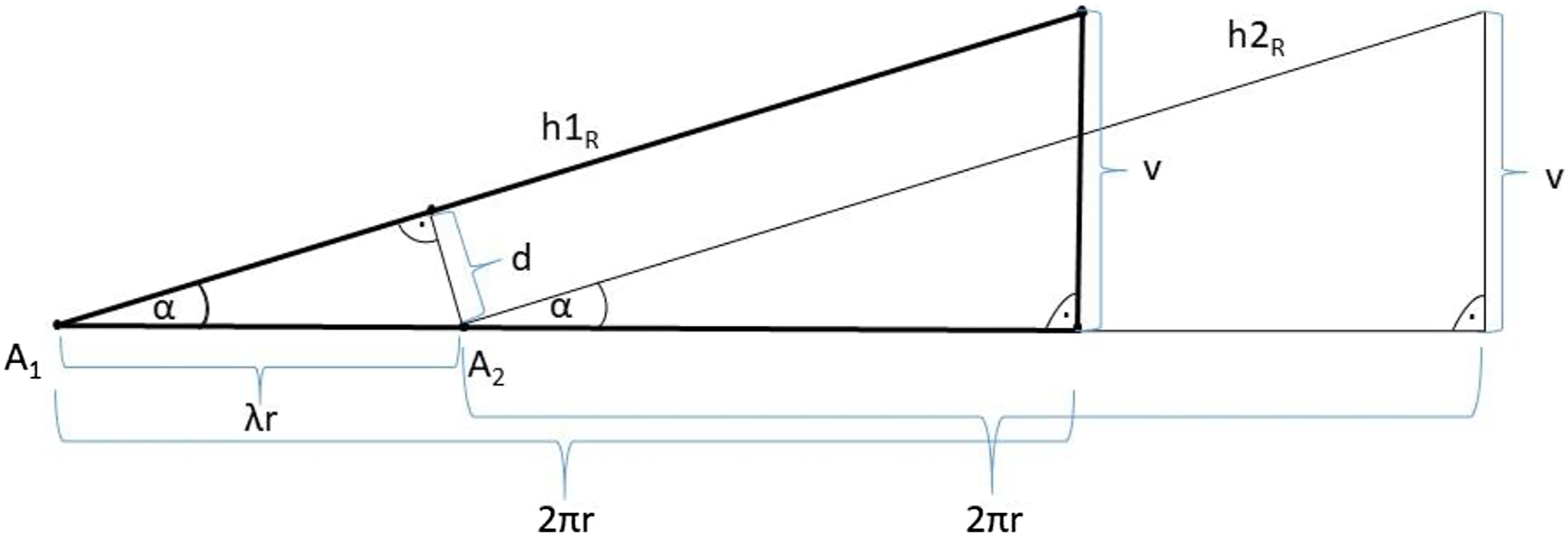
Figure 9 shows that the relationship

Relation (4) implies that the distance, d depends on the size λ of rotation, radius r of helices h1 R and h2 R , and the size of helix angle α. Function sin is increasing on interval (0, π/2). This means that with increasing angle α (required angle of winding of the fiber rovings), the distance d will also increase.
The winding of one roving at an angle (a) Fiber rovings on the surface of the frame at angles +
Selection of the optimal number of fiber rovings and width of roving
The ideal winding of rovings is such that the individual fiber layers are homogeneous. The wound rovings are placed side by side, follow each other smoothly, the entire surface of the frame is covered with fibers, and there is no overlap of adjacent rovings. This ideal winding is only possible with a straight frame. However, achieving this condition is difficult if the frame is geometrically more rugged (2D or 3D configuration). To achieve a qualified and acceptable composite frame winding process, it is essential to ensure the full coverage of the frame surface with minimal δ overlap of adjacent rovings, see Figure 5.
As mentioned in the introduction of this section, axes u1, and u2 of two adjacent fiber rovings (see Figure 5) create two adjacent helices h1 R and h2 R , during the winding process. The distance of these helices is given by relation (4). Equation (1) defines the relationship between the width m of the rovings and distance d of the two wound rovings.
Now the focus is on determining the optimal number n of wound rovings and the width m of roving. A straight frame with radius r and helix angle α (see Figure 6(a)) is considered. The number of used rovings increases with the frame radius r and helix angle α (winding angle). In general, narrower rovings are more appropriate than wider rovings to achieve a homogeneous winding of fibers onto the frame.
Following the relations (1) and (4), the width m of used fiber rovings is given by the relation

The size of frame radius r and the required α winding angle for the specified fiber layer is fixed. Equation (5) allows two basic procedures: 1. Determining the number n of rovings used in the winding process of one layer of fibers (i.e. the number of bobbins used on the coil ring) for the specified m width of roving. 2. Calculation of optimal roving width m for specified number n of rovings used during the winding process.
Determining the optimal number of rovings
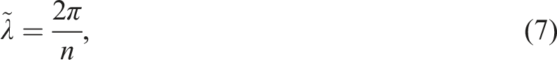
It is assumed that the width m of fiber roving, radius r of the frame, and winding angle α is specified. The optimal number n of rovings for winding the layer of fibers is calculated. The rotation angle λ between two adjacent windings (see Figures 7 and 8) of rovings is expressed from relation (5). Rotation angle

The entire surface of the frame is covered with wound rovings and at the same time, there are minimal overlaps of the rovings for the number n of rovings given by relation (6).
An actual angle of rotation between the two following rovings is denoted as

Values of optimal number n of used rovings, corresponding to the rotation angle
Calculation of optimal roving width
It is assumed that rotation angle λ between two adjacent rovings (and thus the number n of roving used), radius r of the frame, and winding angle α are entered. Then, the optimal width m of roving is calculated. Overlap δ is equal to zero in the case of optimal width m of roving. Then it implies from relation (5)

If the number of rovings n used for winding is known, then the angle λ of rotation for the neighboring two wound rovings is equal to the value

The optimal m width of fiber roving for a specified number n of rovings, frame radius r, and winding angle α can be calculated using relations (9) and (10).
Winding a curved part of the frame
Winding a curved part of a frame with a circular cross-section is the most challenging task of winding technology. In general, the frame could be a 3D curved structure. However, the curved part of the frame is very often shaped only in 2D and forms part of a torus (see Figure 2(b), Figure 11(a), detail is provided in the literature ).
43
Attention is given to a more detailed study of winding such a part of the frame. The torus is defined by its center S, radius R of the torus axis o, and radius r of a circular cross-section of the torus, as shown in Figure 11(b). Frame curvature often copies the shape of a torus (a). Floor plan of a torus - description of torus parameters (b).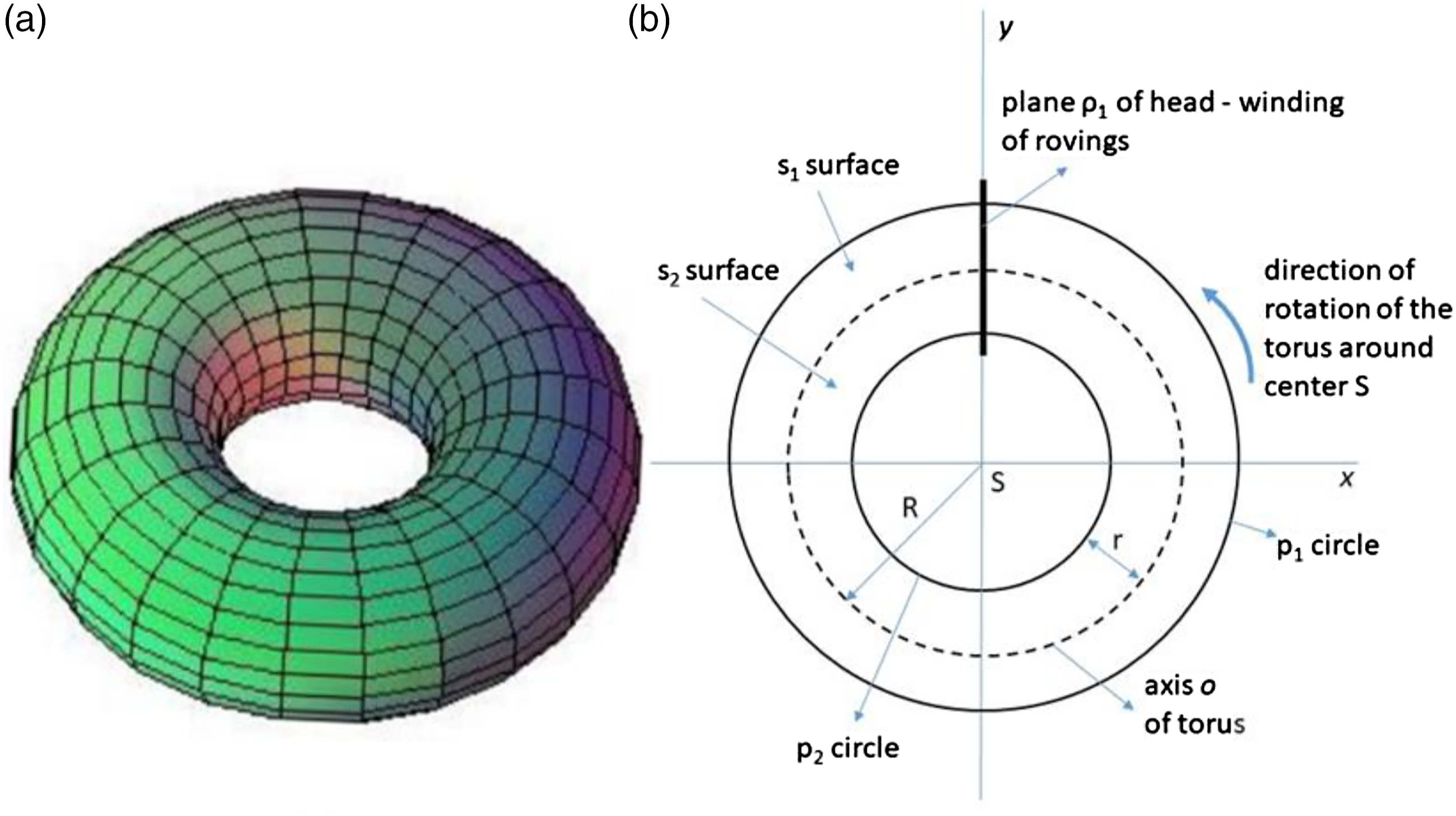
The outer part s1 of the torus surface is larger than the inner part s2 of the torus surface (see Figure 11(b)). This disproportion relates to the difficulty of making a homogeneous fiber layer. Figure 12 shows the winding of the roving on the surface of the torus at an angle of Roving on a torus at (a) an angle of 
Now, the attention is on the size of the circumference of circle p1 and circle p2 of the torus in Figure 11(b). Circle p1 creates the outer circumference and circle p2 inner circumference of the torus. Circumference size

Optimal number of rovings for winding of curved frame part
As it is stated in the introduction, curved parts of the frames most often form parts of tori. Therefore, we will solve the problem of winding the frame in the shape of a torus. As already mentioned in subsection fiber winding, it is necessary for right winding the frame passes perpendicularly to the winding plane of fiber rovings (see Figures 4 and 2(b), detail is described in the literature).1,8,9
It was assumed torus is connected to the robot-end-effector, rotates around its center S and goes through the winding head (and therefore through rotated coil ring k1 which forms the first layer of wound fibers, similar to Figure 4) and orthogonally goes through the winding plane ρ1 (i.e. its axis o orthogonal to ρ1, see Figure 11(b)). It is assumed a constant circumferential velocity of the torus. The circumferential speed of axis o is denoted as


It follows from relations (12), (13), and (14)

The required

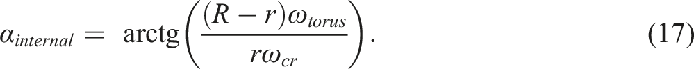
The outer circumference p1 (see Figure 11(b)) of the torus has a higher speed circumferential than internal circumference p2. It is seen from relations (16) and (17) that winding angle
The possibilities of using derived relationships to achieve optimized winding of rovings on the frame are shown in the following section.
Results and discussion
In this section, the derived mathematical relations and conclusions for specific input parameters and their application to practical examples are applied.
Calculation of optimal number of rovings
The specified optimal number n of rovings and the corresponding overlap

Based on the values given in each row of Table 1, the percentage p value of the area of the roving overlaps with respect to the total wound area can be calculated by a simple relation
Example – winding with the optimal number of rovings
In this practical example, the goal is to wind carbon rovings on a straight core (straight frame). The winding parameters are; radius of frame r = 16 (mm), roving winding angle
The longitudinal central axis of the roving forms a left-handed helix hL (see Figure 6(b)), pitch v (height of one helix turn, measured parallel to axis o of helix; see Figure 6(c)) is equal to Presentation of the winding of rovings to a straight core. One (a), three (b), five (c), and six (d) rovings are wound on the core according to helix parameters (The individual pictures present this procedure).
Calculation of optimal width of roving
The calculated optimal roving width m for specified winding input parameters.
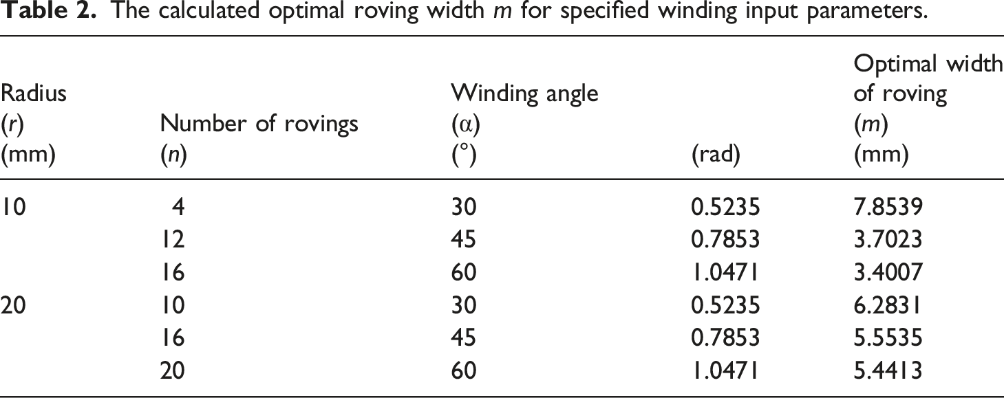
In practice, it is necessary to choose the smallest integer greater than width m or equal to m of the rovings supplied by the roving manufacturer at the specified number of rovings used (i.e. the number of used coils with rovings).
The derived mathematical models in Section Material and winding optimization, enable the determination of the number n of roving and their width m for winding a compact layer of fibers rovings.
Example – winding curved frame – part of the torus
Input values for winding rovings on a frame with torus geometry.

Note that the second radius r of the torus corresponds to the radius of the frame.
Firstly, 
Therefore, fiber rovings will be wound on the torus at angle α = π/4(rad) = 45° with respect to the axis o of the torus at
Rovings on the outer circumference of the torus (circle p1, see Figure 11(b)) will be wound at an angle given by relation (16)
At the same time, the rovings on the internal circumference of the torus (circle p2) will be wound at an angle given by the relation (17)
It could be seen that the rovings are wound at a greater angle on the outer circumference than on the inner circumference of the torus. As a result, there occurs often insufficient fiber rovings coverage of the surface on the outer circumference of the torus and overlapping of the fiber rovings on the inner circumference of the torus.
As already mentioned in the previous Section Material and winding optimization, the covering of the entire surface of the torus by rovings is an important condition for ensuring a sufficiently high-quality layer of reinforcing fibers rovings. The following, very important condition, is to minimize overlaps of the wound rovings.
Since eight rovings are used for winding (and thus also eight spools located on the circumference of the specified coil ring), two adjacent rovings on the frame are rotated by angle 
This distance d corresponds to winding angle α with respect to the o-axis of the torus. Distance 
Analogously, distance 
At width m of the roving equal to
The selection of roving in which the width
The following Figure 14 shows the winding of a torus-shaped frame successively with one, two, four, and six rovings at an angle of – 45°. In this case, the width of the roving Presentation of the winding of a torus-shaped frame successively with one (a), two (b), four (4), and six (d) with 9 mm wide rovings.
Winding angles on the outer and inner circumference of the torus
Values of winding angles on the outer and inner circumference of the torus and the distance between the central axes of two adjacent wound rovings depend on the entered winding angle α.

Table 4 clearly shows that as the α winding angle increases (relative to axis o of the torus, see Figure 11(b)), values of α
outer
, α
internal
, d, d
outer
and d
internal
increase. At the same time, it is true
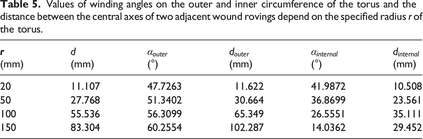
Winding angles on the circumference of the torus depending on the frame radius
Values of winding angles on the outer and inner circumference of the torus and the distance between the central axes of two adjacent wound rovings depend on the specified radius r of the torus.
Conclusion
This study focuses on the issue of achieving high-quality production of FRP composite frames. The winding process covers several layers of fiber rovings that are wound onto an open or closed non-load bearing frame. Ensuring the homogeneity and desired winding angle of each layer is a prerequisite for producing a quality composite frame. It is aimed to introduce the procedure to determine the optimal number of spools placed on a coil ring (i.e. the number of wound fiber rovings), and the width of the roving, which depend on the winding angle and radius of the frame. The number of rovings increases with the growth of the winding angle. It is shown that through the optimal determination of the number of rovings used along with rovings width, the possibility of material savings of up to 20% could be achieved. On the other hand, fiber winding optimization of curved frames, which often forms part of the torus, was developed and discussed. The optimized winding of rovings of such a curved frame is determined based on the geometric parameters of the torus. It is shown that, for a larger radius of the torus central-axis compared to the radius of the frame, a better-homogenized winding could be achieved. The winding parameters are chosen such that no gaps are created during winding on the outer circumference of the torus and at the same time roving overlaps are minimized on the inner circumference of the torus. A few experimental tests are also demonstrated in which the results of the test calculations are close to the experiment data.
In this study, the quality of winding is solved mainly from a geometric point of view. Ensuring the correct winding geometry is a necessary prerequisite for producing a quality fiber reinforcement for the composite frame. The procedures outlined in the article make it possible to determine the necessary parameters for the specific task of rovings winding onto the frame and thus avoid unsuitable set of parameters of the winding process.
Future research activities will focus on detailed testing of the physical performance of the composite frame under various static and fatigue loads. At the same time, the research will be extended to the generalization of the findings presented in this article to composite frames with a cross-section in the shape of an ellipse, triangle, rectangle, trapezoid, etc.
Footnotes
Declaration of Conflicting Interests
The author(s) declared no potential conflicts of interest with respect to the research, authorship, and/or publication of this article.
Funding
The author(s) disclosed receipt of the following financial support for the research, authorship, and/or publication of this article: This work was supported by the Ministry of Education, Youth, and Sports of the Czech Republic and the European Union (European Structural and Investment Funds Operational Program Research, Development, and Education) in the framework of the project “Modular platform for autonomous chassis of specialized electric vehicles for freight and equipment transportation”, Reg. No. CZ.02.1.01/0.0/0.0/16_025/0007293, as well as the financial support from internal grants in the Institute for Nanomaterials, Advanced Technologies and Innovations (CXI), Technical University of Liberec (TUL).